Language selection

Search

Patent 2639697 Summary

Third-party information liability

Some of the information on this Web page has been provided by external sources. The Government of Canada is not responsible for the accuracy, reliability or currency of the information supplied by external sources. Users wishing to rely upon this information should consult directly with the source of the information. Content provided by external sources is not subject to official languages, privacy and accessibility requirements.

Claims and Abstract availability

Any discrepancies in the text and image of the Claims and Abstract are due to differing posting times. Text of the Claims and Abstract are posted:

  • At the time the application is open to public inspection;
  • At the time of issue of the patent (grant).
(12) Patent: (11) CA 2639697
(54) English Title: SNOW MARKER FOR FIRE HYDRANTS AND OTHER UTILITIES
(54) French Title: MARQUEUR A NEIGE POUR PRISES D'EAU D'INCENDIE ET AUTRES SERVICES PUBLICS
Status: Deemed expired
Bibliographic Data
(51) International Patent Classification (IPC):
  • E01F 9/60 (2016.01)
  • E01F 9/50 (2016.01)
  • E03B 9/00 (2006.01)
(72) Inventors :
  • LOCKHART, EARL ROBERT (Canada)
(73) Owners :
  • LOCKHART, EARL ROBERT (Canada)
(71) Applicants :
  • LOCKHART, EARL ROBERT (Canada)
(74) Agent: OYEN WIGGS GREEN & MUTALA LLP
(74) Associate agent:
(45) Issued: 2013-03-05
(22) Filed Date: 2008-09-19
(41) Open to Public Inspection: 2010-03-18
Examination requested: 2010-09-17
Availability of licence: N/A
(25) Language of filing: English

Patent Cooperation Treaty (PCT): No

(30) Application Priority Data:
Application No. Country/Territory Date
12/233007 United States of America 2008-09-18

Abstracts

English Abstract

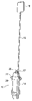
The invention provides marking apparatus for a fire hydrant or other utilities fixtures comprising a mast-holding bracket comprising a hollow pipe, means for removably securing the pipe to the fire hydrant or other utilities fixtures and an elongated mast removably received in the hollow pipe, the mast comprising a solid cylindrical flexible core and a flexible outer shell for mounting on the core, further comprising fastening means for securing the mast to the pipe. The apparatus can be attached to the outlet of a fire hydrant, the hole for the lifting bolt of a transformer or to a junction box, or as part of a concrete pedestal.


French Abstract

L'invention offre un appareil de marquage pour une borne-fontaine ou autres installations fixes de services publics comprenant un support de retenue de mât comportant un tuyau creux, un moyen pour fixer le tuyau de manière amovible à la borne-fontaine ou autres installations fixes de services publics et un mât allongé inséré de manière amovible dans le tuyau creux, le mât comprenant un noyau flexible cylindrique solide et une enveloppe externe souple pour la fixation au noyau, ainsi que des dispositifs de fixation pour fixer le mât au tuyau. L'appareil peut être fixé à la sortie d'une borne-fontaine, à l'orifice du boulon de soulèvement d'un transformateur ou d'une boîte de connexion ou il peut faire partie d'un socle en béton.

Claims

Note: Claims are shown in the official language in which they were submitted.


-9-
What is claimed is:

1. A marking apparatus for marking the location of a fire hydrant or other
utilities fixtures buried under a layer of snow on an outdoor surface,
comprising a mast-holding bracket comprising a hollow pipe, means for
removably securing said pipe to said fire hydrant or other utilities fixtures
and an elongated mast removably received in said hollow pipe, said mast
extending generally vertically upwardly from said fire hydrant or other
utilities fixture when so received in said hollow pipe and comprising a solid
cylindrical flexible core, indicator means secured adjacent the upper end of
said core for indicating said location and a flexible plastic cylindrical
outer
shell for slidably mounting coaxially on the core, further comprising
fastening means for securing said mast to said pipe; wherein said mast has a
length whereby said indicator means is located above said snow layer when
said mast is so received in said hollow pipe and wherein said fastening
means for securing said mast to said pipe comprises piercing means for
piercing through said plastic outer shell and into said core.

2. The marking apparatus according to claim 1 wherein said means for
removably securing said pipe to said fire hydrant or other utilities fixtures
comprises a plate secured to said pipe and having an aperture for attachment
to the outlet of a fire hydrant.

3. The marking apparatus according to claim 1 wherein said means for
removably securing said pipe to said fire hydrant or other utilities fixtures
comprises fastening means adapted for securement to a threaded hole in a
transformer box which receives a transformer lifting bolt.


-10-
4. The marking apparatus according to claim 1 wherein said means for
removably securing to said pipe to said fire hydrant or other utilities
fixture
comprises fastening means adapted for securement to a lifting bracket of a
transformer box.

5. The marking apparatus according to claim 1 wherein said mast-holding
bracket is secured to a concrete base.

6. A marking apparatus according to claim 1 wherein said solid core of said
elongated mast is made from a pultruded fiberglass.

7. A marking apparatus according to claim 6 wherein said flexible cylindrical
outer shell for mounting on the core is made from a coloured plastics
material.

8. A marking apparatus according to claim 1 wherein said indicator means
comprises a panel of reflective material attached to the upper end of said
elongated mast.

9. The marking apparatus according to claim 1 wherein said fastening means
for securing said mast to said pipe comprises a piercing bolt extending
through said pipe and plastic outer shell into said core.

10. The marking apparatus according to claim 1 wherein said hollow pipe is
provided adjacent a lower end thereof with flexible tying means for securing
to said hollow pipe and tying around said fire hydrant.

Description

Note: Descriptions are shown in the official language in which they were submitted.


CA 02639697 2008-09-19

SNOW MARKER FOR FIRE HYDRANTS AND OTHER UTILITIES
Technical Field
[0001] The invention relates to markers for marking the location of fire
hydrants, electrical utility or other utilities fixtures which may
become buried under a snow cover.

Background
[0002] In climates where there is significant snowfall, it is important to be
able to locate important utilities such as fire hydrants which
become buried in snow. Various devices are used to mark such
utilities with something which will be visible above the snow.
Examples of such devices are shown in United States patents no.
3,044,435; 4,478,169; and 4,908,249. These may involve an
elongated mast, flag or pole which is secured to the hydrant flange.
Due to the attachment to the hydrant flange, the mast, flag or pole
must be pivotable or bendable so it can be moved out of the way to
attach a hose to the hydrant. Some devices have the mast mounted
on a fixed bracket which pivots and others are spring mounted,
which reduces the durability of the device and adds cost. Further
such devices are not readily adaptable to other types of utilities
such as junction boxes and transformers.

[0003] The foregoing examples of the related art and limitations related
thereto are intended to be illustrative and not exclusive. Other
limitations of the related art will become apparent to those of skill
in the art upon a reading of the specification and a study of the
drawings.

3 0 Summary
[0004] The following embodiments and aspects thereof are described and
illustrated in conjunction with systems, tools and methods which


CA 02639697 2008-09-19

-2-
are meant to be exemplary and illustrative, not limiting in scope. In
various embodiments, one or more of the above-described problems
have been reduced or eliminated, while other embodiments are
directed to other improvements.
[0005] The invention provides a marking apparatus for a fire hydrant or
other utilities fixtures comprising a mast-holding bracket
comprising a hollow pipe, means for removably securing the pipe
to the fire hydrant or other utilities fixtures and an elongated mast
removably received in the hollow pipe, the mast comprising a solid
cylindrical flexible core and a flexible outer shell for mounting on
the core, further comprising fastening means for securing the mast
to the pipe. The apparatus can be attached to the outlet of a fire
hydrant, the hole for the lifting bolt or bracket of a transformer or to
a junction box, or as part of a concrete pedestal.

[0006] In addition to the exemplary aspects and embodiments described
above, further aspects and embodiments will become apparent by
reference to the drawings and by study of the following detailed
descriptions.

Brief Description of Drawings
[0007] Exemplary embodiments are illustrated in referenced figures of the
drawings. It is intended that the embodiments and figures disclosed
herein are to be considered illustrative rather than restrictive.

[0008] Fig. I is a perspective view of the invention attached to a fire
hydrant.


CA 02639697 2008-09-19

-3-
[0009] Fig. 2A is a detail elevation of the piercing bolt for the holder
bracket assembly.

[00010] Fig. 2B is a top view of the holder bracket assembly shown in Fig.
2C.

[00011] Fig. 2C is a detail elevation, broken away of the holder bracket
assembly.

[00012] Fig. 3 is a detail perspective view of the invention attached to a
fire
hydrant.

[00013] Fig. 4 is a perspective view of a variation of the holder bracket
assembly invention for attachment to a transformer box for a Low
Profile Transformer (LPT) or a Pad Mounted Transformer (PMT).

[00014] Fig. 5A is a detail elevation of the piercing bolt for the holder
bracket assembly shown in Fig. 4.

[00015] Fig. 5B is a top view of the holder bracket assembly shown in Fig.
4.

[00016] Fig. 5C is an elevation view of the variation of the holder bracket
shown in Fig. 4.
[00017] Fig. 6A is a detail elevation of the piercing bolt for the holder
bracket assembly shown in Fig. 6C.

[00018] Fig. 6B is a top view of the holder bracket assembly shown in Fig.
6C.


CA 02639697 2008-09-19

-4-
[00019] Fig. 6C is an elevation view of a further variation of the holder
bracket assembly invention for attachment to a transformer box for
a Pad Mounted Transformer (PMT).
[00020] Fig. 6D is a detail elevation of the flat bar for the holder bracket
assembly shown in Fig. 6C.

[00021] Fig. 7 is a perspective view of the variation of the holder bracket
shown in Fig. 6C installed on a transformer box.

[00022] Fig. 8 is a detail elevation of the piercing bolt for the holder
bracket
assembly shown in Fig. 9B.

[00023] Fig. 9A is a top view of a variation of a junction box holder bracket
assembly invention for attachment to a concrete plinth.

[00024] Fig. 9B is a cross-sectional view of the variation of the junction box
holder bracket assembly invention taken along lines 9-9 of Fig. 9A.
[00025] Fig. 1 OA is a detail elevation, broken away of the exterior shell for
the mast assembly.

[00026] Fig. IOB is a detail elevation, broken away of the pultrusion rod for
the mast assembly.

[00027] Fig. IOC is a detail elevation, broken away of the mast assembly.


CA 02639697 2008-09-19

-5-
Description
[00028] Throughout the following description specific details are set forth
in order to provide a more thorough understanding to persons
skilled in the art. However, well known elements may not have
been shown or described in detail to avoid unnecessarily obscuring
the disclosure. Accordingly, the description and drawings are to be
regarded in an illustrative, rather than a restrictive, sense.

[00029] With reference to Fig. 1 to 3, a fire hydrant 10 is provided with a
snow marker 12, comprising a mast-holding bracket 14, mast 16
and sign 18. Fire hydrant 10 typically has a nut 20 for opening and
closing the valve and a cap 22 which has screw threads for
attaching to threaded outlet 24 for attaching the fire hose. Mast-
holding bracket 14 (Fig. 2) comprises a hollow cylindrical steel
pipe or tube 26 to which is welded a rectangular steel plate 28
having an aperture 30 sized to fit over outlet 24. Pipe 26 has a hole
32 extending completely through it adjacent its lower end, for
receiving a nylon strap 34. Pipe 26 also has a hole 40 extending
completely through it for receiving a pin 42 which is inserted into
hole 40 and both ends of pin 42 are welded to pipe 26 to provide a
lower stop for mast 16. Pipe 26 also has a threaded hole 36 in one
side for receiving a threaded piercing bolt 3 8 extending completely
through it adjacent its lower end.

[00030] The construction of mast 16 is shown in further detail in Fig. IOA-
C. It comprises a solid fiberglass pultrusion rod 44 as the core of
the mast and a hollow brightly colored exterior shell 46 which
surrounds rod 44. Rod 44 is flexible and returns to its original
shape when bent or pushed over. The use of a solid fiberglass
pultrusion has the advantage that should the rod be vandalized to


CA 02639697 2008-09-19

-6-
the point of breaking, it will splinter into soft fibers and so will not
cause injury if a person comes into contact with it. Preferably the
mast is about 16 feet in length, and may be formed as shown in Fig.
IOC from two 8-foot long fiberglass rods joined by a coupling tube
50 and bolts 48 which fasten the coupling tube through drilled holes
in rods 44. Sign 18 may be an aluminum sheet which is bolted to
the rod 44 with a reflective decal adhered to both sides. The
exterior shell 46 may be a plastic with bright yellow and red stripes.
Shell 46 slides over the fiberglass rod 44 and is secured by piercing
bolt 38 when installed in pipe 26.

[00031] To install the device on hydrant 10, cap 22 is removed from outlet
24 and it is insured that there is sufficient exposure of the hydrant
10 between the ground and the outlet to receive the mast-holding
bracket 14. Aperture 30 of the mast-holding bracket 14 is then
placed over outlet 24 and the cap 22 replaced and tightly screwed
into place while ensuring the mast-holding bracket 14 is vertical.
Where the bottom of the fire hydrant is exposed above the soil,
nylon strap 34 is extended through hole 32 in the mast-holding
bracket 14 and extended around the fire hydrant and tightened
snugly to maintain the mast-holding bracket 14 in position. Sign 18
is then bolted to the top of rod 44 and tube 46 slid over rod 44 until
it is stopped by sign 18. A tie strap (not shown) can be installed
through holes near the top of tube 46 to prevent the spiral marker
from separating. The lower end of the combined rod 44, tube 46
and sign 18 assembly is then lowered into the mast-holding bracket
14 and piercing bolt 38 tightened until it pierces into rod 44.

[00032] Fig. 4 and 5A-C illustrate a variation of the holder bracket
assembly 54 for attachment to a transformer box 68. Mast-holding


CA 02639697 2008-09-19

-7-
bracket 54 in this case comprises a hollow cylindrical steel pipe or
tube 56 to which is welded a hex head bolt 55 and having a stop
plate 57 welded to the bottom of the pipe. Bolt 55 is screwed into
the threaded hole 60 in the transformer box which receives the
transformer lifting bolt. A pal nut 62 and two nuts 64 and lock
washers 66 (Fig. 4) are threaded onto the end of bolt 55 prior to
threading it into the threaded hole 60 in the transformer box. The
mast-holding bracket 54 is rotated until tight, then backed off to the
vertical position before tightening nuts 62, 64. The mast 16 is then
installed as above.

[00033] Fig. 6A-D and 7 illustrate a variation of the holder bracket
assembly 74 for attachment to a transformer box 70. Mast-holding
bracket 74 in this case comprises a hollow cylindrical steel pipe or
tube 76 to which is welded a U- bolt 75 and having a stop plate 87
welded to the bottom of the pipe. U-bolt 75 is fastened to a
transformer lifting bracket 77 by means of a hex jam nut 72, flat bar
71, flat washer 78 and hex nut 79. The mast-holding bracket 74 is
tightened in the vertical position. The mast 16 is then installed as
above and piercing bolt 73 in inserted.

[00034] Fig. 8 and 9A-B illustrate a variation of the holder bracket
assembly 84 for attachment to a pre-cast concrete pedestal 80 to
form a ground vault. Pre-cast concrete pedestal 80 is formed as a
concrete pyramid with a central hollow cylindrical chamber 81 for
receiving a steel pipe 83. Mast-holding bracket 84 in this case
comprises a hollow cylindrical steel pipe or tube 86, welded closed
at the lower end, which is fastened to pipe 83 by a bolt 85. Bolt 85
is screwed through holes in pipes 83 and 86. The mast 16 is then
installed as above and secured by tightening piercing bolt 88.


CA 02639697 2012-07-12

-8-
[00035] While a number of exemplary aspects and embodiments have been
discussed above, those of skill in the art will recognize certain
modifications, permutations additions and sub-combinations thereof.

Representative Drawing
A single figure which represents the drawing illustrating the invention.
Administrative Status

For a clearer understanding of the status of the application/patent presented on this page, the site Disclaimer , as well as the definitions for Patent , Administrative Status , Maintenance Fee  and Payment History  should be consulted.

Administrative Status

Title Date
Forecasted Issue Date 2013-03-05
(22) Filed 2008-09-19
(41) Open to Public Inspection 2010-03-18
Examination Requested 2010-09-17
(45) Issued 2013-03-05
Deemed Expired 2018-09-19

Abandonment History

There is no abandonment history.

Payment History

Fee Type Anniversary Year Due Date Amount Paid Paid Date
Application Fee $200.00 2008-09-19
Maintenance Fee - Application - New Act 2 2010-09-20 $50.00 2010-05-26
Request for Examination $400.00 2010-09-17
Maintenance Fee - Application - New Act 3 2011-09-19 $50.00 2011-06-27
Maintenance Fee - Application - New Act 4 2012-09-19 $50.00 2012-05-29
Final Fee $150.00 2012-12-18
Maintenance Fee - Patent - New Act 5 2013-09-19 $100.00 2013-06-26
Maintenance Fee - Patent - New Act 6 2014-09-19 $100.00 2014-05-06
Maintenance Fee - Patent - New Act 7 2015-09-21 $100.00 2015-06-03
Maintenance Fee - Patent - New Act 8 2016-09-19 $100.00 2016-08-15
Owners on Record

Note: Records showing the ownership history in alphabetical order.

Current Owners on Record
LOCKHART, EARL ROBERT
Past Owners on Record
None
Past Owners that do not appear in the "Owners on Record" listing will appear in other documentation within the application.
Documents

To view selected files, please enter reCAPTCHA code :


To view images, click a link in the Document Description column. To download the documents, select one or more checkboxes in the first column and then click the "Download Selected in PDF format (Zip Archive)" or the "Download Selected as Single PDF" button.

List of published and non-published patent-specific documents on the CPD .

If you have any difficulty accessing content, you can call the Client Service Centre at 1-866-997-1936 or send them an e-mail at CIPO Client Service Centre.


Document
Description 
Date
(yyyy-mm-dd) 
Number of pages   Size of Image (KB) 
Cover Page 2010-03-08 1 32
Abstract 2008-09-19 1 19
Description 2008-09-19 8 301
Claims 2008-09-19 2 50
Drawings 2008-09-19 9 72
Representative Drawing 2010-02-19 1 2
Claims 2012-07-12 2 76
Description 2012-07-12 8 294
Representative Drawing 2013-02-11 1 3
Cover Page 2013-02-11 1 32
Prosecution-Amendment 2010-09-17 1 36
Assignment 2008-09-19 4 130
Correspondence 2012-12-18 1 55
Prosecution-Amendment 2012-03-14 2 68
Prosecution-Amendment 2012-07-12 7 239