Language selection

Search

Patent 2640539 Summary

Third-party information liability

Some of the information on this Web page has been provided by external sources. The Government of Canada is not responsible for the accuracy, reliability or currency of the information supplied by external sources. Users wishing to rely upon this information should consult directly with the source of the information. Content provided by external sources is not subject to official languages, privacy and accessibility requirements.

Claims and Abstract availability

Any discrepancies in the text and image of the Claims and Abstract are due to differing posting times. Text of the Claims and Abstract are posted:

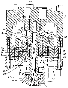
  • At the time the application is open to public inspection;
  • At the time of issue of the patent (grant).
(12) Patent Application: (11) CA 2640539
(54) English Title: ROTOR ATTACHMENT FOR COMPRESSOR
(54) French Title: ACCESSOIRE DE ROTOR POUR COMPRESSEUR
Status: Deemed Abandoned and Beyond the Period of Reinstatement - Pending Response to Notice of Disregarded Communication
Bibliographic Data
(51) International Patent Classification (IPC):
  • F04C 23/00 (2006.01)
  • F04C 18/02 (2006.01)
  • F04C 29/00 (2006.01)
(72) Inventors :
  • HALLER, DAVID K. (United States of America)
(73) Owners :
  • TECUMSEH PRODUCTS COMPANY
(71) Applicants :
  • TECUMSEH PRODUCTS COMPANY (United States of America)
(74) Agent: SMART & BIGGAR LP
(74) Associate agent:
(45) Issued:
(22) Filed Date: 2008-10-07
(41) Open to Public Inspection: 2009-04-09
Examination requested: 2008-10-07
Availability of licence: N/A
Dedicated to the Public: N/A
(25) Language of filing: English

Patent Cooperation Treaty (PCT): No

(30) Application Priority Data:
Application No. Country/Territory Date
60/978,680 (United States of America) 2007-10-09

Abstracts

English Abstract


A compressor having drive assembly including a crankshaft and a motor having a
stator and a rotor. The rotor is received on a crankshaft and secured to the
crankshaft via a
counterweight. In one exemplary embodiment, the counterweight is shrink-fit or
press-fit in
position on the crankshaft and the rotor is attached to the counterweight. In
one exemplary
embodiment, the rotor may be secured to the counterweight by fasteners, such
as bolts. The
interference between the counterweight and the crankshaft is sufficiently
strong to transfer
driving loads from the rotor and through the counterweight to drive the
crankshaft. In one
exemplary embodiment, the rotor includes a central opening having a diameter
larger than the
diameter of the crankshaft. This allows for the rotor to fit closely to the
crankshaft without
touching the same. As a result, the rotor may be easily assembled as a slip-
fit on the
crankshafts and then secured to the counterweights.


Claims

Note: Claims are shown in the official language in which they were submitted.

WHAT IS CLAIMED IS:
1. A drive assembly in a compressor, the drive assembly comprising:
a motor having a stator and a rotor;
a crankshaft connected to a compression mechanism; and
a counterweight secured to said crankshaft, said counterweight rotatably fixed
to said rotor, wherein said rotor is rotatably secured to said crankshaft
solely by said
counterweight.
2. The drive assembly of Claim 1, wherein said counterweight is secured to
said
crankshaft by one of a shrink-fit and a press-fit.
3. The drive assembly of Claim 2 wherein said rotor is secured to said
counterweight by means of at least one fastener.
4. The drive assembly of Claim 3 wherein said fastener is a bolt.
5. The drive assembly of Claim 1 wherein said rotor is secured to said
counterweight by means of at least one fastener.
6. The drive assembly of Claim 5 wherein said rotor is secured to said
counterweight by means of at least one fastener.
4

Description

Note: Descriptions are shown in the official language in which they were submitted.


CA 02640539 2008-10-07
ROTOR ATTACHMENT FOR COMPRESSOR
BACKGROUND
I. Field of the Invention.
100011 The present invention relates to compressors and, particularly, to
compressors
having a rotatable counterweight.
2. Description of the Related Art.
[00021 Compressors generally have a drive assembly including a motor having a
stator and
a rotor, in which the rotor is press-fit or shrink-fit to a crankshaft to
rotate the crankshaft and
drive a compression mechanism. Due to eccentric loading that occurs during the
rotation of
the compression mechanism, counterweights are attached to the rotor to
facilitate even weight
distribution during operation of the compressor. However, some rotors have
magnets
contained therein that may become demagnetized if they are heated to
facilitate a shrink fit.
Alternatively, the magnets andlor rotor may become damaged if the rotor is
forced on the
crankshaft to facilitate a press-fit. Additionally, when utilizing rotors
containing magnets, the
necessary manipulation of the rotor and extra assembly operations may be
difficult.
[0003] What is needed is an improvement over the foregoing.
SUMMARY OF THE INVENTION
[0004) The present invention provides a compressor having drive assembly
including a
crankshaft and a motor having a stator and a rotor. The rotor is received on a
crankshaft and
secured to the crankshaft via a counterweight. In one exemplary embodiment,
the
counterweight is shrink-fit or press-fit in position on the crankshaft and the
rotor is attached
to the counterweight. In one exemplary embodiment, the rotor may be secured to
the
counterweight by fasteners, such as bolts. The interference between the
counterweight and
the crankshaft is sufficiently strong to transfer driving loads from the rotor
and through the
counterweight to drive the crankshaft. In one exemplary embodiment, the rotor
includes a
central opening having a diameter larger than the diameter of the crankshaft.
This allows for
the rotor to fit closely to the crankshaft without touching the same. As a
result, the rotor may
be easily assembled as a slip-fit on the crankshaft and then secured to the
counterweight.
[0005] Advantageously, by limiting the need to shrink-fit or press-fit the
rotor to the
crankshaft, any potential distortion of the rotor is substantially eliminated.
For example, if
the rotor includes magnets, such as rare earth magnets, demagnetization of the
magnets in the
1
_ _ ,

~ . . ... .:. ... , . . . _ . , ,,,. , ,. ., .<. . . ,,.. ... . ... , .. _ . .
. .. .. .. .. ...
CA 02640539 2008-10-07
rotor is substantially prevented. Additionally, the rotor may be purchased
magnetized,
eliminating additional manufacturing costs and decreasing the difficulty in
assembling the
rotor to the crankshaft. Further, in order to press-fit the rotor to the
crankshaft, a relief is
commonly formed in the crankshaft to allow the rotor to be press-fit over a
small distance.
By eliminating the need to press-fit the rotor to the crankshaft, the need to
machine a relief
into the crankshaft is eliminated and the corresponding manufacturing time and
cost
decreased.
BRIEF DESCRIPTION OF THE DRAWINGS
[0006] The above-mentioned and other features and advantages of this
invention, and the
manner of attaining them, will become more apparent and the invention itself
will be better
understood by reference to the following description of an embodiment of the
invention taken
in conjunction with the accompanying drawing, wherein:
[0007] Fig. 1 is a cross-sectional view of the drive assembly of the present
invention.
[00081 Corresponding reference characters indicate corresponding parts. The
exemplification set out herein illustrates one preferred embodiment of the
invention, in one
form, and such exemplification is not to be construed as limiting the scope of
the invention in
any manner.
DETAILED DESCRIPTION
[0009] Referring to Fig. 1, crankcase 2, bearing support 5, bearing assembly 6
and drive
assembly 8 are shown in accordance with one exemplary embodiment of the
present
invention. Drive assembly 8 includes motor 10 having stator 12 and rotor 14.
Rotor 14 is
rotationally locked to crankshaft 16 via upper counterweight 18. Counterweight
18 has
opening 20 configured for receipt of crankshaft 16. In order to secure
counterweight 18 to
crankshaft 16, counterweight 18 is shrink-fit or press-fit to crankshaft 16 or
fixedly connected
by a suitable fastener. Once counterweight 18 is sufficiently secured to
crankshaft 16, rotor
14 is connected to counterweight 18.
[0010] In one exemplary embodiment, counterweight 18 and rotor 14 have
corresponding
apertures 22, 24, respectively, configured for the receipt of fasteners, such
as bolts 26. Bolts
26 include an oversized head 28 and a threaded portion 30 configured for
receipt of nut 32
thereon. By aligning apertures 22, 24 of counterweight 18 and rotor 14, bolt
26 may be
inserted therethrough and nut 32 secured to threaded portion 30 of bolt 26. In
order to
facilitate the assembly of rotor 14 to crankshaft 16, rotor 14 may have an
oversized aperture
extending therethrough. The oversized aperture of rotor 14 allows for rotor 14
to slip-fit on
2

_ .... .._. ;.
CA 02640539 2008-10-07
crankshaft 16. In this embodiment, rotor 14 does not tightly contact
crankshaft 16, but may
allow for a small gap to be formed therebetween.
100111 Additionally, lower counterweight 34 may also be secured through
counterweight
18 to crankshaft 16. Specifically, lower counterweight 34 further includes
aperture 36
configured for the receipt of bolt 26. By aligning aperture 36 with apertures
22, 24 in
crankshaft 16 and rotor 14, bolt 26 may be inserted through apertures 22, 24,
36 and nut 32
secured to threaded portion 30 of bolt 26. Once connected via bolt 26, lower
counterweight
34 and rotor 14 are rotationally secured to crankshaft 16 via counterweight
18. Thus, during
operation of the compressor, rotor 14 of motor 10 is rotated and the rotation
of rotor 14 is
transferred via contact region 36 of counterweight 18 to crankshaft 16.
Crankshaft 16 may
then correspondingly rotate a compression mechanism, such as a scroll
compression
mechanism (not shown).
[0012) The fluid is then discharged at a relatively high discharge pressure
through
discharge port 32. The compressor may further include other features such as
those described
in U.S. Patent No. 7,094,043 to Sldnner, issued August 22, 2006, and U.S.
Patent
No. 7,063,523 to Skinner, issued June 20, 2006, the entire disclosures of
which are expressly
incorporated by reference herein.
[0013] While this invention has been described as having a preferred design,
the present
invention can be further modified within the spirit and scope of this
disclosure. This
application is therefore intended to cover any variations, uses, or
adaptations of the invention
using its general principles. Further, this application is intended to cover
such departures
from the present disclosure as come within known or customary practice in the
art to which
this invention pertains and which fall within the limits of the appended
claims.
3

Representative Drawing
A single figure which represents the drawing illustrating the invention.
Administrative Status

2024-08-01:As part of the Next Generation Patents (NGP) transition, the Canadian Patents Database (CPD) now contains a more detailed Event History, which replicates the Event Log of our new back-office solution.

Please note that "Inactive:" events refers to events no longer in use in our new back-office solution.

For a clearer understanding of the status of the application/patent presented on this page, the site Disclaimer , as well as the definitions for Patent , Event History , Maintenance Fee  and Payment History  should be consulted.

Event History

Description Date
Time Limit for Reversal Expired 2012-10-09
Application Not Reinstated by Deadline 2012-10-09
Deemed Abandoned - Conditions for Grant Determined Not Compliant 2011-12-23
Deemed Abandoned - Failure to Respond to Maintenance Fee Notice 2011-10-07
Notice of Allowance is Issued 2011-06-23
Letter Sent 2011-06-23
Notice of Allowance is Issued 2011-06-23
Inactive: Approved for allowance (AFA) 2011-06-07
Amendment Received - Voluntary Amendment 2011-02-02
Inactive: S.30(2) Rules - Examiner requisition 2010-08-09
Amendment Received - Voluntary Amendment 2009-08-10
Amendment Received - Voluntary Amendment 2009-04-23
Application Published (Open to Public Inspection) 2009-04-09
Inactive: Cover page published 2009-04-08
Inactive: IPC assigned 2009-03-30
Inactive: First IPC assigned 2009-03-30
Inactive: IPC assigned 2009-03-30
Filing Requirements Determined Compliant 2008-11-05
Inactive: Filing certificate - RFE (English) 2008-11-05
Letter Sent 2008-11-04
Application Received - Regular National 2008-11-04
Request for Examination Requirements Determined Compliant 2008-10-07
All Requirements for Examination Determined Compliant 2008-10-07

Abandonment History

Abandonment Date Reason Reinstatement Date
2011-12-23
2011-10-07

Maintenance Fee

The last payment was received on 2010-08-20

Note : If the full payment has not been received on or before the date indicated, a further fee may be required which may be one of the following

  • the reinstatement fee;
  • the late payment fee; or
  • additional fee to reverse deemed expiry.

Please refer to the CIPO Patent Fees web page to see all current fee amounts.

Fee History

Fee Type Anniversary Year Due Date Paid Date
Application fee - standard 2008-10-07
Request for examination - standard 2008-10-07
MF (application, 2nd anniv.) - standard 02 2010-10-07 2010-08-20
Owners on Record

Note: Records showing the ownership history in alphabetical order.

Current Owners on Record
TECUMSEH PRODUCTS COMPANY
Past Owners on Record
DAVID K. HALLER
Past Owners that do not appear in the "Owners on Record" listing will appear in other documentation within the application.
Documents

To view selected files, please enter reCAPTCHA code :


To view images, click a link in the Document Description column. To download the documents, select one or more checkboxes in the first column and then click the "Download Selected in PDF format (Zip Archive)" or the "Download Selected as Single PDF" button.

List of published and non-published patent-specific documents on the CPD .

If you have any difficulty accessing content, you can call the Client Service Centre at 1-866-997-1936 or send them an e-mail at CIPO Client Service Centre.


Document
Description 
Date
(yyyy-mm-dd) 
Number of pages   Size of Image (KB) 
Abstract 2008-10-07 1 23
Description 2008-10-07 3 157
Claims 2008-10-07 1 22
Drawings 2008-10-07 1 54
Representative drawing 2009-03-13 1 24
Cover Page 2009-04-02 2 65
Description 2011-02-02 3 156
Claims 2011-02-02 1 22
Acknowledgement of Request for Examination 2008-11-04 1 190
Filing Certificate (English) 2008-11-05 1 167
Reminder of maintenance fee due 2010-06-08 1 116
Commissioner's Notice - Application Found Allowable 2011-06-23 1 165
Courtesy - Abandonment Letter (Maintenance Fee) 2011-12-02 1 173
Courtesy - Abandonment Letter (NOA) 2012-03-19 1 164
Fees 2010-08-20 1 36