Language selection

Search

Patent 2640721 Summary

Third-party information liability

Some of the information on this Web page has been provided by external sources. The Government of Canada is not responsible for the accuracy, reliability or currency of the information supplied by external sources. Users wishing to rely upon this information should consult directly with the source of the information. Content provided by external sources is not subject to official languages, privacy and accessibility requirements.

Claims and Abstract availability

Any discrepancies in the text and image of the Claims and Abstract are due to differing posting times. Text of the Claims and Abstract are posted:

  • At the time the application is open to public inspection;
  • At the time of issue of the patent (grant).
(12) Patent Application: (11) CA 2640721
(54) English Title: WALL ELEMENT
(54) French Title: ELEMENT DE MUR
Status: Deemed Abandoned and Beyond the Period of Reinstatement - Pending Response to Notice of Disregarded Communication
Bibliographic Data
(51) International Patent Classification (IPC):
  • E04C 2/34 (2006.01)
  • B32B 3/28 (2006.01)
  • E04C 2/36 (2006.01)
(72) Inventors :
  • SNEL, WILHELMUS JAN REINIER KAREL
(73) Owners :
  • UNDA MARIS HOLDING N.V.
(71) Applicants :
  • UNDA MARIS HOLDING N.V. (Netherlands Antilles)
(74) Agent: GOWLING WLG (CANADA) LLP
(74) Associate agent:
(45) Issued:
(86) PCT Filing Date: 2007-01-16
(87) Open to Public Inspection: 2007-08-02
Availability of licence: N/A
Dedicated to the Public: N/A
(25) Language of filing: English

Patent Cooperation Treaty (PCT): Yes
(86) PCT Filing Number: PCT/NL2007/050019
(87) International Publication Number: WO 2007086737
(85) National Entry: 2008-07-29

(30) Application Priority Data:
Application No. Country/Territory Date
2000001 (Netherlands (Kingdom of the)) 2006-01-30

Abstracts

English Abstract


A wall element comprising two outer layers extending at least substantially
parallel to each other, between which at least two intermediate layers are
provided, wherein each intermediate layer extends between the outer layers in
a zigzag fashion, each intermediate layer comprising first parts that extend
at least substantially parallel to the outer layers and second parts that
extend between adjacent first parts, wherein first parts of one intermediate
layer that face towards one outer layer are connected to said one outer layer,
and wherein first parts of the other intermediate layer that face towards the
other outer layer are connected to said other outer layer, a characteristic
feature being the fact that said intermediate layers are identical in shape,
with the intermediate layers being connected along their adjoining second
parts.


French Abstract

L'invention concerne un élément de mur comportant deux couches extérieures s'étendant au moins de manière sensiblement parallèle l'une par rapport à l'autre, entre lesquelles au moins deux couches intermédiaires sont mises en AEuvre, chaque couche intermédiaire s'étendant entre les couches extérieures en zigzag, chaque couche intermédiaire comportant des premières parties qui s'étendent au moins de manière sensiblement parallèle par rapport aux couches extérieures et des deuxièmes parties qui s'étendent entre les premières parties adjacentes, les premières parties d'une couche intermédiaire qui font face vers une couche extérieure étant raccordées à ladite une couche extérieure, et les premières parties de l'autre couche intermédiaire qui font face vers l'autre couche extérieure étant raccordées à ladite autre couche extérieure, une caractéristique étant le fait que lesdites couches intermédiaires sont identiques en forme, les couches intermédiaires étant raccordées le long de leurs deuxièmes parties contiguës.

Claims

Note: Claims are shown in the official language in which they were submitted.

1
CLAIMS
1. A wall element (1) comprising two outer layers (2,3)
extending at least substantially parallel to each other,
between which at least two intermediate layers (4,5) are
provided, wherein each intermediate layer extends between
the outer layers (2,3) in a zigzag fashion, each
intermediate layer comprising first parts (6) that extend
at least substantially parallel to the outer layers (2,3)
and second parts (7) that extend between adjacent first
parts (6), wherein first parts (6) of one intermediate
layer (4) that face towards one outer layer (2) are
connected to said one outer layer (2), and wherein first
parts (6) of the other intermediate layer (5) that face
towards the other outer layer (3) are connected to said
other outer layer (3), characterised in that said
intermediate layers (4,5) are identical in shape, with
the intermediate layers (4,5) being connected along their
adjoining second parts (7), the facing first parts (6) of
the adjoining intermediate layers (4,5) thereby defining
a space between them.
2. A wall element (1) according to claim 1, wherein the
intermediate layers (4,5) are glued together along their
adjoining second parts (7).

2
3. A wall element (1) according to claim 1 or 2, wherein the
first and the second parts (6,7) of each intermediate
layer at least substantially flat.
4. A wall element (1) according to claim 1, 2 or 3, wherein
each intermediate layer is at least substantially made of
a material selected from the group consisting of
corrugated cardboard, solid cardboard and wood.
5. A wall element (1) according to any one of the preceding
claims 1-4, wherein each outer layer is at least
substantially made of a material selected from the group
consisting of corrugated cardboard, solid cardboard and
wood.
6. A wall element (1) according to any one of the preceding
claims 1-5, wherein the wall element (1) is arranged for
accommodating pipes, cables and the like and/or
insulation material and/or stiffening material in the
intermediate layers (4,5) thereof.
7. A method for manufacturing a wall element (1) according
to any one of the preceding claims 1-6, which method
comprises the following steps to be carried out in
succession:
- first folding strips of a starting material into
zigzag shapes along fold lines, each zigzag shape
comprising first parts (6) extending at least
substantially parallel to outer layers (2,3) yet to
be provided, and second parts (7) extending between
adjacent first parts (6);

3
- then joining the two zigzag shapes, which are
identical in shape, together along their adjoining
second parts (7), the facing first parts (6 ) of the
twa adjoining zigzag shapes thereby defining a space
between them; and
- subsequently affixing the outer layers (2,3) to the
joined-together zigzag shapes on either side thereof.
8. A method according to claim 7, wherein said zigzag shapes
(4,5) are glued together.
9. A method according to claim 7 or 8, wherein the fold
lines (8) are in the form of score lines.

Description

Note: Descriptions are shown in the official language in which they were submitted.


CA 02640721 2008-07-29
WO 2007/086737 PCT/NL2007/050019
WALL ELEMENT
The invention relates to a wall element comprising two outer
layers extending at least substantially parallel to each
other, between which at least two intermediate layers are
provided, wherein each intermediate layer extends between the
outer layers in a zigzag fashion, each intermediate layer
comprising first parts that extend at least substantially
parallel to the outer layers and second parts that extend
between adjacent first parts, wherein first parts of one
intermediate layer that face towards one outer layer are
connected to said one outer layer, and wherein first parts of
the other intermediate layer facing towards the other outer
layer are connected to said other outer layer.
Such a wall element is described in the continuation-in-part
of US patent application No. 10/617,430 dd 11 July 2003 of
the present Applicant. To form said wall element, two wall
element halves (see figures 13 thereof) are first made,
wherein each half consists of one outer layer and one zigzag-
shaped intermediate layer connected thereto and wherein first
parts of the intermediate layer that face towards the outer
layer being connected to said outer layer. Then the two
halves are joined together (see figure 14 thereof).
The object of the invention is to improve the wall element
that is known from the aforesaid continuation-in-part of US
patent application No. 10/617,430, in the sense that a wall
element exhibiting an optimum constructional stiffness is
provided for use as a structural element of a building, as a
wall panel, for example in a partition wall, etc., while
leaving out the time-consuming and labour-intensive step of

CA 02640721 2008-07-29
WO 2007/086737 PCT/NL2007/050019
2
first joining two wall element halves together. Incidentally
it is noted that the term "wall element" is understood to
include an element for a wall, a floor, a ceiling, a roof,
etc.
In order to accomplish that objective, a wall element of the
kind referred to in the introduction is according to the
invention characterized in that said intermediate layers are
identical in shape, with the intermediate layers being
connected along their adjoining second parts. Research has
shown that the present zigzag shape, in which the
intermediate layers are connected along their adjoining
second parts, results in an unexpectedly great constructional
stiffness of the wall element, so that the wall element can
be exposed to large forces without its shape stability being
affected. The invention makes it possible to join the
intermediate layers together first into an independent
semifinished product and subsequently provide the outer
layers to form the final wall element. In principle the
present wall element may be made of any material, for example
aluminium, but it is in particular made of a cellulose
material.
The intermediate layers are preferably nested, fitting
together like plastic coffee cups, as it were. Typically, the
facing first parts of the adjoining intermediate layers
define a space between them, which means that they are spaced
apart.
In a preferred embodiment of a wall element according to the
invention, the intermediate layers are glued together along
their adjoining second parts. Said glueing in particular

CA 02640721 2008-07-29
WO 2007/086737 PCT/NL2007/050019
3
takes place along glue lines that have been applied to said
adjoining second parts beforehand.
In another preferred embodiment of a wall element according
to the invention, the first and the second parts of each
intermediate layer at least substantially flat. As a result,
an optimum bonding surface is created, which additionally
enhances the structural integrity of the wall element.
In another preferred embodiment of a wall element according
to the invention, each intermediate layer is at least
substantially made of a material selected from the group
consisting of corrugated cardboard, solid cardboard and wood.
Preferably, each outer layers is likewise at least
substantially made of a material selected from the group of
corrugated cardboard, solid cardboard and wood. The
intermediate layers and/or the outer layers are in particular
made of corrugated cardboard whose corrugations extend in a
zigzag fashion along the surface thereof, so that deformation
of the intermediate layers and/or the outer layers in random
directions along the surface will hardly be possible, if at
all. In another preferred variant, each intermediate layer is
at least substantially made of a material selected from the
group consisting of metal and plastic. If a metal is
selected, said metal will in particular be aluminium or
steel. Preferably, the outer layers are likewise made of a
metal, such as aluminium or steel.
It is preferable to form the intermediate layers from layers
of paper/cardboard, each layer at least substantially being
built up of a corrugated sublayer and a flat sublayer affixed
to one side thereof, with the paper/cardboard layers being
interconnected by means of an adhesive, in particular a glue,

CA 02640721 2008-07-29
WO 2007/086737 PCT/NL2007/050019
4
which is present on the ridges of the corrugated sublayers.
In a special embodiment, said intermediate layers may also be
made up of a corrugated sublayer, which is provided with a
flat sublayer on either side thereof, with the two flat
sublayers and the corrugated sublayer present therebetween
being interconnected by means of an adhesive, in particular a
glue present on the ridges of said corrugated sublayer. In a
preferred variant, the outer layers are likewise formed from
layers of paper/cardboard, each layer comprising a corrugated
sublayer and a flat sublayer present on one side thereof,
wherein the bond between the paper/cardboard layers is
effected by means of an adhesive that is present on the
ridges of the corrugated sublayers. In another preferred
variant, the outer layers are made of wood. In yet another
preferred variant, the outer layers are each made up of a
gypsum board, which is built up of two paper/cardboard
external layers, between which an internal gypsum layer is
present. Said gypsum board may be connected to the
intermediate layer of the present wall element either
directly or with the interposition of a paper/cardboard
layer.
It is noted that the term paper is generally used to indicate
lighter sorts of paper, whilst the term cardboard is
frequently used for heavier grades of paper. Within the
framework of the invention, no restriction as regards the
sort of material is intended when using the terms paper or
cardboard and weight.
In another preferred embodiment of a wall element according
to the invention, the wall element is arranged for
accommodating pipes, cables and the like and/or insulation
material and/or stiffening material in the intermediate

CA 02640721 2008-07-29
WO 2007/086737 PCT/NL2007/050019
layers thereof. The present wall element in itself provides
an ideal thermal insulation on account of the relatively
large air cavities that are present in the zigzag-shaped
intermediate layer, but said cavities may also be used
5 partially or entirely for drawing pipes, cables and tubes
therethrough or for placing insulation and/or stiffening
material therein.
The invention also relates to a method for manufacturing a
wall element according to the invention, which method
comprises the following steps to be carried out in
succession:
- first folding strips of a starting material into zigzag
shapes along fold lines, each zigzag shape comprising
first parts extending at least substantially parallel to
outer layers yet to be provided, and second parts
extending between adjacent first parts;
- then joining the two zigzag shapes, which are identical
in shape, together along their adjoining second parts;
and
- subsequently affixing the outer layers to the joined-
together zigzag shapes on either side thereof.
In this way the joined-together intermediate layers are first
formed as semifinished products and subsequently provided
with the outer layers on either side thereof.
In a preferred embodiment of a wall element according to the
invention, the zigzag shapes are glued together.

CA 02640721 2008-07-29
WO 2007/086737 PCT/NL2007/050019
6
In another preferred embodiment of a wall element according
to the invention, the folds lines are in the form of score
lines.
The invention will now be explained in more detail with
reference to figures illustrated in a drawing, in which:
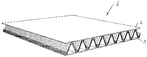
- Figure 1 is a schematic, perspective view of a preferred
variant of a wall element according to the invention; and
- Figure 2 is a schematic, longitudinal sectional view of
the wall element of figure 1.
Figure 1 shows a wall element (1) entirely made of corrugated
cardboard, which consists of two mutually parallel outer
layers (2,3) and three intermediate layers (4,5,9), which
extend in a zigzag fashion between said outer layers (2,3)
As figure 2 shows, each intermediate layer (4,5,9) comprises
first parts (6) extending parallel to the outer layers (2,3),
as well as second parts (7) extending obliquely between
adjacent first parts (6) . As far as the outer intermediate
layers (4,5) are concerned, first parts (6) of the
intermediate layer (4) that face towards the outer layer (2)
are glued to said outer layer (2), whilst first parts (6) of
the intermediate layer (5) that face towards the outer layer
(3) are locally glued to said outer layer (3) . All the
intermediate layers (4,5,9) are identical in shape, being
nested, as is illustrated in figures 1 and 2. All the
intermediate layers (4,5,9) are fitted together in the
illustrated manner, like plastic coffee cups, as it were,
with the intermediate layers (4,5,9) being glued together
along their adjoining second parts (7) . Glue lines have to
that end been applied to the adjoining parts (7).

CA 02640721 2008-07-29
WO 2007/086737 PCT/NL2007/050019
7
As already noted before, each zigzag-shaped intermediate
layer (4,5,9) is formed from a strip of starting material
consisting of corrugated cardboard, which strip is folded
into the zigzag shape along fold lines (8) in the form of
score lines. The outer layers (2,3) are flat layers made of
corrugated cardboard.
It is noted that the invention is not limited to the
embodiment as shown herein, but that it also extends to other
variants that fall within the scope of the appended claims.

Representative Drawing
A single figure which represents the drawing illustrating the invention.
Administrative Status

2024-08-01:As part of the Next Generation Patents (NGP) transition, the Canadian Patents Database (CPD) now contains a more detailed Event History, which replicates the Event Log of our new back-office solution.

Please note that "Inactive:" events refers to events no longer in use in our new back-office solution.

For a clearer understanding of the status of the application/patent presented on this page, the site Disclaimer , as well as the definitions for Patent , Event History , Maintenance Fee  and Payment History  should be consulted.

Event History

Description Date
Application Not Reinstated by Deadline 2012-01-16
Time Limit for Reversal Expired 2012-01-16
Deemed Abandoned - Failure to Respond to Maintenance Fee Notice 2011-01-17
Letter Sent 2009-07-16
Inactive: Single transfer 2009-06-02
Inactive: Correspondence - Transfer 2009-06-02
Inactive: Cover page published 2008-11-20
Inactive: Declaration of entitlement/transfer - PCT 2008-11-17
Inactive: Notice - National entry - No RFE 2008-11-17
Inactive: First IPC assigned 2008-11-06
Application Received - PCT 2008-11-05
National Entry Requirements Determined Compliant 2008-07-29
Application Published (Open to Public Inspection) 2007-08-02

Abandonment History

Abandonment Date Reason Reinstatement Date
2011-01-17

Maintenance Fee

The last payment was received on 2009-12-22

Note : If the full payment has not been received on or before the date indicated, a further fee may be required which may be one of the following

  • the reinstatement fee;
  • the late payment fee; or
  • additional fee to reverse deemed expiry.

Please refer to the CIPO Patent Fees web page to see all current fee amounts.

Fee History

Fee Type Anniversary Year Due Date Paid Date
Basic national fee - standard 2008-07-29
MF (application, 2nd anniv.) - standard 02 2009-01-16 2008-12-19
Registration of a document 2009-06-02
MF (application, 3rd anniv.) - standard 03 2010-01-18 2009-12-22
Owners on Record

Note: Records showing the ownership history in alphabetical order.

Current Owners on Record
UNDA MARIS HOLDING N.V.
Past Owners on Record
WILHELMUS JAN REINIER KAREL SNEL
Past Owners that do not appear in the "Owners on Record" listing will appear in other documentation within the application.
Documents

To view selected files, please enter reCAPTCHA code :


To view images, click a link in the Document Description column. To download the documents, select one or more checkboxes in the first column and then click the "Download Selected in PDF format (Zip Archive)" or the "Download Selected as Single PDF" button.

List of published and non-published patent-specific documents on the CPD .

If you have any difficulty accessing content, you can call the Client Service Centre at 1-866-997-1936 or send them an e-mail at CIPO Client Service Centre.


Document
Description 
Date
(yyyy-mm-dd) 
Number of pages   Size of Image (KB) 
Description 2008-07-29 7 253
Claims 2008-07-29 3 92
Abstract 2008-07-29 1 69
Drawings 2008-07-29 1 36
Representative drawing 2008-11-18 1 16
Cover Page 2008-11-20 1 51
Reminder of maintenance fee due 2008-11-17 1 115
Notice of National Entry 2008-11-17 1 208
Courtesy - Certificate of registration (related document(s)) 2009-07-16 1 102
Courtesy - Abandonment Letter (Maintenance Fee) 2011-03-14 1 174
Reminder - Request for Examination 2011-09-19 1 117
PCT 2008-07-29 6 176
PCT 2008-07-30 4 168
Correspondence 2008-11-17 1 24
Fees 2008-12-19 1 40
Fees 2009-12-22 1 39