Note: Descriptions are shown in the official language in which they were submitted.
CA 02641107 2013-12-02
RAILROAD SNOW REMOVAL SYSTEM
Technical Field
This invention relates to railroad snow removal systems. More particularly,
the
present invention relates to a monitoring and control system for a network of
snow removal
devices.
Background of the Invention
During the winter it is not uncommon for snow and ice to accumulate on and
around
railroad tracks. To maintain optimal track performance it is desirable to keep
certain areas of
the track free of snow and ice year round. For example, it is particularly
desirable to keep the
areas where tracks cross each other (frogs) and where tracks merge or split
(switches) free of
snow and ice. Though the system of the present disclosure will be described
herein primarily
with reference to railroad track switches, the description is not meant to be
limiting. It should
be appreciated that the system is applicable to other applications as well.
Railroad track switches are used to divert a train from one train track to
another train
track. The railroad switches typically include a pair of rails that move from
a first position to a
second position. The switches typically include moving parts that are exposed
to the
environment. Snow and ice build-up on the switch can cause the switch to
malfunction.
A number of different types of railroad track switch snow removers are known.
See,
for example, U.S. Patent No. 5,824,997 to Reichle et al.; U.S. Patent No.
4,391,425 to Keep,
Jr.; and U.S. Patent No. 4,081,161 to Upright. The railroad track switch snow
remover often
includes a blower that blows heated air or ambient air across the switch.
Though some
heaters and blowers of the snow removing devices are electric powered, most
are gas
powered, as they are typically located in remote locations. Sometimes the snow
removers
include temperature and moisture sensors so that an operator at a remote
location can
determine when to turn the devices on or off. Some devices are programmed to
automatically turn themselves on or off depending on the reading from the
sensors.
1
CA 02641107 2013-12-02
A problem with the existing systems is that malfunctioning device can be
difficult to
identify. In some cases, the devices are turned on when it is not snowing or
turned off when it
is snowing. In the first case, fuel is wasted, and in the second, the switch
may malfunction due
to undesirable snow accumulation in the tracks. Moreover, existing switch snow
removal
control systems are not configured to collect, store and/or report data
regarding performance
and other conditions of the device. A system that can be used to effectively
monitor and
control snow removal devices located in remote locations is desirable.
Summary of the Invention
The present invention relates to a system for controlling and monitoring snow
removal
devices. According to one aspect of the invention, there is provided a
railroad snow removal
network comprising:
a plurality of snow removal devices positioned at geographic locations each
including a
snow removal element, a sensor for detecting snow fall, a transmitter and a
processor,
wherein each snow removal device is configured to automatically turn on when
snow fall is
detected;
a computing device including a processor, a transmitter and a receiver, the
computing
device configured to acquire weather data from a weather reporting source
wherein the data
corresponds to the geographic locations of the snow removal devices, wherein
the computing
device is configured to send an alert when a snow removal device is turned off
when the
weather reporting source indicates that snow is falling at the corresponding
location; and
a user interface configured to display at least the location of the snow
removal device.
In one embodiment, the measured data is compared with the queried data. If the
measured data is within a certain predetermined acceptable range compared to
the queried
weather data, the snow removal device is characterized as being operational.
However, if the
sensor reading is outside of a predetermined range the operator is alerted. In
an alternative
embodiment the query data is processed to determine whether the snow removal
device that
corresponds with the particular geographic location should be on or off. The
base station then
2
CA 02641107 2013-12-02
determines whether the snow removal device is in fact on or off. If there is a
discrepancy, the
base station automatically notifies an operator.
In another embodiment the queried and measured data relate to the operational
conditions of the device rather than environmental conditions. For example,
the data may
relate to the amount of fuel consumed by the device or amount of fuel
remaining in the
device. The measured data can be compared with data stored on a database that
can be
accessed by the base station. If a discrepancy is detected, the operator is
alerted.
According to another embodiment the user can monitor and control the device
via a
computer or a handheld wireless computing device. The data is represented
graphically to the
operator via icons on a map, and the devices can be controlled by the user
remotely.
In another aspect, the invention provides a railroad snow removal monitoring
network
comprising:
a snow removal device including a heating element, a sensor and a transmitter;
and
a computing device including a processor, a transmitter and a receiver, the
computing
device configured to receive data collected from the sensor of the now removed
device and
compare the received data with data from a secondary data source that
corresponds with the
data received from the sensor of the now removed device and send an alert to
an operator
based on the comparison.
Still another aspect of the invention provides a method of monitoring a
plurality of
railroad switch snow removal devices, the method comprising:
measuring at least a temperature at a location of a snow removal device to
determine
if snow is falling at the location;
querying data from a secondary source of weather information for information
relating to whether snow is falling at the location;
determining if there is a discrepancy regarding whether snow is falling at the
location;
and
automatically alerting an operator if a discrepancy is detected.
Yet another aspect of the invention provides a method of monitoring a
plurality of
railroad switch snow removal devices, the method comprising:
3
CA 02641107 2014-08-25
monitoring whether a snow removal device is actually on or off;
querying data from a weather reporting source and determining whether the snow
removal device should be on or off;
determining if there is a discrepancy between whether the snow removal device
is
actually on or off and whether the snow removal device should be on or off;
and
automatically alerting an operator if a discrepancy is detected and continues
to exist
for a delay period.
Still another aspect of the invention provides a method of monitoring a
plurality of
railroad switch snow removal devices, the method comprising:
measuring at least a temperature at a location of a snow removal device to
determine
if snow is falling at the location;
querying data from a secondary source of weather information for information
relating to whether snow is falling at the location;
determining if there is a discrepancy regarding whether snow is falling at the
location;
and
automatically alerting an operator after a discrepancy is detected and
continues to
exist for a delay period.
A variety of additional inventive aspects will be set forth in the description
that
follows. The inventive aspects can relate to an individual feature or to a
combination of
features. It is to be understood that both the foregoing general description
and the following
detailed description are exemplary and explanatory only and are not
restrictive of the broad
inventive concepts upon which the embodiments disclosed herein are based.
Brief Description of the Drawings
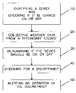
Figure 1 is a flow chart of a method of monitoring and controlling railroad
switch snow
removal devices in accordance with an embodiment of the invention;
Figure 2 is a flow chart of an alternative method of monitoring and
controlling railroad
switch snow removal devices in accordance with an embodiment of the invention;
3a
CA 02641107 2013-12-02
Figure 3 depicts the network including a plurality of railroad switch snow
removal
devices according to an embodiment of the invention;
Figure 4 is a schematic block diagram of a snow removal control unit according
to an
embodiment of the invention;
Figure 5 depicts a user interface according to an embodiment of the invention;
3b
CA 02641107 2008-07-31
WO 2007/102959 PCT/US2007/002565
Figure 6 is a schematic illustration of a fuel tank monitoring system
according to one embodiment of the invention;
Figure 7 is a schematic illustration of several possible scenarios that
are used to describe the operations of the invention;
Figure 8 is a screen shot that displays a summary of the operating
conditions of related snow melters according to an embodiment of the
invention;
Figure 9 is a screen shot that displays the detailed operating
conditions of
a selected snow melter according to an embodiment of the invention;
Figure 10 is a screen shot that displays the control modes and on/off
parameters of a selected snow melter according to an embodiment of the
invention;
Figure 11 is a screen shot that displays user rights to snow melters
according to an embodiment of the invention;
Figure 12 is a screen shot that displays fault notifications of snow
melters according to an embodiment of the invention;
Figure 13 is a screen shot that displays the location and identification
of
snow melters according to an embodiment of the invention;
Figure 14 is a schematic diagram of an embodiment of the network
according to the present disclosure; and
Figure 15 is a schematic diagram of the embodiment of the network
shown if Figure 14.
Detailed Description of the Preferred Embodiment
Referring primarily to figures 1 and 3, a method of monitoring
railroad switch snow removal devices 200 is shown. The first step includes
identifying 10 a device and checking if the device 200 (shown schematically in
figure 4) is on or off. In some embodiments the geographic location is stored
at the
base station 202 corresponding to a particular device identification number.
In
another embodiment the geographic location is stored at a memory location 301
at
snow removal device 200. The geographic location can be any number of
references. In some embodiments, the geographic location is identified as
specific
geographic coordinates (e.g., longitude and latitude), while in other
embodiments
4
CA 02641107 2008-07-31
WO 2007/102959 PCT/US2007/002565
the geographic location is identified as a particular zip code. For example,
referring
to figure 13, the snow melter is shown associated with a serial number, name,
zip
codc, latitude, longitude, region, division, subdivision, and mile post. In
some
embodiments the above information is recorded and tracked by a provider upon
installation of the snow removal devices.
Next, the base station 202 collects 20 weather data from a secondary
source 204 that corresponds to the particular identified geographic location.
Some
exemplary secondary sources for weather data include: www.weather.com,
www.cnn.com/weather/, and www.wunderground.com. Once the weather data is
queried, the base station 202 determines 30 whether the device 200 should be
on or
off and checks 40 for any discrepancy. For example, if the secondary source
indicates heavy snow at the particular geographic location, then the device
should be
on. In contrast, if the secondary source indicates that it is warm and sunny
at the
particular geographic location, the device should probably be turned off. If a
discrepancy is detected, an operator 206 is alerted 50 so that the operator
can
investigate the discrepancy.
Referring to figures 2 and 4, an alternative method of monitoring and
controlling railroad switch snow removal devices 200 is shown. The first step
includes measuring 100 operating and environmental conditions. This step, for
example, may include the step of measuring the ambient temperature, the
ambient
moisture content, and the available fuel. The next step is processing the data
112 by
comparing 120 the measured data to a predetermined set of criteria. This step
can
include comparing the data with a predetermined set of criteria saved in a
local
memory location 301 to determine if snow is falling and if the device has
enough
fuel to run properly. In some embodiments this step is accomplished locally by
the
processor 300 that is located at the snow removal device 200. In some
embodiments, depending on the rate of snowfall, the ambient temperature, and
the
available fuel, the snow removal device 200 may automatically turn on or off
as
appropriate to ensure that snow and ice do not accumulate on the rails 402 of
the
switch 400. In some embodiments the temperature of the heating or lack thereof
is
determined based on the measured criteria. For example, if the snow is
determined
to be dry and light, the heater 302 of the snow removal device 200 may be left
off to
conserve fuel and only the blower 304 will be turned on.
5
CA 02641107 2008-07-31
WO 2007/102959 PCT/US2007/002565
Referring primarily to figures 2, 3 and 4, in some embodiments if the
measured values are outside of a predetermined set of values an alert is
transmitted
116 to the base station 202. In some embodiments the base station 202 is
configured
to translate the received signal and determine, for example, whether a
particular
sensor 306, 308, 310, 312 has malfunctioned or if the device is out of fuel.
When an
alert is sent, an operator 206 can view the alert remotely when connected to
the base
station 202. In some embodiments the base station 202 is configured to page
the
operator 206 whenever a certain type of alert is received. For example, the
base
station 202 may be programmed to page the operator 206 when a snow removal
device 200 has run out of fuel and snow is falling at that particular
location. Such an
alert enables an operator 206 to anticipate the failure of the particular
switch 400 and
make alternative arrangements as necessary.
Still referring primarily to figures 2, 3 and 4, in the depicted
embodiment the base station 202 measures 100 data from the snow removal
devices
200 according to a maintenance check schedule. In some embodiments the
collection of data is accomplished by configuring the snow removal devices 200
to
periodically or continuously transmit measured data hack to the base station
202. In
other embodiments, the base station 202 is configured to query data from the
snow
removal devices 200 at certain times or on command. The base station 202 also
collects 118 a comparable set of data from a secondary source 204. It should
be
appreciated that the step of collecting data from a secondary source can occur
before, after, or simultaneously with the step of collecting data from the
devices 200.
The secondary source 204 in some embodiments includes real time weather
information. In other embodiments the secondary source includes maintenance
records, such as the last time the snow removal devices 200 were refueled.
Subsequently, the data collected from the snow removal devices 200 is compared
with the data collected from the secondary sources 204. If the datum from the
snow
removal devices 200 and the secondary sources 204 are outside of an acceptable
range, an alert is triggered at the base station.
An alert may indicate, for example, that the snow removal device 200
is apparently low on fuel, even though the secondary source 204 maintenance
records indicate that the snow removal device 200 was recently refueled. Once
alerted to the discrepancy, the operator can investigate the issue further to
determine
6
CA 02641107 2008-07-31
WO 2007/102959 PCT/US2007/002565
if the snow removal device 200 is leaking, if the secondary source 204
maintenance
records are inaccurate, or if the fuel sensor is inaccurate. If the operator
206 decides
that the measured value is inaccurate, the operator 206 can reset (e.g.,
recalibrate)
122 the sensor or otherwise dismiss 126 the alert. In some embodiments the
recalibration can be accomplished remotely, and in other embodiments the
recalibration is accomplished via the user interface 314 located locally on
the snow
removal device 200. In such embodiments the device 200 includes a receiver in
addition to the transmitter 612.
Alternatively, an alert may indicate, for example, that the measured
temperature is substantially different than the temperature collected from the
secondary weather data source that corresponds to the particular geographic
location, which is measured and stored in a memory location. Once alerted of
the
discrepancy, the operator 206 may choose to override 124 the automatic on off
control of the snow removal device 200 if appropriate, or otherwise dismiss
126 the
alert. In such embodiments the device 200 includes a receiver in addition to
the
transmitter 612. An operator 206 can check other nearby sensors or other
secondary
sources to determine whether the measured data or the queried data is more
likely
accurate.
Finally, the base station 202 can be configured to store 128 all the
dates and times that the measured data from each snow removal device 200 was
checked against data from a secondary source 204. In some embodiments the next
date and time that the measured data from that particular snow removal device
200
is check against data from a secondary source 204 is dependent on when the
last
check occurred and the outcome of the last check. In some embodiments, a
number
of different types of measured data is stored at the base station for
maintenance
purposes.
Referring primarily to figure 5, according to one embodiment of the
invention the data transmitted and processed at the base station can be
accessed via
an intern& webpage. The data can in some embodiments be graphically
represented
via icons 401, 403, 404, 406, and 408 along tracks 410 on a map displayed on a
computer screen 414. The user can check the operational parameters and the
measured data by clicking on the icon that corresponds with the snow removal
device 200 of interest. In some embodiments an alert is indicated on the map
by a
7
CA 02641107 2008-07-31
WO 2007/102959 PCT/US2007/002565
flashing icon or an icon that turns a particular color, such as orange or red.
In other
embodiments, the color of the icon 401, 403, 404, 406, and 408 corresponds
with
whether the particular corresponding snow removal device 200 is on or off or
is full
or low on fuel.
According to some embodiments the data can be accessed by the
operator 206 wirelessly on a handheld device 500. In such an embodiment the
operator can be in transit to service a particular snow removal device 200 and
access
real time data regarding the snow removal devices 200 in the field.
Referring to figure 6, an embodiment is shown where fuel tank
related data is measured to determine if the tank 600 is expected to be
operational.
To be operational the tank 600 must be able to supply fuel to the burner 604.
In the
depicted embodiment the supplied fuel 618 is in gas form (e.g., propane or
natural
gas). To enable larger amounts of fuel 602 to be stored within the tank 600,
the fuel
602 in the depicted embodiment is pressurized so that most of the fuel 602 in
the
tank 600 is in liquid form. Fuel must change phase from liquid to gas to be
effectively used. Accordingly, the mere fact that the tank 600 is not empty
does not
necessarily mean that the tank 600 is expected to be operational. Since
whether a
particular liquid will change into a gas is dependent on the temperature of
the liquid
and the pressure in the tank 600, the temperature of the fuel 602 within the
tank 600
and the pressure within the tank 600 factor into whether the tank 600 is
operational
(the colder a liquid is, the less likely the liquid will vaporize at a given
pressure). In
view of the above, as compared to only knowing the amount of fuel 602 in the
tank
600, also knowing the temperature of the fuel 602, and the pressure within the
tank
600 enables one to more accurately predict whether the tank 600 is
operational.
According to one embodiment, to accurately estimate whether the
tank 600 will be operational under certain conditions, preferably at least the
following types of data are measured: the temperature in the tank 600 or the
fuel
602 therein, the pressure within the tank 600, and the level of liquid fuel
within the
tank 600. Accordingly, to such an embodiment the system includes a temperature
sensor 606, a pressure sensor 608, and a fuel level sensor 610. It should,
however,
be appreciated that in alternative embodiments sensors measuring different
data may
be included. It should also be appreciated that alternative embodiments may
include
more or fewer sensors in part depending on the specific methodology used to
8
CA 02641107 2008-07-31
WO 2007/102959 PCT/US2007/002565
analyze the data, which will be discussed in greater detail below. It should
be
appreciated that in alternative embodiments an electric heat non-combustion
source
may be employed (e.g., electric calrod heater). Such systems could include a
system
for measuring whether the necessary electric energy exists, similar to the
fuel tank
monitoring system described above.
In the depicted embodiment the sensors are connected to a transmitter
612 that is configured to transmit the measured data to a remote base station
614 or a
network server 616 or both. In one embodiment the base station 614 uses
equations
to calculate whether or not the tank 600 is expected to be operational based
on the
measured data and known or inputted data. In other embodiments the base
station
614 relies on empirical data to make its determination regarding the
operability of
the tank 600. In yet other embodiments, a combination of empirical charts and
equations are used in the analysis. In embodiments where empirical data is
used in
the analysis, the empirical data may be stored locally on a remote database
and
accessible via a network. In the depicted embodiment the empirical data is
stored on
a remote server 616 and accessible via the interne 620. Base station 614 can
be
connected to the transmitter 612 via the cellular telephone network directly,
or via a
short range wireless communication system such as any of a variety of 802.11
wireless networks (e.g., Wi-MAX or Wi-Fi) or any radio or other wireless or
wire
communication systems.
In some embodiments the base station 614 tracks and stores the
measured data to analyze the fuel usage history. For example, in some
embodiments
the level of fuel in the tank 600 is tracked over a set period of time. Such
tracking
can be used for many purposes including, for example, determining whether the
measured data is likely accurate or inaccurate, or whether the sensors are
operable
and/or whether the tank 600 is leaking. For example, if the tracked history
indicates
that the tank 600 was initially full and has been in use for a very short
period of time
or no time at all but is now empty, the tank 600 may be leaking or the
measured data
may be inaccurate. In some embodiments the base station 614 is configured to
alert
the operator when a potential problem is detected.
The system disclosed in figure 6, may also be used by an operator in
determining the type of fuel that should be used for a particular application.
In some
embodiments the conditions, such as the expected ambient temperatures, may
make
9
CA 02641107 2008-07-31
WO 2007/102959 PCT/US2007/002565
a certain type of fuel preferable. The effectiveness and efficiency of
particular fuels
can be analyzed at the base station 614 based on the data collected by the
sensors
606, 608, and 610. It should be appreciated that many other analyses can be
conducted based on data measured by the sensors and/or data queried from a
local or
remote server 616.
Referring to figure 7, the process of determining when it is
appropriate to alert the operator of a failure or otherwise initiate the
process of
override, the operations of a failed device is illustrated. It is desirable to
avoid false
detection of device failures, which are the results of normal error. For
example, for ,
a period of time the device might be ON while it is snowing. During this
period the
operation of the system may be characterized by the upper left quadrant (i.e.,
the
device is ON and the device should be ON). The snow might stop, but for a
relatively short period of time the device might still be ON. During this
period the
operation of the system can be characterized as having moved to the lower left
quadrant (i.e., the device is ON and the device should be OFF). During this
time
period, fuel is being wasted. This might occur because the sensors on the
device, or
the empirical data, or both, are slightly off. To avoid alerting the operator
relating to
small discrepancies which in time correct themselves, the system can be set up
such
that the system must operate in the lower left state for more than an hour
before an
alert is sent to the operator or a failure is otherwise deemed. On the other
hand, the
system be might be operating in the upper left quadrant and move to the upper
right
quadrant. This would occur if snow continue to fall, but the device turns
itself off
(i.e., the device is OFF and the device should be ON). Since it is important
to
prevent railroad switch failure, the system might be set to alert an operator
or
otherwise consider the discrepancy a failure after a relatively shorter period
of time,
for example, 10 minutes instead of an hour.
Still referring to figure 7, as discussed above the time period for
acceptable discrepancies is dependent on the type of discrepancy (i.e., if the
device
is ON when it should be off versus the device is off when it should be on).
Another
factor can relate to the context (i.e., what quadrant was the device
previously
operating in). For example, there may exist reasons to set different
acceptable time
periods of discrepancies based on whether the device moves into the upper
right
quadrant from the upper left quadrant or from the lower right quadrant. If the
device
CA 02641107 2008-07-31
WO 2007/102959 PCT/US2007/002565
moves to the lower right quadrant from the upper right quadrant (i.e., it
starts from
the state where it is OFF and it should be OFF, and moves to the state where
it is
OFF but should be on), the period of time of acceptable discrepancy might be
longer
than if the device moves to the same quadrant from the upper left quadrant.
The
latter occurrence might more likely indicate a failure, whereas the former
might
more likely indicate normal sensor variations.
Referring to figures 8-13, a specific embodiment of an internet based
system is described in greater detail below. Figure 8 is a screen shot showing
a
summary of the operating condition of snow melters under the control of a
particular
user. In the depicted embodiment, the summary of the snow melters can be
organized by the user according to region, division, subdivision, mile post,
or site
group. In the depicted screen shot the designated region is North and the
designated
division is Twin Cities. Three snow melters fall within this category (i.e.,
East
Wayzata, West Delano, and West Wayzata). The subdivision, mile post, and
temperature for each of the three melters arc displayed. In addition, the
status and
whether the melters are running are also displayed. From this screen the user
can
select any one of the three snow melters for further analysis.
Figure 9 is a screen shot that corresponds with the East Wayzata
snow melter shown in figure 8. In addition to the summary information
regarding
the snow melter, detailed information relating to the control and operation
parameters are displayed. In the depicted screen shot, East Wayzata is not
running
due to the air temperature, as shown under the machine status column. Other
status
options include Idle, Running-OK, Not Running-Faulted, Not Running-Timed Out,
Not Running-Should Be-Weather, Running-Should Not Be-Weather, and
Communication Failure. In the depicted embodiment, action is called (not
running
due to air temperature) for by the Weather Watcher system, which is driven by
the
secondary source data. In the depicted embodiment the secondary source data
can
be used as a check on the local sensors and controls on the snow =her, or it
can be
used to drive the system. If the local controls and sensors are used to drive
the
action of the system, the secondary weather data is used as a check and issues
alerts
when a discrepancy is detected.
Still referring to figure 9, from this view the user can view an array of
current status data that includes: fuel tank level, temperature set points,
run time
11
CA 02641107 2008-07-31
WO 2007/102959 PCT/US2007/002565
data, air temperature, rail temperature, motor voltage, duct pressure, gas
pressure,
total gas used, motor current, etc. Also, a link is provided to view a
snapshot of the
site to enable the operator to view the site. The fuel tank level is used to
determine
if the tank needs to be refilled, and also to calculate whether the tank is
operational
based on the temperature and other factors. The motor voltage and current are
used
to determine if the snow melter motor is operational, and also if the motor is
running
optimally or likely to fail. The duct pressure and gas pressure arc used to
troubleshoot, and also used to determine if the tank is expected to be
operational. In
addition, from this view the user clicks on tabs to further investigate the
last fault
reading, the operational history, and other control settings.
Figure 10 is a screen shot that corresponds with the Controls tab of
figure 9. From this view the user can remotely operate the snow menet-. The
user
can turn on or off the snow melter, adjust the temperature set points, and
adjust the
run times. In the depicted view the snow melter is configured to turn on
continually
when the air temperature is less than one degree Fahrenheit. The air
temperature set
point can also be used to prevent the snow melter from turning on. For
example, the
system can be configured such that if a sensed temperature is above a certain
level,
the device does not turn on.
Referring to figure 11, a screen shot of the user assignment page is
shown. The user assignment function allows for different levels of access
rights to
be assigned to different operators. Some operators can be authorized only to
view
the system, and others can be authorized to edit and modify the system.
Moreover,
those who are authorized to edit and modify the system may be authorized to
edit
and modify specific aspects of the system (e.g., gas, run hours, fault counts,
and
overtemp latch). In the depicted embodiment, all of the operators have full
authorization to the system.
Referring to figure 12, a screen shot of the notification setup is
shown. The notification function allows for selective notification. Particular
types
of notification can be sent to particular users via particular means. For
example, in
the depicted embodiment, Peter Molenda is set to receive notification of fuse
2 faults
by email only, whereas Eric Schneider is set to receive fuse 1 faults via cell
phone,
temperature faults via pager, and fuse 2 faults via email and work phone. In
the
depicted embodiment, the system administrator is set to receive notification
of all of
12
CA 02641107 2008-07-31
WO 2007/102959 PCT/US2007/002565
the faults. This system enables the messages to be sent to the person who is
responsible for or best suited to dealing with the particular issue. Figure
13, as
discussed above, is used to log in the identifying information of each of the
snow
melters.
Referring to figures 14 and 15, a general overview of a particular
embodiment of a network according to the present disclosure is included below.
The
components of the network architecture include: SMC ¨ Snow Melter Controller;
RCC ¨ Remote Communications Controller; WEB ¨ Web services and portal
hosting; SQL ¨ SQL Server database; RR ¨ Railroad client accessing web
portals.
The general messaging flow scenarios are summarized below in
outline
form:
I. SMC initiated
SMC <=> RCC
= SMC detects a change of operating state (i.e. from off to running) and
initiates a conversation with the RCC.
= SMC sends a message to the RCC containing the current snow melter
operating and configuration parameters.
= RCC accepts and acknowledges the message from the SMC.
= SMC closes the conversation with the RCC after 1 minute of idle time.
= RCC captures the parameter values from the message.
RCC WEB
= RCC initiates a conversation with the WEB.
= RCC sends the current snow melter parameters to the WEB.
= WEB acknowledges the message from the RCC.
= RCC closes the conversation with the WEB immediately.
= WEB captures the parameter values from the message.
= WEB updates the SQL database with the snow melter parameter values.
WEB USER
= WEB analyzes the snow melter change of state to determine notification
requirements.
= WEB issues notification messages to railroad clients for new snow melter
conditions.
2. RCC initiated
RCC SMC
= RCC initiates a conversation with the SMC.
= RCC sends a message to the SMC containing the command number.
= SMC accepts and acknowledges the message from the RCC. Included in
the acknowledgement are all SMC parameter values.
13
CA 02641107 2008-07-31
WO 2007/102959 PCT/US2007/002565
= RCC closes the conversation with the SMC after 1 minute of idle time.
= RCC captures the parameter values from the message.
RCC '4* WEB
= RCC initiates a conversation with the WEB.
= RCC sends the current snow melter parameters to the WEB.
= WEB acknowledges the message from the RCC.
= RCC closes the conversation with the WEB immediately.
= WEB captures the parameter values from the message.
= WEB updates the SQL database with the snow melter parameter values.
WEB <g> USER
= WEB analyzes the snow melter change of state to determine notification
requirements.
= WEB issues notification messages to railroad clients for new snow melter
conditions.
3. WEB initiated
WEB .44) RCC
= WEB user presses the "Refresh Values" button on a web page.
= WEB initiates a conversation with the RCC.
= WEB sends a message to the RCC containing the command number.
= RCC accepts and acknowledges the message from the WEB.
RCC <g> SMC
= RCC initiates a conversation with the SMC.
= RCC sends a message to the SMC containing the command number.
= SMC accepts and acknowledges the message from the RCC. Included in
the acknowledgement are all SMC parameter values.
= RCC closes the conversation with the SMC after 1 minute of idle time.
= RCC captures the parameter values from the message.
RCC WEB
= RCC initiates a conversation with the WEB.
= RCC sends the current snow melter parameters to the WEB.
= WEB acknowledges the message from the RCC.
= RCC closes the conversation with the WEB immediately.
= WEB captures the parameter values from the message.
= WEB updates the SQL database with the snow melter parameter values.
WEB 4:* USER
= WEB analyzes the snow melter change of state to determine notification
requirements.
= WEB issues notification messages to railroad clients for new snow melter
conditions.
14
CA 02641107 2013-12-02
From the foregoing detailed description, it will be evident that modifications
and
variations can be made in the devices and methods of the disclosure without
departing from
the scope of the invention.