Note: Descriptions are shown in the official language in which they were submitted.
CA 02641129 2014-01-09
STARTUP GAS SUPPLY PRESSURE CONTROL DEVICE OF FUEL CELL SYSTEM
AND METHOD THEREOF
BACKGROUND OF THE INVENTION
1. Field of the Invention
[0002] The present invention relates to a device and method for controlling
the startup
of a fuel cell system.
2. Description of Related Art
[00031 A fuel cell is a device that directly converts chemical energy of a
fuel into
electrical energy by allowing reactant gases (namely, an anode gas such as
hydrogen and a
cathode gas such as air) to electrochemically react with each other. Such fuel
cells are
classified into various types of fuel cells in accordance with, for example,
the type of
electrolyte used. One type of fuel cell is a solid polymer electrolyte fuel
cell in which a solid
polymer electrolyte is used as the electrolyte.
[0004] In a solid polymer electrolyte fuel cell, the following catalytic
electrode reactions
are carried out in an anode electrode and a cathode electrode.
[00051 (1) Anode electrode: 2H2 4H+ + 4e-
10006) (2) Cathode electrode: 4H+ + 4e- + 02 ---+ 2H20
[00071 In this manner, when an anode gas (H2) is supplied to the anode
electrode, the
reaction represented by formula (1) is carried out to produce hydrogen ions
(111). The
resulting hydrogen ions (H4) permeate through (diffuse into) an electrolyte
(e.g., a solid
polymer electrolyte membrane in the case of a solid polymer electrolyte fuel
cell) in a
hydrated state and reach the cathode electrode. The reaction represented by
formula (2) is
then carried out using the hydrogen ions together with a cathode gas (for
example, air)
supplied to the cathode electrode. The reactions represented by formulas (1)
and (2) are
carried out in the electrodes, and thus the fuel cell generates electricity
which may be used
for motive force. The electricity commonly generated by a typical fuel cell is
at about 1 volt.
CA 02641129 2008-10-15
Consequently, in order to use fuel cells as a power source of an automobile, a
plurality of
fuel cells are provided in the form of a fuel cell stack in which several
hundred fuel cells are
stacked together in series. In addition, in order to use fuel cells as a power
source of an
automobile, it is desirable that the fuel cell system be capable of being
rapidly started in any
ambient environment.
100081 As represented by formula (2), a fuel cell produces moisture (1120)
in the
cathode electrode concurrently with the power generation. When the operation
of a fuel cell
is stopped in an environment at a temperature below the freezing point, and
the fuel cell is
unused for a period and then started at a temperature below the freezing
point, the water
produced may be in a state in which the water is frozen IA an electrode
catalyst or a gas
diffusion layer adjacent to the electrode catalyst. In such a state, the
electrode reaction area
is decreased, thereby significantly degrading the ability of a reactant gas to
diffuse to the
electrode catalyst. In such a case, it is known in the art that by increasing
the gas pressure of
a reactant gas supplied to the fuel cell stack, the reactant gas is more
consistently able to
reach a reaction site where a catalytic electrode reaction occurs.
BRIEF SUMMARY OF THE INVENTION
[0009] It is accordingly an object of the present invention to provide a
startup control
device of a fuel cell system and a startup control method of the fuel system
to enable the
system to startup more quickly and to attain normal operation while avoiding
flooding.
100101 In an embodiment, the invention provides a startup control device of
a fuel cell
system including a fuel cell stack having a plurality of fuel cells stacked
together, each of the
fuel cells having a membrane electrode assembly including an electrolyte
membrane
interposed between a cathode electrode and an anode electrode. The device
further includes
a gas supply unit configured to supply a gas to the fuel cell stack and a
controller configured
to control the gas supply unit based on a parameter value related to the
occurrence of
flooding of the fuel cell stack. During startup of the fuel cell stack, the
gas is supplied to the
fuel cell stack at a first supply pressure for a time period determined based
on the parameter
value, and after the time period has expired, gas is supplied to the fuel cell
stack at a second
supply pressure, the second supply pressure being less than the first supply
pressure.
2
PHIP/ 707976.1
CA 02641129 2008-10-15
100111 In another embodiment, the invention provides a fuel cell system
including a
fuel cell stack in which a plurality of fuel cells are stacked together, each
of the fuel cells
having a membrane electrode assembly including an electrolyte membrane
interposed
between a cathode electrode and an anode electrode. The device further
includes a gas
supply unit configured to supply a gas to the fuel cell stack and a controller
configured to
compare a parameter value showing the degree of variation in the voltage of
the fuel cells
with a predetermined value and to control the gas supply unit based on the
parameter value.
During startup of the fuel cell stack, when the degree of variation in the
voltage is larger
than the predetermined value, the controller controls the supply pressure of
the gas supplied
to the fuel cells so that the supply pressure is lower than the supply
pressure of the gas when
the degree of variation in the voltage is smaller than the predetermined
value.
100121 In still another embodiment, the invention provides a method of
controlling the
startup of a fuel cell system including a fuel cell stack having a plurality
of fuel cells stacked
together, each of the fuel cells having a membrane electrode assembly
including an
electrolyte membrane interposed between a cathode electrode and an anode
electrode. The
method includes supplying a gas to the fuel cell stack at a supply pressure,
determining a
time period based a parameter value related to the occurrence of flooding of
the fuel cell
stack, controlling the supply pressure during startup of the fuel cell stack
to be a first supply
pressure during the time period, and controlling the supply pressure during
startup of the
fuel cell to be a second supply pressure after the time period has expired,
the second supply
pressure being less than the first supply pressure.
BRIEF DESCRIPTION OF THE DRAWINGS
100131 The accompanying drawings, which are incorporated herein and
constitute part
of this specification, illustrate preferred embodiments of the invention, and
together with the
general description given above and the detailed description given below,
serve to explain
features of the invention.
100141 FIG. lA is a graph showing fuel cell stack output versus time during
startup as a
function of operating pressure.
100151 FIG. 1B is a graph showing the standard deviation of average voltage
output
from a fuel cell stack versus time during startup as a function of operating
pressure.
3
PHIP/ 707976.1
CA 02641129 2008-10-15
100161 FIGS. 2A and 2B are an exploded perspective view and a cross-
sectional view,
respectively, illustrating the structure of an embodiment of a fuel cell.
[0017] FIG. 3 is a diagram showing a control device of a fuel cell system
according to a
first embodiment of the present invention.
100181 FIG. 4 is a flowchart illustrating a main routine of a startup
control device of a
fuel cell system according to an embodiment of the present invention.
100191 FIGS. 5A and 5B are flowcharts showing subroutines for controlling a
startup
control device according to a first embodiment of the present invention.
100201 FIGS. 6A to 6C are graphs illustrating the operation of the startup
control device
of a fuel cell system over time according to an embodiment of the present
invention.
[0021] FIG. 7 is a diagram showing a control device of a fuel cell system
according to a
second embodiment of the present invention.
[0022] FIGS. 8A and 8B are flowcharts showing subroutines for controlling a
startup
control device according to a second embodiment of the present invention.
[0023] FIG. 9 is a graph showing the relationship between the temperature
of a fuel cell
stack at the time of startup and a reference current integrated value
according to an
embodiment of the present invention.
[0024] FIG. 10 is a diagram showing a control device of a fuel cell system
according to
a third embodiment of the present invention.
100251 FIGS. 11A and 11B are flowcharts showing subroutines for controlling
a startup
control device according to a third embodiment of the present invention.
[0026] FIG. 12 is a graph showing the relationship between the refrigerant
temperature
at the time of startup and a reference refrigerant temperature according to an
embodiment of
the present invention.
100271 FIGS. 13A and 13B are flowcharts showing subroutines for controlling
a startup
control device according to a fourth embodiment of the present invention.
[0028] FIG. 14 is a graph showing the relationship between the temperature
of a fuel
cell stack at the time of startup and a reference time according to an
embodiment of the
present invention.
[00291 FIG. 15 is a diagram showing a control device of a fuel cell system
according to
a fifth embodiment of the present invention.
4
PHIP/ 707976.1
CA 02641129 2008-10-15
[0030] FIGS. 16A and 16B are flowcharts showing subroutines for controlling
a startup
control device according to a fifth embodiment of the present invention.
[0031] FIG. 17 is a flowchart showing a main routine for controlling a
startup control
device according to a sixth embodiment of the present invention.
[0032] FIG. 18 is a graph illustrating the fuel cell stack voltage output
during startup
versus time according to a sixth embodiment of the present invention.
DETAILED DESCRIPTION
[0033] A first embodiment of the present invention will hereinafter be
described with
reference to the accompanying drawings. The present invention provides for
quick startup
of a fuel cell system. As a result of intensive studies in developing an
embodiment of the
present invention, a factor has been determined which prevents a fuel cell
system from
starting up quickly. In order to facilitate understanding of the present
invention, this finding
will be described.
[0034] FIGS. IA and 1B are graphs showing the results of experiments
performed
during startup of a fuel cell system. FIG. IA shows the change in fuel cell
stack output, and
FIG. 1B shows the variation in the average voltage of fuel cells, when the
operating pressure
(the supply pressure of a gas) is changed during startup of a fuel cell (i.e.,
during the
transient time period when operation of a fuel cell is initiated).
[0035] During startup of a fuel cell, particularly during startup of a fuel
cell at a
temperature below the freezing point, it is preferable that the supply
pressure of a reactant
gas is increased. The experimental results of FIG. lA also show that as the
supply pressure
of a reactant gas is increased, the fuel cell stack output is increased
immediately after the
operation of the fuel cell is started. However, once a certain period of time
has elapsed after
starting the operation of the fuel cell, the fuel cell stack output is not
increased further. The
studies conducted in developing the present invention have determined that
this
phenomenon is caused by flooding of the stack due to moisture produced by the
reactions
inside the fuel cells.
[0036] As shown in FIG. 1B, in the case where the operating pressure is
high, the
standard deviation of the fuel cell voltage does not change significantly
during a time period
spanning from the start of operation to a transition time, but varies
significantly at the
PH1P/ 707976.1
CA 02641129 2008-10-15
transition time to a higher level of standard deviation. The transition time
can range, for
example, from about 20 seconds to about 40 seconds, but can be longer or
shorter than these
exemplary times based on the temperature of the fuel cell stack or any number
of other
factors.
100371 The effect of flooding will be described in the context of the
structure of a fuel
cell. It is understood that a plurality of fuel cells, perhaps as many as
several hundred, each
having the structure described herein, can be stacked and held at a
predetermined surface
pressure to produce a fuel cell stack 100. FIGS. 2A and 2B illustrate the
structure of an
individual fuel cell 2. FIG. 2A is an exploded perspective view showing the
fuel cell
structure, and FIG. 2B is a cross-sectional side view of the fuel cell 2. The
fuel cell 2 has a
structure in which a cathode separator 13a is disposed on a surface of a
membrane electrode
assembly ("MEA") 10 and an anode separator 13b is disposed an opposed surface
of the
MEA 10.
[0038] The MEA 10 includes an electrolyte membrane 11, a cathode electrode
12a, and
an anode electrode 12b. The electrolyte membrane 11 is a proton-conductive ion-
exchange
membrane made of a fluorocarbon resin. The electrolyte membrane 11 exhibits a
satisfactory electrical conduction property in a wet state. Therefore, in
order to utilize the
performance of the electrolyte membrane 11 to improve the power generation
efficiency, it
is necessary to maintain an optimum moisture condition of the electrolyte
membrane 11.
Accordingly, in this embodiment, reactant gases (a cathode gas and an anode
gas) introduced
into the fuel cell are moisturized. Purified water is preferably used as water
for maintaining
the optimum moisture condition of the electrolyte membrane 11. This is because
when
water containing impurities is supplied to the fuel cell, the impurities are
accumulated on the
electrolyte membrane 11, thereby decreasing the power generation efficiency of
the fuel cell.
100391 The cathode electrode 12a is provided on a surface (shown on the
left side in
FIG. 2B) of the electrolyte membrane 11, and the anode electrode 12b is
provided on the
reverse surface (shown on the right side in FIG. 2B) thereof. Each of the
cathode electrode
12a and the anode electrode 12b includes a catalyst layer 121 and a gas
diffusion layer 122.
The catalyst layer 121 can be composed of, for example, carbon black particles
on which
platinum is supported. The gas diffusion layer 12 is composed of a member
having
satisfactory gas diffusibility and electrical conductivity properties, e.g., a
carbon fiber.
6
PH1P/ 707976.1
CA 02641129 2008-10-15
100401 The cathode separator 13a is disposed at the outside of the cathode
electrode
12a. Ribs 131 are provided so as to project from a surface of the cathode
separator 13a
toward the cathode electrode 12a, thus forming reactant gas flow paths 132
between the ribs
131. As illustrated in FIGS. 2A and 2B, four reactant gas flow paths 132 are
formed,
although any number of ribs 131 and corresponding flow paths 132 can be
created. The
cathode separator 13a is made, for example, from carbon or a metal. The anode
separator
13b is disposed at the outside of the anode electrode 12b. Ribs 131 are
provided so as to
project from a surface of the anode separator 13b toward the anode electrode
12b, thus
forming reactant gas flow paths 132 between the ribs 131. As illustrated in
FIGS. 2A and
2B, four reactant gas flow paths 132 are formed, although any number of ribs
131 and
corresponding flow paths 132 can be created. The anode separator 13b is made,
for
example, from carbon or a metal.
100411 In a fuel cell having the above-described structure, catalytic
electrode reactions
(1) and (2) are carried out in the MEA 10 (the electrolyte membrane 11, the
cathode
electrode 12a, and the anode electrode 12b), and water (H2O) is produced. The
produced
water (H20) generally becomes water vapor that is then discharged to the
outside of the fuel
cell together with the cathode gas. Alternatively, the produced water (H20) is
discharged to
the outside of the fuel cell in the form of liquid water.
[00421 However, when the temperature of the ambient environment is low, the
saturated
water vapor partial pressure decreases. Accordingly, the amount of moisture
discharged to
the outside of the fuel cell in the form of water vapor significantly
decreases. Therefore, the
produced water (H20) may remain inside the fuel cell. The excess accumulation
of water
(H20) in the fuel cell is known as flooding. If the produced water (H20) is
accumulated in
the reactant gas flow paths 132 of the cathode separator 13a, the flow of the
reactant gas
(cathode gas) degrades, thereby decreasing the catalytic reaction due to
flooding.
Furthermore, the produced water (H20) may permeate through the electrolyte
membrane 11
and may be accumulated in the reactant gas flow paths 132 of the anode
separator 13b. This
also degrades the flow of the reactant gas (anode gas), thereby decreasing the
catalytic
reaction due to flooding.
100431 In such a flooded state, the output of the fuel cell decreases, and
it takes a long
time from time of starting of the system until normal operation is achieved
(i.e., there is a
7
PHIP/ 707976. I
CA 02641129 2008-10-15
lengthy startup time period). Normal operation is considered to be a state of
fuel cell
operation in which a satisfactory electrical output can be obtained.
Furthermore, when the
temperature of the ambient environment is below the freezing point, the
produced water
(H20) remaining inside the fuel cell may freeze, and as a result, the reaction
represented by
formula (2) is inhibited. Consequently, power generation may not be performed
by the fuel
cell.
100441 The time at which this flooding phenomenon occurs and inhibits the
catalytic
reaction is different in respective fuel cells, and depends on factors
including, but not limited
to, the variation in the performance of each electrode and the variation in
the amount of
reactant gas supplied. Therefore, at the initial stage in which the flooding
phenomenon
occurs, the amount of power generation in the fuel cells varies. If a fuel
cell is maintained in
a flooded condition, the catalytic reaction is decreased in all of the fuel
cells of a stack, and
thus the electrical output of the fuel cell stack does not attain normal
operation levels. More
specifically, as shown in FIGS. IA and 1B, when a reactant gas is supplied at
a high
pressure, the stack output is high immediately after operation is started
(FIG. 1A) while the
voltage of the fuel cells varies (that is, the standard deviation of the
voltage increases) in the
course of the operation (FIG. 1B). But when operation of the fuel cell is
continued in the
flooded condition, the stack output is not increased.
100451 Accordingly, to avoid a condition whereby the flooding persists and
thus inhibits
an increase in voltage of the fuel cell stack, the occurrence of flooding is
estimated or
anticipated in advance based on a parameter value related to the occurrence of
flooding. A
high pressure gas is supplied until a time immediately before the occurrence
of flooding is
anticipated to occur, and then the pressure of the supply gas is decreased
after that time.
Thus, the time period during which the gas is supplied at a high pressure is
prolonged as
much as possible while avoiding an increase in the startup time due to
flooding in one or
more of the fuel cells. Thereby, the amount of heat of reaction in the cells
is increased to
improve the temperature of the cells and to increase performance. As a result,
the total time
required for startup (i.e., for attaining normal operation) of the fuel cell
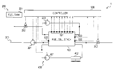
stack can be
reduced.
100461 FIG. 3 is a diagram showing a control device of a fuel cell system
according to a
first embodiment of the present invention. Each arrow shown by a solid line in
the figure
8
PHIP/ 707976.1
CA 02641129 2008-10-15
indicates a direction of a flow of a gas or the like. Each arrow shown by a
broken line in the
figure indicates a signal line. A fuel cell system 1 includes a fuel cell
stack 100, an anode
gas supply system 200, a cathode gas supply system 300, and a refrigerant
circulation system
400.
[00471 The fuel cell stack 100 includes voltage sensors 501 that detect the
voltage of
respective fuel cells, voltage sensors 502 that detect the total voltage of
the fuel cell stack
100, and a temperature sensor 503 that detects the temperature of the fuel
cell stack 100.
Signals from the voltage sensors 501, the voltage sensors 502, and the
temperature sensor
503 are inputted to a controller 500.
[0048] The anode gas supply system 200 includes a fuel tank 201, an anode
gas pressure
control valve 202, and an anode gas circulating pump 203. The opening of the
anode gas
pressure control valve 202 is adjusted in accordance with a signal from the
controller 500 to
control the pressure of an anode gas supplied to the fuel cell stack 100. The
cathode gas
supply system 300 includes a cathode gas supply pump 301 and a cathode gas
pressure
control valve 302. The opening of the cathode gas pressure control valve 302
is adjusted in
accordance with a signal from the controller 500 to control the pressure of a
cathode gas
supplied to the fuel cell stack 100. The refrigerant circulation system 400
includes a
refrigerant circulating pump 401 and a radiator 402.
[0049] A specific control logic of the controller 500 will be described
below, in
conjunction with the flowcharts in the figures. FIG. 4 is a flowchart
illustrating a main
routine for controlling the operation of a startup control device of a fuel
cell system
according to the present invention. When the controller 500 detects a start
signal, the
controller 500 executes the process shown in FIG. 4 repeatedly at
predetermined intervals
(e.g., every 10 milliseconds).
[0050] In Step Si, the controller 500 determines whether a supply gas (an
anode gas or
a cathode gas) is supplied or not supplied. When the gas is not supplied, the
process
proceeds to Step S2. When the gas is supplied, the process proceeds to Step
S4.
[0051] In Step S2, the controller 500 sets a determination value for
determining an end
time of a high pressure operation state, i.e., an operation state in which the
supply gas (the
anode gas or the cathode gas) is supplied at a high pressure. A specific
setting method will
be described below. In Step S3, the controller 500 supplies the supply gas
(the anode gas or
9
PHIP/ 707976.1
CA 02641129 2008-10-15
the cathode gas) at a high pressure, and begins a high pressure operation of
the fuel cell
stack. When the gas is supplied at a high pressure, the supply pressure of the
supply gas (the
anode gas or the cathode gas) is set to be a pressure that is preferably
higher than would be
typically supplied during normal operation. For example, the high pressure can
be a
maximum pressure that can be realized in the system, regardless of the system
temperature
at the time of startup or any number of other factors. The maximum pressure
that can be
realized in a system is commonly at least 150 kPa.
[0052] In Step S4, the controller 500 determines whether the high pressure
operation
state has finished or not. When the high pressure operation state has not yet
finished, the
process proceeds to Step S5. When the high pressure operation state has
already finished,
the process proceeds to Step S8.
[0053] In Step S5, the controller 500 determines whether or not the end
time of the high
pressure operation state has been reached. In Step S6, if the controller 500
determines that
the end time of the high pressure operation state has not been reached, the
process is
temporarily exited; if the controller 500 determines that the end time has
been reached, the
process proceeds to Step S7. In Step S7, the controller 500 stops the high
pressure operation
state and reduces the supply pressure of the supply gas (the anode gas or the
cathode gas). In
this pressure reduction, the supply pressure of the supply gas (the anode gas
or the cathode
gas) is reduced to a pressure that is preferably lower than would typically be
supplied during
normal operation. For example, the supply pressure can be reduced to a minimum
pressure
at which the operation can be performed (e.g., approximately atmospheric
pressure).
[0054] In Step S8, the controller 500 determines whether or not the
temperature Ts of
the fuel cell stack 100 exceeds a temperature Ts0 at which normal operation
can be
performed. When it is determined that the temperature Ts of the fuel cell
stack 100 does not
exceed the temperature Ts0, the process is temporarily exited. When it is
determined that the
temperature Ts of the fuel cell stack 100 exceeds the temperature Ts0, the
process proceeds
to Step S9.
[0055] In Step S9, the controller 500 switches to normal operation and sets
the supply
pressure of the supply gas (the anode gas or the cathode gas) to a normal
pressure. The
supply pressure during the normal operation is set in accordance with a load
required for the
PHIP/ 707976.1
CA 02641129 2008-10-15
system. For example, in the case of an unloaded state, a minimum pressure at
which fuel
cell operation can be performed may be set as the normal supply pressure.
[0056] FIGS. 5A and 5B are flowcharts of subroutines of a process for
controlling
startup of a fuel cell system. In the illustrated embodiment, a parameter
value showing the
degree of variation in the voltage (e.g., the standard deviation of the fuel
cell voltage for the
fuel cells in the stack) is calculated on the basis of the cell voltages of
the individual stacked
fuel cells. The operation state of the supply gas to the fuel cell stack is
varied based on this
standard deviation. FIG. 5A shows a process of determining and setting a value
of the end
time of the high pressure operation state during which the supply gas is
supplied at a high
pressure. In the illustrated embodiment, the process of setting the
determination value of the
high pressure operation end time is performed as follows. In Step S211, the
controller 500
sets a reference standard deviation or determination value ao. The reference
standard
deviation ao can be determined on the basis of, for example, the
specifications of the fuel
cell stack 100 or the temperature of the fuel cell stack 100 at the time of
startup the fuel cell
system. For example, for a fuel cell in which the single cell voltage output
in an unloaded
state is 1.0 V, the voltage of the fuel cell in a loaded state is in the range
of about 0.4 to 0.8
V. In that case, the reference standard deviation ao for determining the
degree of variation
may be set to a value, for example, in the range of about 0.01 V to 0.03 V,
which may be
varied based on the temperature at the time of startup or any number of other
factors.
[0057] FIG. 5B shows a process of determining whether the end time of the
high
pressure operation state has been reached. In the illustrated embodiment, the
process of
determining the high pressure operation end time is performed as follows. In
Step S511, the
controller 500 calculates the standard deviation a of the voltages of the fuel
cells. In Step
S512, the controller 500 determines whether or not the calculated standard
deviation a is
larger than the reference standard deviation ao. When it is determined that
the calculated
standard deviation a is smaller than the reference standard deviation ao, the
process is
temporarily exited. When it is determined that the calculated standard
deviation a is larger
than the reference standard deviation ao, the process advances to Step S513,
in which the
controller 500 determines the high pressure operation end time.
[0058] FIGS. 6A to 6C are time graphs illustrating the operation of the
startup control
device of a fuel cell system according to the present invention. In the
description below,
11
PHIP/ 707976.1
CA 02641129 2008-10-15
step numbers preceded by S of the flowcharts are also given for ease of
understanding of the
correspondence of the time graphs with the flowcharts.
[0059] When the controller 500 detects a start signal, the controller 500
sets a
determination value ao for determining an end time of an operation state in
which the supply
gas (the anode gas or the cathode gas) is supplied at a high pressure (S2 and
S211), supplies
the supply gas (the anode gas or the cathode gas) at a high pressure, and
starts a high
pressure operation (S3). Consequently, the supply pressure of the gas (the
anode gas or the
cathode gas) increases (FIG. 6C), and the output of the fuel cell stack
increases (FIG. 6A).
[0060] In the subsequent cycle and thereafter, since the supply gas has
already been
supplied, the process proceeds to Step Sl, then to Step S4, then to Step S5,
and the
controller 500 determines whether or not the end time of the high pressure
operation state
has been reached. More specifically, the controller 500 calculates the
standard deviation a
of the voltages of the fuel cells (Step S511), and a series of Step Si to Step
S4 to Step S5 to
Step S511 to Step S512 to Step S6 is repeatedly performed until the standard
deviation
becomes larger than the determination value ao.
[0061] When the standard deviation a becomes larger than the determination
value ao,
for example at a time ti as shown in FIG. 6B, the process proceeds to Step
S512 and then to
Step S513. The process further proceeds to Step S6 and then to Step S7.
Specifically, the
controller 500 stops the high pressure operation state and reduces the supply
pressure of the
supply gas (the anode gas or the cathode gas) (FIG. 6C) to a lower pressure.
[0062] In the subsequent cycle and thereafter, since the high pressure
operation has been
finished, the process proceeds to Step Si, then to Step S4, then to Step S8,
and the operation
state is maintained until the temperature Ts of the fuel cell stack 100
exceeds the
temperature Tso at which normal operation can be performed. Accordingly,
flooding can be
suppressed, which decreases the standard deviation a (FIG. 6B), and at the
same time
increases the output of the fuel cell stack (FIG. 6A).
[0063] When the temperature Ts of the fuel cell stack 100 exceeds the
temperature Tso
at which normal operation can be performed, for example at a time t, as shown
in FIG. 6B,
the process proceeds to Step S8, then to Step S9. Specifically, the controller
500 switches to
normal operation and increases the supply pressure of the supply gas to a
normal pressure
(FIG. 6C).
12
PHIP/ 707976.1
CA 02641129 2008-10-15
100641 According to this embodiment, on detecting a start signal, the
supply gas (the
anode gas or the cathode gas) is initially supplied at a high pressure.
Therefore, the
operation of a fuel cell can be started even at low temperatures (including at
cryogenic
temperatures). However, if the high pressure operation state is maintained,
flooding would
caused by water produced by the catalytic reaction, and thus it would take a
long time to
attain normal operation of the fuel cell. However, because the studies
conducted in
developing an embodiment of the present invention have determined that the
standard
deviation a of the voltages of the fuel cells is increased by an excessive
amount of produced
water, which may lead to flooding, the startup control device described herein
can avoid
flooding and reach normal operation more quickly. Accordingly, in this
embodiment, the
supply pressure of the supply gas is decreased from the high pressure
operation state on the
basis of the standard deviation a of the fuel cell voltages. Consequently, the
flooding
phenomenon caused by water produced by the catalytic reaction can be
suppressed in
advance. As a result, a high output of the fuel cell stack can be maintained,
and thus normal
operation of the fuel cell stack can be achieved in a short time.
100651 A second embodiment of the present invention will hereinafter be
described with
reference to the accompanying drawings. FIG. 7 is a diagram showing a control
device of a
fuel cell system according to a second embodiment of the present invention.
[0066] As discussed above, in the first embodiment, the voltage of each of
the fuel cells
is detected, and the standard deviation a of the voltages of the fuel cells is
calculated to
determine the degree of variation in the power generation of the fuel cells.
When the
variation is large (i.e., when the standard deviation is large), it is
determined that flooding
occurs. However, the structure of the first embodiment requires a large number
of sensors
and a high cost. Consequently, in the second embodiment, a power generation
current of the
fuel cell stack is detected, and it is anticipated that the amount of water
produced by a
catalytic reaction is increased on the basis of an increase in the integrated
value of the power
generation current.
[0067] In a fuel cell system 1 of this embodiment, a current sensor 504
detects a power
generation current of the fuel cell stack 100. FIGS. 8A and 8B are flowcharts
showing
subroutines for controlling a startup control device of the second embodiment.
FIG. 8A
shows a process of setting a determination value of the high pressure
operation state end
13
PHIP/ 707976.1
CA 02641129 2008-10-15
time. FIG. 8B shows a process of determining the high pressure operation state
end time.
The main process of the second embodiment is the same as that of the first
embodiment (as
shown in FIG. 4), but a specific determination method is different between the
second
embodiment and the first embodiment.
[0068] In the second embodiment, the process of setting the determination
value of the
high pressure operation end time is performed as follows. In Step S221, the
controller 500
sets a reference current integrated value to on the basis of a temperature Ts
of the fuel cell
stack 100 at the time of startup. Specifically, the reference current
integrated value to is set
on the basis the relationship with startup temperature depicted in of FIG. 9.
As shown in
FIG. 9, the reference current integrated value to increases as the fuel cell
stack temperature
Ts at the time of startup increases.
[0069] The current integrated value also increases as the amount of power
generation in
the fuel cell stack increases. That is, the higher the current integrated
value, the higher the
amount of power generation in the fuel cell stack, and vice-versa.
Accordingly, by detecting
the current integrated value, the amount of water produced by a reaction in
the fuel cell stack
can be estimated, and occurrence of flooding in the fuel cell stack can be
anticipated.
[0070] Therefore, in the second embodiment, the process of determining the
high
pressure operation end time is performed as follows. In Step S521, the
controller 500
detects a current value I. In step S522, the controller 500 determines a
current integrated
value I, at this time by adding the current value Ito a current integrated
value tz at the
previous time. In Step S523, the controller 500 determines whether or not the
current
integrated value I (at this time) is larger than the reference current
integrated value to.
When it is determined that the current integrated value I; (at this time) is
smaller than the
reference current integrated value to, the process is temporarily exited. When
it is
determined that the current integrated value I, (at this time) is larger than
the reference
current integrated value to, the controller 500 determines the high pressure
operation end
time (Step S524).
[0071] According to the second embodiment, in addition to the advantages of
the first
embodiment, the number of required sensors can be reduced, and thus the fuel
cell system
can be produced at a low cost.
14
PHIP/ 707976.1
CA 02641129 2008-10-15
100721 A third embodiment of the present invention will hereinafter
be described with
reference to the accompanying drawings. FIG. 10 is a diagram showing a control
device of a
fuel cell system according to a third embodiment of the present invention. In
this
embodiment, it is anticipated that the amount of water produced by a catalytic
reaction is
increased on the basis of an increase in an outlet refrigerant temperature Tc
near an outlet of
the fuel cell stack in the refrigerant circulation system 400.
100731 The refrigerant temperature increases as the heat of reaction
of the fuel cell stack
increases. That is, as the refrigerant temperature increases, it is an
indication that the
amount of power generation in the fuel cell stack has increased. Accordingly,
by detecting
= the refrigerant temperature, the amount of water produced by a reaction
in the fuel cell stack
can be estimated, and thus occurrence of flooding in the fuel cell stack can
be anticipated.
100741 A fuel cell system 1 of this embodiment includes an outlet
refrigerant
temperature sensor 505 that detects the outlet refrigerant temperature Tc in a
refrigerant flow
path near the outlet of the fuel cell stack 100. FIGS. 11A and 11B are
flowcharts showing
subroutines for controlling a startup control device of the third embodiment.
FIG. 11A
shows a process of setting a determination value of the high pressure
operation state end
time. FIG. 11B shows a process of determining the high pressure operation
state end time.
The main process of the third embodiment is the same as that of the first
embodiment (as
shown in FIG. 4), but a specific determination method is different between the
third
embodiment and the first embodiment.
100751 In the third embodiment, the process of setting the
determination value of the
high pressure operation end time is performed as follows. In Step S231, the
controller 500
sets a reference refrigerant temperature Tco on the basis of the refrigerant
temperature T.
Specifically, the reference refrigerant temperature Tco is set on the basis of
the refrigerant
response characteristics depicted in FIG. 12. As shown in FIG. 12, as the
refrigerant
temperature Tc at the time of startup of the fuel cell stack increases, the
reference refrigerant
temperature Tco increases.
100761 In the third embodiment, the process of determining the high
pressure operation
end time is performed as follows. In Step S531, the controller 500 determines
whether or
not the refrigerant temperature Tc is higher than the reference refrigerant
temperature Tco.
When it is determined that the refrigerant temperature Tc is lower than the
reference
PHIP/ 707976.1
CA 02641129 2008-10-15
=
refrigerant temperature Too, the process is temporarily exited. When it is
determined that the
refrigerant temperature Tc is higher than the reference refrigerant
temperature To), the
controller 500 determines the high pressure operation end time (Step S532).
[0077] The fuel cell system of the third embodiment is also advantageous
in that the
number of sensors required can be reduced and thus the fuel cell system can be
produced at a
low cost.
[0078] A fourth embodiment of the present invention will hereinafter be
described with
reference to the accompanying drawings. FIGS. 13A and 13B are flowcharts
showing
subroutines for controlling a startup control device of a fourth embodiment of
the present
invention. FIG. 13A shows a process of setting a determination value of the
high pressure
operation state end time. FIG. 13B shows a process of determining the high
pressure
operation state end time. The main process of the fourth embodiment is the
same as that of
the first embodiment (as shown in FIG. 4), but a specific determination method
is different
between the fourth embodiment and the first embodiment.
[0079] In the fourth embodiment, the process of setting the determination
value of the
high pressure operation end time is performed as follows. In Step S241, the
controller 500
sets a reference time to on the basis of a temperature Ts of the fuel cell
stack 100 at the time
of startup. Specifically, the reference time to is set on the basis of the
time-temperature
characteristics of a fuel cell depicted in FIG. 14. As shown in FIG. 14, the
reference time to
decreases as the temperature Ts of the fuel cell stack 100 at the time of
startup increases.
[0080] In one example, in the case where the startup temperature of the
fuel cell stack is
in the range of about -20 C to -30 C, a time in the range of about 30 seconds
to about 40
seconds can be set as the reference time to. In another example, in the case
where the startup
temperature of the fuel cell stack is in the range of about 20 C to 30 C, a
time in the range
of about 10 seconds to about 20 seconds can be set as the reference time to.
100811In the fourth embodiment, the process of determining the high pressure
operation end time is performed as follows. In Step S541, the controller 500
integrates an
elapsed time t. As described above, this routine is executed at predetermined
intervals, and
thus the elapsed time can be determined by this integrated value. In Step
S542, the
controller 500 determines whether or not the elapsed time t is larger than the
reference time
to. When it is determined that the elapsed time t is smaller than the
reference time to, the
16
PIIIP/ 707976.1
CA 02641129 2008-10-15
=
process is temporarily exited. When it is determined that the elapsed time t
is larger than the
reference time to, the controller 500 determines the high pressure operation
end time (Step
S543).
[0082] According to the fourth embodiment, the number of sensors required
can be
reduced, and thus the fuel cell system can be produced at a low cost, as
compared with the
second embodiment and the third embodiment.
100831 A fifth embodiment of the present invention will hereinafter be
described with
reference to the accompanying drawings. FIG. 15 is a diagram showing a control
device of a
fuel cell system according to a fifth embodiment of the present invention.
[0084] In the first embodiment, the voltage of each of the fuel cells is
detected, and the
standard deviation a of the voltages of the fuel cells is calculated to
determine the degree of
variation in the power generation of the fuel cells. When the variation is
large (i.e., when
the standard deviation is large), it is determined that flooding occurs.
However, flooding
occurs more easily at an end cell. Consequently, in the fifth embodiment, a
voltage Vend of
an end cell is particularly detected, and it is anticipated that the amount of
water produced by
a catalytic reaction is increased when the end cell voltage Vend significantly
deviates from an
average cell voltage Vave of the entire fuel cell stack.
[0085] A fuel cell system 1 of the fifth embodiment includes voltage
sensors 502 that
detect the total voltage of a fuel cell stack, a temperature sensor 503 that
detects the
temperature of the fuel cell stack, and a voltage sensor 506 that detects the
voltage of an end
cell.
[0086] FIGS. 16A and 16B are flowcharts showing subroutines for
controlling a startup
control device of the fifth embodiment. FIG. 16A shows a process of setting a
determination value of the high pressure operation state end time. FIG. 16B
shows a process
of determining the high pressure operation state end time. The main process of
the fifth
embodiment is the same as that of the first embodiment (as shown in FIG. 4),
but a specific
determination method is different between the fifth embodiment and the first
embodiment.
[0087] In the fifth embodiment, the process of setting the determination
value of the
high pressure operation end time is performed as follows. In Step S251, the
controller 500
sets a reference difference in voltage AV . This reference difference in
voltage AV can be
17
PHIP/ 707976.1
CA 02641129 2008-10-15
determined, for example, on the basis of the temperature of the fuel cell
stack 100 at the
time of startup.
[0088] In the fifth embodiment, the process of determining the high
pressure operation
end time is performed as follows. In Step S551, the controller 500 detects a
total voltage
Vail of the fuel cell stack. In Step S552, the controller 500 calculates the
average voltage
Vave by dividing the total voltage Vail of the fuel cell stack by the number
of cells n.
[0089] In Step S553, the controller 500 detects the voltage Vend of an end
cell of the fuel
cell stack. In Step S554, the controller 500 determines whether or not the
absolute value of
the difference in voltage between the average voltage Vave and the end cell
voltage Vend is
larger than the reference difference in voltage AV . When it is determined
that the absolute
value is smaller than the reference difference in voltage AVO, the process is
temporarily
exited. When it is determined that the absolute value is larger than the
reference difference
in voltage AV , the controller 500 determines the high pressure operation end
time (Step
S555).
[0090] The fuel cell system of the fifth embodiment is advantageous in that
the number
of sensors required can be reduced and thus the fuel cell system can be
produced at a low
cost. In addition, flooding occurs particularly easily in an end cell.
Therefore, according to
the structure of this embodiment, an increase in the amount of water produced
by a catalytic
reaction can be anticipated with high accuracy, a flooding phenomenon caused
by water
produced by the catalytic reaction can be suppressed in advance, and normal
operation of the
fuel cell stack can be achieved in a short time.
[0091] A sixth embodiment of the present invention will hereinafter be
described with
reference to the accompanying drawings. FIG. 17 is a flowchart showing a main
routine for
controlling a startup control device of a sixth embodiment of the present
invention.
[0092] The sixth embodiment is basically the same as the first embodiment.
However,
in Step S72, the controller 500 stops the high pressure operation and
decreases the supply
pressure of the supply gas (the anode gas or the cathode gas), and increases
the flow rate of
the cathode gas. When the flow rate of the cathode gas is increased in this
manner, the
output of the fuel cell stack can be increased, as shown in FIG. 18.
Accordingly, the
operation of the fuel cell stack can be started rapidly and in a short time,
as compared with
the above-described other embodiments.
18
PHIP/ 707976.1
CA 02641129 2008-10-15
[0093] The embodiments described above can be used to control either the
cathode side
or the anode side of a fuel cell. However, the invention described above is
preferably used
at the cathode side, which is generally more affected by produced water.
100941 While the invention has been disclosed with reference to certain
preferred
embodiments, numerous modifications, alterations, and changes to the described
embodiments are possible without departing from the sphere and scope of the
invention, as
defined in the appended claims and equivalents thereof. Accordingly, it is
intended that the
invention not be limited to the described embodiments, but that it have the
full scope
defined by the language of the following claims.
19
PHIP/ 707976.1