Note: Descriptions are shown in the official language in which they were submitted.
CA 02641195 2008-10-16
226716
GAS TURBINE ENGINE COMBUSTOR AND METHOD FOR
DELIVERING PURGE GAS INTO A COMBUSTION CHAMBER OF
THE COMBUSTOR
BACKGROUND
The field of this invention relates generally to gas turbine engine
combustors,
and more particularly to ferrules for mounting engine components in
communication
with the combustion chamber of such combustors.
Gas turbine engines such as those used as aircraft engines typically have a
combustor defining an internal combustion chamber in which fuel is combusted.
One
or more components, including without limitation fuel nozzles and igniters,
are held
in communication with the internal combustion chamber by being mounted on the
combustor housing by a suitable ferrule and extending through the housing into
the
combustion chamber. Conventional ferrules (and therefore the components
mounted
on the combustor by such ferrules) are commonly moveable relative to the
housing to
allow for tolerance stackup and thermal growth of various operating components
of
the engine.
An annular space or cavity within the internal combustion chamber
surrounds the portion of the component that extends through the ferrule into
the
chamber. Due to aerodynamics within the combustion chamber, fuel can enter
into
this annular cavity and burn, thereby increasing the temperature of the
component and
increasing the risk of damage to the component and/or to the combustor
housing. To
this end, it is known to provide a ring of uniformly spaced and sized openings
(typically referred to as purge gas openings or cooling air openings) in the
ferrule at a
transverse location relative to the portion of the engine component that
extends into
the chamber such that purge gas (usually air) flows into the combustion
chamber via
the purge gas openings at the annular cavity surrounding the component to
purge the
cavity of trapped fuel and/or to cool the component within the combustion
cha.mber.
As the combustion chamber heats up, tolerance stackup and relative thermal
growth of the various components of the combustor cause the ferrule and the
-1-
CA 02641195 2008-10-16
226716
component mounted thereby to move or become repositioned transversely relative
to
the combustor housing. Such movement results in the annular cavity surrounding
the
portion of the ferrule mounted component within the combustion chamber to
substantially narrow along a region of the annular cavity and to substantially
widen
along an opposite region of the annular cavity. Along the widened region of
the
cavity the single ring of purge gas openings is no longer sufficient to direct
enough air
into the cavity to purge the cavity of trapped fuel.
There is a need, therefore, for a gas turbine engine combustor having one or
more ferrules that more effectively allow for purging of trapped fuel
surrounding
components that are mounted by the ferrule and extend into the combustion
chamber
of an engine throughout the range of movement of the ferrule during operation
of the
engine.
SUMMARY
In one aspect, a combustor for a gas turbine engine generally comprises a
housing at least in part defining an internal combustion chamber of the
combustor, a
combustor component held in communication with the combustion chamber, and a
ferrule generally coupled to the housing and being moveable relative thereto
between
a first position and a second position. The ferrule has a primary opening
through
which the combustor component extends for support of the combustor component
by
the ferrule such that the combustor component is moveable conjointly with the
ferrule
relative to the housing. The ferrule further has a plurality of purge gas
openings
formed therein separate from and in transversely spaced relationship with the
primary
opening to allow purge gas to flow through the ferrule into the combustion
chamber.
The purge gas openings are located in the ferrule such that in the first
position of the
ferrule the purge gas openings comprise at least one blocked purge gas opening
that is
blocked against the flow of purge gas therethrough into the combustion chamber
and
at least one unblocked purge gas opening through which purge gas is permitted
to
flow into the combustion chamber. And in the second position of the ferrule at
least
one of the blocked purge gas openings of the first ferrule position is
unblocked to
permit the flow of purge gas therethrough into the combustion chamber.
-2-
CA 02641195 2008-10-16
226716
A ferrule assembly according to one aspect thereof for mounting a combustor
component on a combustor housing of a gas turbine engine generally comprises a
ferrule mount secured to the housing to remain generally stationery relative
thereto
during operation of the gas turbine engine. A ferrule is mounted on the
ferrule mount
for transverse sliding movement relative thereto between a first transverse
ferrule
position and a second transverse ferrule position. The ferrule has a primary
opening
for receiving the combustor component therethrough for conjoint transverse
movement with the ferrule relative to the ferrule mount. The ferrule further
has a
plurality of purge gas openings formed therein separate from and in
transversely
spaced relationship with the primary opening to allow purge gas to flow
through the
ferrule into the combustion chamber. The purge gas openings are located in the
ferrule such that in the first position of the ferrule the purge gas openings
comprise at
least one blocked purge gas opening that is blocked by the ferrule mount
against the
flow of purge gas therethrough into the combustion chamber and at least one
purge
gas opening unblocked by the ferrule mount and through which purge gas is
permitted
to flow into the combustion chamber. And in the second position of the ferrule
at least
one of the blocked purge gas openings of the first ferrule position is
unblocked by the
ferrule mount to permit the flow of purge gas therethrough into the combustion
chamber.
In aspect of a method for directing purge gas into a combustion chamber of a
gas turbine engine combustor, a flow of purge gas is directed to a ferrule of
the
combustor. At least one of the purge gas openings is blocked in a first
position of the
ferrule to inhibit the flow of purge gas therethrough while a plurality of
other purge
gas openings remains unblocked to permit the flow of purge gas therethrough
into the
combustion chamber. At least one blocked purge gas opening is subsequently
unblocked upon movement of the ferrule to a second position thereof.
BRIEF DESCRIPTION OF THE DRAWINGS
Figure 1 is a schematic of one embodiment of a gas turbine engine including
a combustor having an internal combustion chamber;
-3-
CA 02641195 2008-10-16
226716
Figure 2a is a cross-section of a portion of the combustor including a
combustor housing which defines the internal combustion chamber of the
combustor,
a ferrule and a fuel conduit mounted by the ferrule on the combustor housing
for
transverse movement of the ferrule and fuel conduit relative to the housing,
with the
ferrule and fuel conduit illustrated in a first, generally centered position
relative to the
housing;
Figure 2b is a cross-section similar to Fig. 2a with the ferrule and fuel
conduit illustrated in a second, generally maximum transverse offset position
relative
to the housing;
Figure 3 is a perspective of the ferrule illustrating a plurality of purge gas
openings extending longitudinally through the ferrule; and
Figures 4a, 4b, 4c, 4d and 4e are schematic illustrations of the interior end
of
the ferrule with the ferrule at various transverse offset positions relative
to the
housing.
Corresponding reference characters indicate corresponding parts throughout
the drawings.
DETAILED DESCRIPTION
Referring now to the drawings and in particular to Figure 1, one embodiment
of a gas turbine engine is illustrated schematically and indicated generally
at 21. Gas
turbine engine 21 comprises a fan assembly (indicated generally at 23), a high
pressure compressor 25, a combustor 27, a high pressure turbine (indicated
generally
at 29), a low pressure turbine 31, and a booster 22. Fan assembly 23 includes
an array
of fan blades 24 extending radially outward from a rotor disc 26. Engine 21
also has
an intake side indicated generally at 28, an exhaust side indicated generally
at 30, and
longitudinal, or rotation axis 32.
In operation, air flows along an engine rotation axis 32 through fan assembly
23 and compressed air is supplied to the high pressure compressor 25. The
highly
-4-
CA 02641195 2008-10-16
226716
compressed air is delivered to combustor 27. Air from combustor 27 drives
turbines
29, 31 which in turn drive fan assembly 23.
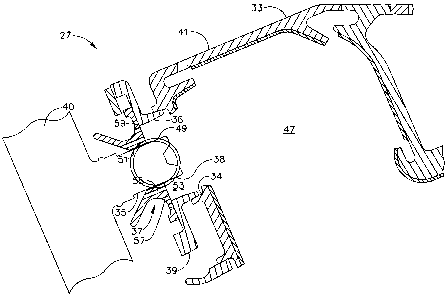
Figure 2a is a cross-section of a portion of combustor 27 including one
embodiment of a ferrule, generally indicated at 37. In general, combustor 27
comprises a housing 33 configured to define an internal combustion chamber 47
in
which the combustion of fuel occurs during operation of the engine 21.
Combustor
housing 33 as that term is used herein refers to one or more structural
components of
combustor 27 configured to singly or collectively define internal combustion
chamber
47. For example, in the illustrated embodiment of Fig. 2a combustor housing 33
comprises an annular outer liner 41, an annular inner liner (not shown) and a
domed
end indicated at 48 together at least in part defining combustion chamber 47
having a
generally annular shape.
Housing 33 further comprises a suitable ferrule mount 39 (also commonly
referred to as a ferrule tower) disposed at an opening 34 in combustor housing
33.
Ferrule mount 39 mounts ferrule 37 on combustor housing 33 generally at
opening 34
in housing 33. More suitably, ferrule 37 is mounted on combustor housing 33
for
transverse movement of ferrule 37, and more particularly transverse sliding
movement
of ferrule 37, relative to ferrule mount 39 (and more broadly, relative to
combustor
housing 33). As illustrated in Figs. 2a and 3, ferrule 37 has a central or
primary
opening 51 extending longitudinally therethrough for mounting a combustor
component such as a fuel conduit 35 that extends through housing opening 34
(which
in the illustrated embodiment is further defined by a central opening 36 in
ferrule
mount 39) and has a terminal end portion 38 that projects into combustion
chamber
47.
For purposes of further describing the present embodiment, combustor
component 35 is illustrated in the drawings and described herein as being a
fuel
conduit (and more particularly a fuel nozzle) which is in flow communication
with a
fuel source (not shown) and suitable delivery line 40 and extends through
primary
opening 51 of ferrule 37 to mount fuel conduit 35 on combustor housing 33. It
is
understood, however, that ferrule 37 may be used to mount other combustor
components on combustor housing 33 to extend through combustor housing 33 into
-5-
CA 02641195 2008-10-16
226716
combustion chamber 47 without departing from the scope of this invention. For
example, in other embodiments ferrule 37 may mount a fuel igniter (not shown)
through primary opening 51 of ferrule 37 for extension through combustor
housing 33
into combustion chamber 47. It is contemplated that a plurality of ferrules
similar to
ferrule 37 may be used to mount multiple combustor components, such as
multiple
fuel conduits 35 and/or multiple igniters on the combustor housing 33.
With continued reference to Figs. 2a and 3, the illustrated ferrule 37 is
generally annular in cross-section to define central or primary opening 51.
Mounting
fuel conduit 35 on ferrule 37 within primary opening 51 allows for conjoint
transverse
sliding movement of fuel conduit 35 with ferrule 37 relative to combustor
housing 33.
This transverse movement accommodates tolerance stackup and thermal growth
caused by temperature changes of and temperature differentials between various
components of gas turbine engine 21. For example, because engine operating
conditions can vary considerably from start-up to long duration operation,
various
components of engine 21 heat-up at different rates and the tolerance stackup
and
thermal growth that occur can vary among parts and/or throughout the duration
of
operation. As such, the transverse position of ferrule 37 (and hence fuel
conduit 35)
relative to combustor housing 33, and more particularly relative to ferrule
mount 39
can vary from use to use an/or during operation of engine 21.
With particular reference to Fig. 2a, ferrule 37 (and hence fuel conduit 35)
is
nominally positioned in a generally centered position (broadly, a first
position)
relative to ferrule mount 39 in which primary opening 51 of ferrule 37 (and
fuel
conduit 35 extending therethrough) is concentric with opening 34 in combustor
housing 33, and more particularly with central opening 36 of ferrule mount 39.
It is
understood, however, that ferrule 37 may be nominally positioned relative to
ferrule
mount 39 such that ferrule primary opening 51 is other than concentric with
ferrule
mount opening 36 without departing from the scope of this invention.
Ferrule 37 is suitably mounted on ferrule mount 39 for transverse sliding
movement relative thereto from the nominal or centered (e.g., first) position
to a
maximum transverse position as illustrated in Fig. 2b at which ferrule mount
39 or
other suitable stop structure limits further transverse movement of ferrule
37. Ferrule
-6-
CA 02641195 2008-10-16
226716
mount 39 or other stop structure in one particularly suitable embodiment is
configured
to permit equal maximum transverse movement of ferrule 37 in any direction
relative
to its centered position. It is contemplated, however, that ferrule mount 39
or other
stop structure may instead be configured such that the maximum transverse
position
of ferrule 37 upon movement in one direction is different from the maximum
transverse position of ferrule 37 upon movement in another direction.
For description purposes, the maximum transverse position of ferrule 37 as
illustrated in Fig. 2b is broadly referred to herein as a second position of
ferrule 37
that is different from, i.e., transversely offset or spaced from, the first
position of
ferrule 37. It is understood, however, that ferrule 37 is moveable
transversely relative
to ferrule mount 39 to substantially any second position along a maximum range
of
transverse movement of ferrule 37 between the first, centered position of
ferrule 37
and the maximum transverse position thereof.
Referring again to Figure 2a, end portion 38 of fuel conduit 35 extending into
combustion chamber 47 has an outer surface 49 that together with combustor
housing
33 (and more particularly with ferrule mount 39 in the illustrated embodiment)
defines an annular gap or cavity 53 surrounding fuel conduit 35 within
combustion
chamber 47. Upon transverse sliding movement of ferrule 37 relative to ferrule
mount 39, cavity 53 substantially narrows in the direction of movement of
ferrule 37
as illustrated in Fig. 2b while cavity 53 substantially widens in the
direction opposite
the direction of movement of ferrule 37.
A plurality of purge gas openings 55, 57, 59 are formed in ferrule 37 and
extend longitudinally therethrough as illustrated in Figs. 2a and 3. The purge
gas
openings 55, 57, 59 communicate at an outer end (relative to combustion
chamber 47)
of ferrule 37 with a source (not shown) of purge gas, such as pressurized air
flowing
through the engine, to direct gas flow through openings 55, 57, 59 toward an
inlet end
of ferrule 37 facing in toward combustion chamber 47. In one particularly
suitable
embodiment, as illustrated in Figs. 2a and 3, a first set of purge openings 55
is formed
in ferrule 37 in a generally ring-like pattern about primary opening 51 of
ferrule 37.
-7-
CA 02641195 2008-10-16
226716
Purge gas openings 55 are uniformly spaced from each other and are
transversely spaced from primary opening 51 of ferrule 37 (and hence the
portion of
fuel conduit 51 extending into combustion chamber 47) a uniform distance. More
suitably, purge gas openings 55 are transversely spaced from primary opening
51 of
ferrule 37 a distance less than the maximum range of transverse movement of
ferrule
37 relative to ferrule mount 39 (i.e., relative to combustor housing 33) so
that purge
gas openings 55 open into combustion chamber 47 and more particularly the
annular
cavity 53 regardless of the transverse position of ferrule 37 as illustrated
in Fig. 2b.
That is, this first set of purge gas openings 53 remains unblocked by ferrule
mount 39
upon movement of ferrule 37 through its full range of transverse movement
relative to
ferrule mount 39.
A second set of purge gas openings 57 also form a ring-like pattern about
primary opening 51 of the ferrule (and hence fuel conduit 35) with the ring-
like
pattern generally concentric with and spaced transversely outward from the
ring-like
pattern formed by first set of purge gas openings 55. As illustrated best in
Fig. 4a,
purge gas openings 57 are uniformly spaced from each other and spaced
transversely
a uniform distance from primary opening 51 of ferrule 37 in which this
distance is
greater than the transverse distance of purge gas openings 55 from ferrule 37.
In one particularly suitable embodiment the transverse distance of second set
of purge gas openings 57 from ferrule primary opening 51 is such that in the
nominal
or center position of ferrule 37 relative to ferrule mount 39 all purge gas
openings 57
open into annular cavity 53 (i.e., are unblocked by ferrule mount 39).
However, the
spacing of purge gas openings 57 from ferrule primary opening 51 is also such
that
transverse movement of ferrule 37 results in some purge gas openings 57
becoming
blocked by ferrule mount 39 to inhibit purge gas from passing through such
blocked
openings as illustrated in Fig. 2b and Figs. 4b-4e.
A third set of purge gas openings 59 is formed in ferrule 37 to form a
generally ring-like pattern concentric with the patterns formed by first set
of purge gas
openings 55 and second set of purge gas openings 57. Purge gas openings 59 are
uniformly spaced from each other and are spaced a uniform transverse distance
from
-8-
CA 02641195 2008-10-16
226716
ferrule primary opening 51 (and hence fuel conduit 35) greater than the
transverse
distance of purge gas openings 57 from primary ferrule opening 51.
In one particularly suitable embodiment the distance that third set of purge
gas openings 59 is from ferrule primary opening 51 is such that in the nominal
or
centered position of ferrule 37 (Figs. 2a and 4a) relative to ferrule mount 39
all purge
gas openings 59 are blocked by ferrule mount 39 to inhibit purge gas from
passing
through such blocked openings. However, the spacing of purge gas openings 59
from ferrule primary opening 51 is also such that transverse movement of
ferrule 37
results in some purge gas openings 59 becoming unblocked by ferrule mount 39
and
open to annular cavity 53 as illustrated in Figs. 2b and 4e.
As best seen in Fig. 4e, purge gas openings 55 and 59 are generally in radial
alignment with each other, i.e., a line drawn radially through ferrule 37 from
the
center of its primary opening 51 can pass through both purge gas openings 55
and
purge gas openings 59. Purge gas openings 57 are circumferentially offset from
purge
gas openings 55, 59 so that purge gas openings 57 do not lie on such a
radially drawn
line. Thus, it is to be understood that in Figs. 2a and 2b all three sets of
purge gas
openings 55, 57, 59 are illustrate for discussion purposes only in that where
the first
and third sets of purge gas openings 55, 59 are visible in a cross-section of
ferrule 37,
second set of purge gas openings 57 would otherwise not be visible. It is
contemplated, however, that purge gas openings 57 may be located to lie on a
common radially drawn line, or no purge gas openings 55, 57, 59 may lie on a
common radially drawn line, without departing from the scope of this
invention.
Figures 4a-4e illustrate operation of combustor 27, and more particularly
ferrule 37 at various transverse positions of ferrule 37 relative to ferrule
mount 39
(and more broadly, relative to combustor housing 33). In Fig. 4a, ferrule 37
and
hence the fuel conduit 35 is in its nominal or central position relative to
ferrule mount
39. In this position, both the first set of purge gas openings 55 and the
second set of
purge gas openings 57 are unblocked by ferrule mount 39 to permit the flow of
purge
gas therethrough into combustion chamber 47 at the annular cavity 53
surrounding
fuel conduit 35. At least one purge gas opening 55, 57, 59 is blocked in this
first,
central position of ferrule 37. For example, in the illustrated embodiment the
entire
-9-
CA 02641195 2008-10-16
226716
third (i.e., transversely outermost) set of purge gas openings 59 is blocked
by ferrule
mount 39 to inhibit purge gas flow through purge gas openings 59.
Figures 4b, 4c and 4d illustrate ferrule 37 at increasingly transverse offset
positions of ferrule 37 (and hence fuel conduit 35) relative to ferrule mount
39. In
particular, ferrule 37 has moved generally upward relative to ferrule mount
39. As a
result, annular cavity 53 surrounding the portion of fuel conduit 35 that
extends into
combustion chamber 47 becomes narrower above fuel conduit 35 (i.e., in the
upward
direction of movement of ferrule 37) and becomes wider below fuel conduit 35
(i.e.,
opposite the upward direction of movement of ferrule 37). At the transverse
position
illustrated in Fig. 4b, some purge gas openings 57 become blocked by ferrule
mount,
thereby inhibiting purge gas flow through such openings 57. All (innermost)
purge
gas openings 55 remain unblocked.
At the increased transverse offset ferrule 37 position of Fig. 4c, additional
purge gas openings 57 have become blocked by ferrule mount 39 above the
primary
opening 51 of ferrule 37 and fuel conduit 35. Because annular cavity 53 is
substantially narrowed above fuel conduit 35, a reduced number of purge gas
openings is needed to purge gas from this region of annular cavity 35. Below
fuel
conduit 35, annular cavity 53 substantially widens, thereby requiring an
additional
volume of purge gas to purge this larger volume region of annular cavity 53.
Accordingly, some purge gas openings 59 of third set of purge gas openings 59
become unblocked by ferrule mount 39 in the widened region of annular cavity
53.
Figure 4d illustrates ferrule 37 in a greater transverse offset position than
in Fig. 4c,
with even more of the purge gas openings 57 becoming blocked above fuel
conduit 35
while additional purge gas openings 59 become unblocked below fuel conduit 35
in
accordance with the widening region of the annular cavity 53. Again, all
(innermost)
purge gas openings 55 remain unblocked.
Figure 4e (as well as Fig. 2b) illustrates ferrule 37 in its maximum
transverse
offset position, i.e., as limited by ferrule mount 39 or other stop structure.
Many
purge gas openings 57 are blocked in this position while a substantial number
of
(outermost) purge gas openings 59 have become unblocked in accordance with the
substantially widened region of annular cavity 53 below fuel conduit 35.
-10-
CA 02641195 2008-10-16
226716
It will thus be seen that in any transverse position of ferrule 37 between its
nominal or center position and its maximum transverse position at least one
purge gas
opening 55, 57, 59 is blocked against the flow of purge gas therethrough into
combustion chamber 47 and at least one other purge gas opening 55, 57, 59 is
unblocked to permit the flow of purge gas into combustion chamber 47. The
first set
of purge gas openings 55, however, remains entirely unblocked throughout the
full
range of transverse movement of ferrule 37.
The cross-sectional areas of purge gas openings 55, 57, 59 are generally
equal in the illustrated embodiment. It is understood, however, that the purge
gas
openings 55, 57, 59 may be of different cross-sectional areas, such as the
cross-
section area of purge gas openings 55 being different from that of purge gas
openings
57 and/or purge gas openings 59.
In one particularly suitable embodiment, the cross-sectional areas of purge
gas openings 55, 57, 59, the number of purge gas openings 55, 57, 59, and
transverse
distance from primary opening 51 of ferrule 37 cooperate together such that a
total
purge gas flow-through area of ferrule 37 varies by less than or equal to
about 15
percent throughout the entire range of transverse movement of ferrule 37
relative to
ferrule mount 39, more suitably less than or equal to about 10 percent, and
even more
suitably less than or equal to about 5 percent. As used herein, the total
purge gas
flow-through area of the ferrule refers to the sum of the cross-sectional
areas of all the
unblocked purge gas openings 55, 57 and 59 at a given transverse position of
ferrule
37 plus the cross-sectional areas of all unblocked portions of partially
unblocked
purge gas openings 55, 57 and 59.
In operation, air flows through fan assembly 23 and compressed air is
supplied to high pressure compressor 25. The highly compressed air is
delivered to
combustor 27. Airflow from combustor 27 drives turbines 29 and 31, and turbine
31
drives fan assembly 23.
Air blows through unblocked purge gas openings 55, 57, 59 and carries fuel
trapped in annular cavity 53 downstream to be burned in combustion chamber 47.
When the ferrule 37 (and the combustion component 35 as well) is in the first
(center)
-11-
CA 02641195 2008-10-16
226716
position shown illustrated in Figures 2a and 4a, the annular cavity 53 is
sufficiently
purged of trapped fuel by the first and second purge gas openings 55 and 57.
As
tolerance stackup and thermal growth cause ferrule 37 to become transversely
offset
from the first (center) position, e.g., at a second position relative to
ferrule mount 39
as depicted in Figs. 4c, 4d and 4e the third set of purge gas openings 59 is
needed to
allow sufficient air to flow through annular cavity 53 to keep it purged of
trapped fuel.
By maintaining the total flow-through area of the ferrule relatively constant
(e.g., within about 15 percent, more suitably within about 10 percent and even
more
suitably within about 5 percent), i.e., by blocking some purge gas openings
55, 57, 59
while unblocking others upon transverse movement of ferrule 37, a ratio of air
flow
rate to total flow-through area of ferrule 37 enables a desired air velocity
into
combustion chamber 47, and a desired fuel-to-air ratio in combustion chamber
47 to
be substantially maintained throughout the full range of transverse movement
of
ferrule 37 relative to ferrule mount 39. It is contemplated that doing so may
provide a
drop in gas temperature in the vicinity of the fuel conduit 35 (broadly,
combustor
component 35).
It is understood, then, that while ferrule 37 as illustrated and described
herein
includes three sets or rings of purge gas openings 55, 57, 59, ferrule 37 may
have two
sets of purge gas openings, or more than three sets of purge gas openings,
without
departing from the scope of this invention. It is also contemplated that purge
gas
openings 55, 57, 59 need not be arranged in ring-like patterns. For example,
purge
gas openings 55, 57, 59 may have transversely staggered positions and remain
within
the scope of this invention.
While the ferrule shown and described herein is used in connection with
mounting the fuel conduit on the combustor housing, it is understood that the
ferrule
may be used to mount other combustor components on the housing for extension
into
the combustion chamber. For example, one or more igniters, the construction
and
operation of which is known to those skilled in the art, for igniting fuel
into a
combustion chamber may be mounted onto a housing by a ferrule similar to that
shown and described herein. Another example is an afterburner, the
construction and
-12-
CA 02641195 2008-10-16
226716
operation of which is known to those skilled in the art, and which may be
mounted
onto a housing by a ferrule similar to that shown and described herein.
When introducing elements of the present invention or preferred
embodiments thereof, the articles "a", "an", "the", and "said" are intended to
mean that
there are one or more of the elements. The . terms "comprising", "including",
and
"having" are intended to be inclusive and mean that there may be additional
elements
other than the listed elements.
As various changes could be made in the above constructions and methods
without departing from the scope of the invention, it is intended that all
matter
contained in the above description and shown in the accompanying drawings
shall be
interpreted as illustrative and not in a limiting sense.
-13-