Note: Descriptions are shown in the official language in which they were submitted.
CA 02641328 2008-07-31
WO 2007/088353 PCT/GB2007/000323
A Cutting Insert
Field
This invention relates to cutting inserts for machine tools
such as reamers and borers and to a method of securing a
cutting insert to a machine tool.
Background of the Invention
Diamond is the hardest, and therefore, the most abrasion
resistant of all materials and some cutting tips or blade
edges for machine tools are formed from diamond powder which
may be formed into polycrystalline diamond(PCD) which is
extremely hard and has good abrasion resistance as compared
with carbide cutting tools.
PCD is a composite of individual diamond crystals sintered
together in an inter-connected network. The PCD crystals may
be sintered directly onto a cutting tool such as a rotary
cutter as is shown in EPO 0528243A.
PCD is also available in round blanks comprising a first
phase of PCD formed a second phase of sintered tungsten
carbide. The blanks are made by applying ultra high pressure
and a high temperature to a layer of diamond powder on a bed
of a metal carbide, nitride or carbonitride powder
substrate. The metallic second phase infiltrates from the
cemented carbide substrate into the interstitial regions
between diamond crystals during the process and bonds the
diamonds together. The resultant blank combines an extremely
hard PCD surface bonded to a carbide substrate. All this is
CA 02641328 2008-07-31
WO 2007/088353 PCT/GB2007/000323
2
a...-....a1...-.a = no nnno^r 7GT
,.
\A~~41111C1A .l.ll VJ-~ G"t V V I JJ t1.
PCu bianixs are very expensive and tfle rGu bIanlx is tnen
LyYicaiiy cut into a nunAber of smaii portions whicn may be
,D mounzed directly onto cuccing tools by brazing as is snown in
1-11
Lm1n7J%~%J~-CT'Y= VVW4V~r~ 411.L..'ti. 11Qa~' Q aA1..7QdVQl1l~,.Qy~G .L11
l}..11G4 4- 4-U
wiioie covi ilYust be discarded or factory serviced once ihe PCD
tooi tip is worn or damaged.
lv .in furUn.er ciisadvantage o= -cne FCD bI.ank maceriai is znaz tne
i......: ~, ' ,..=J-.: _....., 1......: 4- 4-1 .-, a 1.. ,..-.,. = F
L...:..~.,..L..a J-..
lilCl44Jt1Q1 lO rC.l.pl,=_1.V'4"'.1.~/__ 3.=l111-41G alll.i 1llQy l/1CG~M1. -
~~-~- su~J~~+4C1.A 4lJ
t.ooi ciamping loads. In ano"c.izer cievei.opment. a rCD -cooi tip is
welded or brazed on a supporting body wnicn in turn is
secured to a zooi nead by mechanicai means. This arrangemen'c
, ~ ,. ,. . . , ,a. ,, ., ,.,
~ , .~
,
1.J 1~.~l',~}u.LG.,~ ~ 41ip1.. Qily i.,LCllutJllly LVGU4 t~rG a1_.Clnell l,
.,Jy_ L.alG' .UV~.Il/ Vl. l.ll~
lnsert arlci also permits the interchange of the insert. Sucil
an insert is avaiiabie from the present applicants.
Another known insert is shown in DE 4422 861 which discloses
1) .a-.~~ 1_ t. - nnn 4-4 ,, a a . ~ a. a ., ' ,..=
.j V G 4U441i1y .Lils~r 4 11(LVJiily rUIJ 1..1ps lJ1.QzC~A Vll1..V ~ 1..10~.1
QnI.L Wllilill
is re-orientaLabie in Une L.ooi aiiowing eacn tip to be used
in turn.
The weicxing or brazing of PCD tips onto a supporting body is
?,.~.~ an expensive Gpe=ation ailu tlie tips 1Tiust ue accurately groi=iild
after tne welciing process.
CA 02641328 2008-07-31
WO 2007/088353 PCT/GB2007/000323
3
Object of the present Invention
The present invention seeks to provide an improved and more
economically manufactured PCD cutting insert for a machine
tool.
Statements of Invention
According to the invention there is provided a cutting insert
for a machine tool comprising a flat blade formed from
polycrystalline diamond material and having a front face
formed from the PCD phase with at least one cutting edge
thereon, and a rear face formed from the second phase
substrate, and a rear face having therein at least on groove
extending normal to each cutting edge, the groove being
formed within the second phase substrate.
1,5
Preferably the groove is one of a plurality of. serrations
formed in the substrate.
The blade may have between two to four cutting edges, and is
preferably square, or substantially square, preferably having
four cutting edges and the rear of the blade is provided with
two sets of intersecting serrations.
The serrations may have many different forms including
symmetrical wave form such as sinusoidal waves, zig-zag
forms, corrugations, and non symmetrical serrations.
Also according to the invention there is provided a cutting
CA 02641328 2008-07-31
WO 2007/088353 PCT/GB2007/000323
4
tool comprising a body having a recess therein with a blade
according to a first aspect of the invention mounted therein,
each groove on the rear of the blade mutually inter-engaging
with a co-operating ridges or ridges on the tool to secure
the blade against machining loads.
Preferably the ridges extend across the full width of the
blade and the cutting blade is adjustably positioned along
the ridge(s)by means of a single screw threaded adjuster. The
inter-engaging groove and ridge prevent the blade from
tipping during adjustment.
The ridges on the tool may be formed as a series of
serrations, and the serrations on the tool can be formed on a
face of the recess, or alternatively on a removable carrier
which is mounted in the recess.
The blade issecured to said face by the head of a clamping
screw or a clamp down plate However, the clamping load can be
relatively low since the machining loads are taken by the
inter-engaging groove ( s). and ridge ( s).
With a scfuare blade, having sets of intersecting serrations
on the rear face, each of the four cutting edges can be
utilised by unclamping the blade to release the interengaging
serrations and then rotating the blade as desired and re-
engaging the serrations.
CA 02641328 2008-07-31
WO 2007/088353 PCT/GB2007/000323
There is further provided a method of securing a PCD material
cutting blade in a cutting tool, the cutting blade having at
least one cutting edge formed on the PCD face of the blade,
wherein the cutting blade is provided with at least one
5.groove in formed in the PCD second phase substrate on its
rear face, and the cutting blade is clamped against a
mutually inter-engagable ridge provided on the tool.
Preferably, a groove(s) is provided substantially normal to
each cutting edge, with the cutting edge of the blade being
adjusted to a new position by movement of the blade along a
ridge or ridges provided on the tool.
If the blade has a plurality of cutting edges, the blade edge
can be changed or the blade changed, simply by removing the
blade from the carrier and relocating said blade, or another
identical blade on the serrations or ridges, to provide a new
cutting edge,. with the mutually inter-engaging grooves and
ridges ensuring re-alignment of said cutting edge.
Description of drawings
Fig. 1 is a plan view of a prior art cutting insert,
Fig. 2 is an isometric view of a cutting insert
according to the present invention,
Fig. 3 is an end view of the cutting insert shown in
Fig.2,
Fig. 4 is a plan view of the cutting blade of Fig.2
showing the PCD surface,
CA 02641328 2008-07-31
WO 2007/088353 PCT/GB2007/000323
n
Fig. 5 is a schematic radiai section through a
V4441.iZy ti,3vl si1G'+tiiia~.3, 4iiE 4.:11441ng iiaSGrt iI1
si cu , anca.
Fig. o' is a side view oi the tooi shown in Fig.5.
Datailcu DEscript.i.yii of the in'v'eiatiGia
A prior art cutting iaiade or insert 10 is shown in Fig. 1 and
has tungsten car'oide body 11 which is substantially
rectanguiar in plan. Vne front face 14 of the insert has a
depression i..~i, or d3.a-i~l@, faiaCie',a therein VL-.l.vii is lZ'ia:xs4Gu
symmetrically about the approximate mid-length centre iine
anci. the m.i.ca. width cent.re line of tne face 14. T'ne depression
is utiiised in the ciamping of the insert. i.v into a-tooi as
is described :Ln de tail in GB 2338 19160.
i5
A PCD cutti.ng tip 12 is brazed into a pock.et. 13 formed in the
tungsten carbide ba7dy i i.
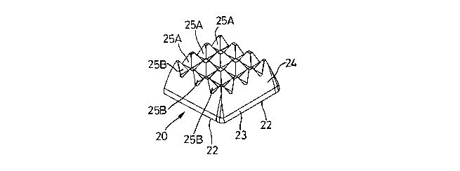
WiVii rEfGreiaGe i.tGiv to F.i.gs. 2 to 4 iI'i part.i.i:uia,r, 41'i2rC is
shown a cutting insert or biade 200 according to the present
invention. ihe insert 2v is cut from a PCD bi.ank having a PCD
phase 23 formed on a carbid.e substrate 24, using an electro
discharge wire c'.z1443..izg process. The 3.PisCr4 210
.i.S a
substantialiy square planar shape having a fiaz front face 21
on the PCD phase with at 'seast two, and prez''erably four
cutting edges 22 formed thereon. The PCD phase generally has
a tiilf''.=iiiless of Q. ri..5-v .7uui depending upon tile size of the
diamond grains. T'ne carbide substrate 24 forms the rear of
CA 02641328 2008-07-31
WO 2007/088353 PCT/GB2007/000323
7
the insert 20 and is typically between 0.55-2.6mm in
thickness. For the present embodiment the PCD phase 23 is
about 0.7mm in thickness and the carbide substrate is between
1.3 & 2.6mm in thickness.
The rear of the insert 20 is provided with at least one
groove 25 in the rear surface, and preferably with a
plurality of serrations 35 thereon. The serrations 25
comprise serrations which extend substantially normal to the
cutting edges 24 for the full length of the blade 16. In the
present example with four cutting edges 34 one set of
serrations 25A extends transversely of the other set of
serrations 25B so that the serrations 25A & 25B intersect
each other forming separate pyramidal projections. The
serrations typically have a depth of 0.85mm and are ground
into the substrate by means of a formed diamond grinding
wheel and are located entirely within the carbide second
phase substrate 24.
With two cutting edges on opposite sides of the blade, the
serrations 25 extend only between said opposite sides.
With reference to Figs. 5 and 6 of the drawings, there is
shown a tool 51 having a shank 52 which in use is clamped
2a into a machine tool for rotation of the tool about its
longitudinal axis.
The tool 51, which is typically a reamer, has a cylindrical
CA 02641328 2008-07-31
WO 2007/088353 PCT/GB2007/000323
8
head 53 which carries at least one cutting insert 20. The
head 53 is typically provided with a plurality of cutting
inserts 20 at angularly spaced locations around the head 13,
and only one of which is shown for the sake of simplicity and
5.the invention will be described in detail with reference to
said one blade only, any other blade being substantially
identical.
Each insert 20 is arranged in a respective recess 54located
in the periphery of the head 53. The head 53 may also have a
plurality of axially extending centering pads (not shown)
spaced around the head. If two inserts 20 are utilised these
may be arranged diametrically opposite each other.
The cutting insert 20 is oriented radially of the head 53.
The recess 54 has a radial side face 56 against which a
cutting insert is,secured by a clamping screw 57.
The serrations 25 on the rear of the insert inter-engage with
like radial serrations 55 on the radial side face 56 of the
recess 54. In this example, the serrations 25 & 55 are in the
form of flat sided straight ribs of triangular cross-section
with the included angle at the apex being between 45-90 of
arc, preferably about 60 of arc. The serrations have a pitch
of between 1.00mm and 1.75mm, and the tops of the ribs are
chamfered. An axially extending clearance hole 58 is provided
at the intersection of the side face 56 of the recess 54, and
the radially inner side of the recess.
CA 02641328 2008-07-31
WO 2007/088353 PCT/GB2007/000323
9
The insert 20 is held in the recess by the screw 57 which
presses the insert 20 so that the serrations 25 & 55 are hard
in abutment with each other, so that any loads on the blade
are transmitted to the tool head 53 through the interengaged
serrations.
The inner facing side of the insert abuts against at least
one adjuster 59. Each adjuster 59 comprises a tapered wedge
which is moveable in a chordal bore 63, by means of an
adjuster screw 64 for radial adjustment of the height of the
cutting edge 22. The total adjustment range will be about
0.5mm.
When an insert is first fitted to a tool, the insert is set
to the correct radial adjustment by the conventional trial
and error technique by adjustment of position of the insert.
The blade is typically set to an accuracy of between 3-5
microns. Thereafter if it is desired to renew the cutting
edge 22, the insert 20 is removed from the notch 22 by
unscrewing of the clamping screw 57. The insert 20 is then
re-positioned to provide a new edge, oi~ replaced- by- a-new
identical blade. Since the serrations 25 on the back face of
any blade are precision ground therein relative to the
cutting edge(s) the new blade when fitted to the reamer will
provide an accurately axially positioned cutting edge and
therefore needs only to be radially adjusted.
The insert 20 may be mounted on a removable carrier (not
CA 02641328 2008-07-31
WO 2007/088353 PCT/GB2007/000323
shown) and the assembled insert 20 and carrier are secured in
the respective recess 54.
Typical machine tools on which the inserts 20 may be used are
5 borers, reamers, milling heads etc.
15
~0