Note: Descriptions are shown in the official language in which they were submitted.
CA 02642058 2008-08-29
WO 2007/082195 PCT/US2007/060260
CARTRIDGE FOR CAULKING COMPOUND,
SEALANT AND/OR ADHESIVES
BACKGROUND
[0001] A dispensing cartridge for caulking compounds, sealants, adhesives and
other similar coating materials typically includes a hollow elongated tubular
container
for confining the material and a tapered nozzle serving as a port for
dispensing
material from the container. The nozzle is fixed to an end cap that is
attached to one
end of the container. A plunger is positioned at an opposite end of the
containerwith
the material disposed between the end cap and the plunger. To dispense
material
from the cartridge, the tip of the nozzle typically is cut off at an angle and
pressure is
applied to the plunger using a conventional caulking gun, or similar
mechanism,
causing the material to flow out of the nozzle to the adjacent surfaces to be
caulked
or sealed.
[0002] In manufacturing, the cartridge is filled with material once the top
end cap
is affixed at one end of the container. Next, the plunger and a ring seal are
inserted
into the container. The ring seal abuts an inner circumferential surface of a
skirt of
the plunger, the skirt being an axially extending annular portion of the
plunger. The
ring seal extends axially beyond a second end of the tubular container, the
second
end being opposite the end where the nozzle and end cap are attached. The ring
seal is deformed, e.g. crimped, around the second end of the container to
retain the
plunger. Upon completion of the manufacturing process the ring seal prevents
movement of the plunger in an axial direction away from the first end while
allowing
the plunger to move towards the top end cap when pressure is applied to the
plunger.
[0003] Attaching the ring seal to the tubular container requires a complex
process
that involves rotating the tubular container. This rotation results in a
vortex being
formed in the material already in the container which results in an air gap in
the
container after the plunger is installed. This air gap is undesirable because
the
entrained air causes material to continue to flow out of the cartridge after
the user of
the caulking gun has tried to stop the flow of material. Also, since the ring
seal
attaches around the lower end of the,tubular container, if the cartridge is
dropped,
then the second end, i.e. the end with the ring seal, deforms along with the
ring seal.
1
CA 02642058 2008-08-29
WO 2007/082195 PCT/US2007/060260
This deformation of the second end of the container inhibits the insertion of
the push
rod of the conventional caulking gun. Furthermore, readjustment of the ring
seal to
allow insertion of the push rod of the caulking gun is quite difficult.
[0004] As opposed to using a ring seal to limit axial movement of the plunger
away from the top end of the tubular container, another method for retaining
the
plunger includes rolling the lower edge of the tubular container over thus
decreasing
the diameter of the lower end of the tubular container. This smaller diameter
portion
limits axial movement of the plunger away from the upper end while allowing
movement of the plunger towards the upper end of the container. By only
rolling
over the lower edge of the container; however, the plunger is not sufficiently
pushed
towards the upper end of the tubular container to protect it from damage that
may
occur if the cartridge is dropped. Furthermore, simply rolling over the lower
edge of
the tubular container does not provide a very secure arrangement for
containing the
plunger. Additionally, by only rolling over the lower edge of the container,
achieving
a coplanar edge on which the plunger can rest is difficult.
SUMMARY OF THE INVENTION
[0005] Accordingly, it is desirable to provide a cartridge for a material that
overcomes the aforementioned problems. One example of such a cartridge
includes
a tubular container, an end plate disposed at a first end to a tubular
container, a
nozzle extending from to the end plate, a plunger received in the tubular
container,
and a barb extending inwardly from the tubular container. The end plate
includes an
opening. The nozzle is in communication with the opening. The barb is
configured
to limit movement of the plunger in a first axial direction.
[0006] Furthermore, it is desirable to provide a method for packaging a
flowable
material that overcomes the difficulties discussed above. Such a method
includes
introducing flowable material into a tubular container, inserting a plunger
into the
container, and deforming the tubular container at a location axially spaced
from an
end of the containerto create a mechanical stop forthe plunger. An end plate
and a
nozzle attach to a first end to the tubular container. The mechanical stop
limits the
movement of the plunger in a first axial direction.
[0007] According to yet another embodiment, a cartridge of material includes a
tubular container, a flowable material disposed in the tubular container, an
end plate
2
CA 02642058 2008-08-29
WO 2007/082195 PCT/US2007/060260
affixed to the a first end of the tubular container, a nozzle affixed to the
end plate, a
plunger disposed in the container, and a mechanical stop formed in the tubular
container. The end plate includes an opening such that the flowable material
can
pass through the opening. The nozzle is in communication with the opening. The
mechanical stop is formed between a second end and the plunger in the tubular
container.
BRIEF DESCRIPTION OF THE DRAWINGS
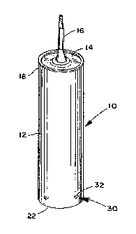
[0008] FIGURE 1 is a perspective view of a cartridge containing a caulking
compound, a sealant, an adhesive, or the like.
[0009] FIGURE 2 is a side cross-sectional view of a lower portion of the
cartridge
of FIGURE 1 showing a portion of a plunger disposed in the cartridge.
[0010] FIGURE 3 is an elevation view, similarto FIGURE 2, of the lower portion
of
the cartridge of FIGURE 1 without showing the plunger.
[0011] FIGURE 4 is a schematic diagram depicting a method of packaging a
material in a cartridge, such as the cartridge depicted in FIGURE 1.
[0012] FIGURE 5 is an elevation view of a cartridge punch assembly for use in
the
manufacturing process of filling the cartridge depicted in FIGURE 1.
[0013] FIGURE 6 is a cross-sectional view of the cartridge punch assembly
depicted in FIGURE 5 taken along line 6-6.
[0014] FIGURE 7 is a cross-sectional view of FIGURE 5 taken along lines 7-7.
DETAILED DESCRIPTION
[0015] With reference to FIGURE 1, a cartridge 10 generally includes a tubular
container 12, an end plate 14, and a nozzle 16. The depicted cartridge is used
to
store and is a package for a flowable material, such as a caulking compound,
an
adhesive, a sealant, or a similar material (simply referred to as "material"
hereafter
for the sake of brevity). Typically the material is a viscous, plastic
flowable
substance that is expelled from the cartridge 10 through the nozzle 16 in a
manner
that will be described in more detail below.
[0016] The tubular container 12 in the depicted embodiment has a circular
configuration in a cross-section taken normal to a longitudinal axis of the
container.
Nevertheless, the tubular container is not limited to only,circular
configurations. For
3
CA 02642058 2008-08-29
WO 2007/082195 PCT/US2007/060260
the ease of understanding the depicted embodiments and not to limit the
invention to
any particular configuration other than that which is claimed, the cartridge
will be
described as including an axial dimension that runs parallel to the
longitudinal axis of
the cartridge and a radial dimension that emanates from the longitudinal axis
and is
perpendicular thereto. The tubular container can be made of cardboard,
plastic, or
similar durable material. The diameter (or area of base) and the height of the
tubular
container is a function of the amount of flowable material that is to be
stored in the
cartridge 10.
[0017] The end plate 14 attaches to and/or is disposed at a first end 18 of
the
tubular container 12. For ease of understanding the drawings only, the first
end 18
will be referred to as the upper end; however, such a term should not be
deemed as
limiting, especially since when in use the first end 18 is typically lower
than a second
end 22 when the cartridge 10 is loaded into a conventional caulking gun and
material
is being expelled or dispensed from the nozzle 16. The end plate 14 is affixed
to the
first end 18 and can be made from any suitable conventional material, such as
metal.
Alternatively, the end plate 14 can be formed integrally, e.g. molded as a
single
piece, with the tubular container 12. Accordingly, the end plate 14 can also
be made
of plastic, or other similar material. The end plate 14 includes a central
opening (not
visible). The nozzle 16 extends axially from the end plate 14 and at least
substantially surrounds the opening in the end plate such that material that
is stored
in the tubular container can exit the cartridge 10 via the nozzle 16. The
nozzle 16
can be cut with a knife or scissors to form an opening through which the
material
flows, and therefore can be made of a plastic material. The tubular container
12, the
end plate 14, and the nozzle 16 are similar to those that are known in the
art.
[0018] The cartridge 10 can be loaded into a cbnventional caulking gun,
similarto
a known cartridge. A push rod of the caulking gun contacts a plunger24 (FIGURE
2)
moving the plunger 24 axially towards the nozzle 16 to dispense material
through the
nozzle. The plunger 24 is similar to the plungers used in conventional
cartridges in
that the plunger is circular and includes an annular skirt 26 that abuts an
inner edge
of the tubular container 12. The plunger 24 can be made of metal or plastic
and has
a complementary shape, which in this embodiment is circular, to the tubular
container 12 that receives the plunger.
4
CA 02642058 2008-08-29
WO 2007/082195 PCT/US2007/060260
[0019] A mechanical stop 30 is provided to limit axial movement of the plunger
24
away from the upper end 18 of the tubular container 12. The mechanical stop 30
inhibits the plunger 24 from backing out of the tubular container 12, for
instance
when the material stored in the cartridge expands, for example when there is
an
increase in temperature.
[0020] In the depicted embodiment, three mechanical stops 30 are provided 120
degrees apart from one another around the circumference adjacent the lower end
22
of the tubular container 12. Where three mechanical stops 30 are provided
these
stops define a plane (three points defining a plane) in which the retained
plunger 24
can reside. Nevertheless, a fewer or greater number of mechanical stops 30 can
be
provided.
[0021] As more clearly seen in FIGURES 2 and 3, each mechanical stop 30 is
axially spaced from the lower end 22 of the tubular container 12. More
specifically,
the lowest portion of each mechanical stop 30 is spaced a predetermined
distance,
e.g. 3/ -1 inches, from the lower end 22 of the container 12. By axially
spacing the
mechanical stops 30 from the lower end 22, deformation of the lower end 22 of
the
tubular container 12, for example where the cartridge 10 is dropped, should
not
damage the mechanical stop 30 in a manner that might result in a plunger 24
backing out of the tubular container 12. Also, the lower end 22 can be easily
bent
back into a generally circular configuration so that the push rod of a
conventional
caulk gun can be received in the lower end 22.
[0022] In the embodiment depicted in FIGURES 1-3, the mechanical stop 30 is
formed using a device, which will be described in more detail below, that
strikes the
tubular container 12 just below the skirt 26 of the plunger 24. It should be
apparent
from the figures, where the cartridge 12 is filled with the first end 18 as a
lower end,
the mechanical stop 30 is formed above the skirt 26 of the plunger 24.
Formation of
the mechanical stop 30 results in an opening 32 being formed in the tubular
container 12 adjacent the lower end 22 of the tubular container. In the
depicted
embodiment, the opening 32 is triangular in configuration and the mechanical
stop
30 has a configuration similar to a burr that includes a first planar wall 34
and a
second planar wall 36 that each include a common linear edge 38. Accordingly,
as
more clearly seen in FIGURE 2, a shelf 42 is provided upon which the plunger
24
can rest. The shelf 42 extends radially inwardly from an inner surface of the
CA 02642058 2008-08-29
WO 2007/082195 PCT/US2007/060260
container 12. Where three or more mechanical stops 30 are provided, the
shelves
42 can define a common plane.
[0023] With reference to FIGURE 4, the method of packaging a flowable material
in the cartridge 10 will be more particularly described. At step 50, material,
e.g.
caulking compound, adhesive, sealant orthe like, is placed into the tubular
container
12 (FIGURE 1) of the cartridge 10 after the end plate 14 and the nozzle 16 has
been
affixed to the tubular container. At step 52, the plunger 24 (FIGURE 2) is
inserted
into the tubular container 12 of the cartridge 10. Steps 50 and 52 are similar
to a
known method for placing a material in a cartridge. As opposed to placing a
ring seal
inside a tubular container, which is done in a known method, oniy the plunger
24
need be inserted into the tubular container. At step 54, the cartridge 10 is
inserted
into a cartridge punch assembly, which will be described in more detail below.
At
step 56, while loaded in the cartridge punch assembly the plunger 24 is
located in the
tubular container 12 and at step 58 the tubular container is punched, or
deformed in
another manner, to create a mechanical stop 30 to retain the plunger 24 from
backing out of the tubular container 12. Such a method does not require
rotation of
the cartridge 10 and/or tubular container 12, thus the air void that was
formed using
the known method having a ring seal is eliminated or greatly reduced.
[0024] As described above, the cartridge 10 (FIGURE 1) is inserted into a
cartridge punch assembly 70 that includes a cartridge alignment head 72, a
plurality
of punch actuating devices 74, a plurality of punch tools 76, and an
adjustable depth
stop 78. As seen in FRGURES 5 and 6, the cartridge 10 is inserted into the
cartridge
punch assembly 70 in a manner that the adjustable depth stop.78 presses
against
the plunger 24 retaining the plunger at a desired location with respect to the
second
end 22 of the tubular container 12. The adjustable depth stop 78 can be
adjusted
from a base surface against which the second end 22 of the tubular container
12
rests to locate the plunger 24 in a desired location. The punch actuating
devices 74,
which in the depicted embodiment are pneumatic cylinders, actuate the punch
tools
76 (three are depicted 120 degrees apart) to strike the cartridge 10 just
above (as
depicted in FIGURE 6) the plunger skirt 26 to form the mechanical stops 30
(FIGURE
1): Each punching tool 76 has a general pyramid shaped configuration that
includes
a point to facilitate a clean punch through the tubular container 12 of the
cartridge 10.
The pyramid shaped punching tool 76 forms a shelf 42 (FIGURE 2) having a
6
CA 02642058 2008-08-29
WO 2007/082195 PCT/US2007/060260
substantially triangular configuration when viewed in a cross-section taken
normal to
the longitudinal axis of the cartridge 10. Alternatively, the punching tool 76
can take
an alternative configuration, which would result in an alternative
configuration forthe
mechanical stop 30. For example, the punching tool 76 can have a rounded
configuration resulting in a mechanical stop having a rounded shelf edge.
[0025] The above-described cartridge provides a robust package for caulking
compounds, adhesives, sealants and the like, that can be inexpensivefy
manufactured and that overcomes the aforementioned difficulties discussed
above.
The depicted cartridge 10 is not as prone to unfixable damage as known
cartridges
that include ring seals or rolled over ends to retain a plunger in a tubular
container.
Also when three mechanical stops are provided, the plunger that is retained
inside
the cartridge resides in a plane that is defined by only three points or
general
locations as opposed to a continuous ring seal or rolled edge that may deviate
from a
single plane.
[0026] Various of the above disclosed and other features and functions, or
alternatives thereof, may be desirably combined into many other different
systems or
applications. Also various presently unforeseen or unanticipated alternatives,
modifications, variations or improvements therein may be subsequently made by
those skilled in the art which are also intended to be encompassed by the
following
claims.
7