Note: Descriptions are shown in the official language in which they were submitted.
CA 02642332 2008-10-29
1
OUTPUT CONTROL APPARATUS OF GENERATOR
BACKGROUND OF THE INVENTION
1. Field of the Invention
The present invention relates to an output control apparatus
of a generator, and particularly to an output control apparatus
of a generator suitable for further improvement of output voltage
waveform by maintaining an electric current f lowing afield winding
constant.
2. Description of the Related Art
In a power generation control apparatus of an
alternating- current(AC)generator which includes a power generation
winding, excitation winding, and field winding, and rectifies
electric current generated in the excitation winding and supplies
the same to the field winding, automatic voltage regulator is known
in the art which maintains a voltage output from the power generation
winding to a predetermined voltage by controlling the electric
current supplied to the excitation winding.
FIG. 6 is a drawing showing composition of primary components
of the AC generator equipped with conventional automatic voltage
regulator. In FIG. 6, a generator 100 includes a field winding 102,
a power generation winding 103, and an excitation winding 104. A
permanent magnet 106 is provided to a rotor 105 around which the
field winding 102 is wound. An automatic voltage regulator (AVR)
107 are provided with a rectifier 108, a voltage detection circuit
109, and a transistor 110. Output of the rectifier 108 is connected
CA 02642332 2008-10-29
2
to the field winding 102 via a brush 111, and a flywheel diode 112
and a capacitor 113 are connected in parallel with the field winding
102. The excitation winding 104 is connected to input side of the
rectifier 108. The rotor 105 is driven by a driving source such
as engine (not shown).
In FIG. 6, when the rotor 105 is driven by the engine or the
like, an electric current is generated to the excitation winding
104 by the permanent magnet 106. This electric current is rectified
by the rectifier 108 and is supplied to the field winding 102 in
the form of direct-current (DC) excitation current. The voltage
detection circuit 109 compares an output voltage of the power
generation winding 103 with a predetermined voltage and executes
ON/OFF control of the transistor 110 depending on magnitude of the
output voltage with regard to the reference voltage. When the
transistor 110 isON, electric current flows through the field winding
102 thereby increasing output of the power generation winding 103,
and when the transistor 110 is OFF, electric current does not flow
through the field winding 102 and output of the power generation
winding 103 is decreased. Output of the generator 100 is maintained
constant by ON/OFF control of the transistor. An example of such
AC generator equipped with the automatic voltage generator is
described in Japanese Patent Application Laid-Open (JP-A) No.
08-140400.
In the above-mentioned generator, by flowing an electric
current through thefield ieldwinding 102, an indcurrent is generated
to the power generation winding 103, then a back electromotive force
CA 02642332 2008-10-29
3
is induced to the field winding 102 by magnetic field generated
by the electric current. Since the electric current flowing through
the field winding 102 is increased or decreased by the back
electromotive force, output of the power generation winding 103
fluctuates. However, with conventionalautomatic voltage regulator
107 which is based on the principle that current increase in constant
direction is stopped by the transistor 110, electric current f lowing
through the flywheel diode 112 connected in parallel with the field
winding 102 can not be decreased. When field current is PWM
controlled based on voltage detection in the voltage detection
circuit 109, the flywheel diode 112 is indispensable to absorption
of surge voltage generated at energizing stop and smoothing of the
field current.
Theref ore, with the control apparatus having the f lywheel diode
112, it is not easy to maintain the electric current flowing through
the field winding 102 constant. When the electric current flowing
through the field winding 102 can not be maintained constant, output
voltage of the power generation winding 103 has distortions with
respect to the sinusoidal wave. Hence, further improvement of the
output voltage waveform is desired.
SUMMARY OF THE INVENTION
The present invention has been made in light of the
above-mentioned needs and an object of the present invention is
to provide an output control apparatus of a generator equipped with
an automatic voltage regulator capable of improving output waveform
CA 02642332 2008-10-29
4
of the AC generator.
A first feature of the present invention is such that, in an
output control apparatus of a generator including a power generation
winding being wound around stator side and an excitation winding,
a f ield winding being wound around a rotor turned by a driving source,
and a rectifier which rectifies electric current generated by the
excitation winding and supplies the same to the field winding, which
apparatus includes an electric current detectionmeans for detecting
a field current flowing the field winding and an impedance adjustment
means being disposed in series to the field winding, wherein the
impedance adjustment means is composed so as to adjust the impedance
of a circuit including the field winding so that a field current
detected by the electric current detection means converges with
a predetermined target electric current.
A second feature of the present invention is such that, the
target electric current is decreased when output voltage of the
power generation winding is greater than a reference voltage and
is increased when the output voltage is smaller than the reference
voltage.
A third feature of the present invention is such that, the
impedance adjustment means includes a transistor connected to the
circuit including thefield winding, and a comparator which outputs
a voltage depending on a difference between the f ield current detected
by the electric current detection means and the target electric
current, wherein the impedance is adjusted by inputting an output
of the comparator to a base of the transistor to increase or decrease
CA 02642332 2008-10-29
an emitter-collector resistance of the transistor.
A fourth feature of the present invention is such that, the
impedance adjustment means is provided to the circuit including
the field winding and includes a plurality of lines each having
5 different resistance value, and wherein the impedance is adjusted
by selecting any of the plurality of lines according to the output
voltage of the power generation winding to increase or decrease
resistance of the circuit including the field winding.
According to the present invention having the first through
fourth features, since field current flowing through the field
winding can be detected by the electric current detection means,
a variation in the field current due to mutual interaction of the
field winding and the power generation winding can be detected
directly. Further, the f ield currentbeing detected can be converged
with an appropriate target electric current by impedance adjustment
of the circuit includingthe fieldwindingbythe impedance adjustment
means. Accordingly, different from conventional technology in
which the field current is turned ON/OFF by a switching element,
the flywheel diode for surge voltage absorption generated at
energizing stop is unnecessary. As a result, influences of the
electric current flowing through the flywheel diode are removed,
variation inthe field current can be reflected accurately to controls,
and therefore, the field current can be stabilized and output of
the generator winding, i.e., waveform of the generator output, can
be improved.
CA 02642332 2008-10-29
6
BRIEF DESCRIPTION OF THE DRAWINGS
FIG. 1 is a drawing showing composition of primary components
of the generator including output control apparatus relating to
one embodiment of the present invention.
FIG. 2 is a circuit diagram showing specific example of the
impedance adjustment circuit.
FIG. 3 is a circuit diagram showing modification of the
impedance adjustment circuit.
FIG. 4 is a block diagram showing functions of the primary
components of a line selection unit of the impedance adjustment
circuit.
FIG. SA is a drawing showing output voltage waveform of the
generator controlled by the automatic voltage control apparatus
of prior art.
FIG. 5B is a drawing showing results of improvement of output
voltage waveform ofthe generator controlled by the automatic voltage
control apparatus of the embodiment as compared to those of prior
art.
FIG. 6 is a drawing showing composition of primary components
of the AC generator having conventional automatic voltage regulator.
DETAILED DESCRIPTION OF THE PREFERRED EMBODIMENT
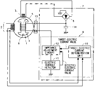
Referring now to the drawings, the present invention will be
explained in detail hereafter. FIG. 1 is a drawing showing
composition of primary components of the generator including output
control apparatus relating to one embodiment of the present invention.
CA 02642332 2008-10-29
7
A generator 1 is an AC generator well known to the art and includes
a power generation winding 2 and an excitation winding 3 provided
at stator side, and a field winding 5 being wound around a rotor
4. A permanent magnet 6 is mounted to the rotor 4 for generation
of excitation current on the excitation winding 3. The rotor 4 is
driven by a driving source such as engine (not shown).
An automatic voltage regulator 7 includes a rectifier 8 and
an electric current control unit 9. Both ends of the excitation
winding 3 are connected to input side of the rectifier 8. The electric
current control unit 9 includes a target electric current
determination unit 10, an electric current detector 11, and an
impedance adjustment circuit 12. One end of the field winding 5
is connected to output side of the rectifier 8 and the other end
of the field winding 5 is connected to the impedance adjustment
circuit 12. The field winding5 and the automatic voltage regulator
7 are connected via a brush 13. A capacitor 14 for smoothing the
output voltage of the rectifier 8 is provided between the rectifier
8 and the ground.
Operations of the automatic voltage regulator 7 shown in FIG.
1 will be explained. When the rotor 4 is turned by such as the engine,
an electric current is induced to the excitation winding 3 by magnetic
field of the permanent magnet 6. This electric current is rectified
by the rectifier 8 and is supplied to the field winding 5 as DC
excitation current. A voltage generated in the power generation
winding 2, i.e., output voltage of the generator 1, is determined
depending onthe electric current flowing through the field winding 5.
CA 02642332 2008-10-29
Hence, in the present embodiment, in order to maintain the output
voltage of the power generation winding 2 at a predetermined voltage,
the electric current flowing through the field winding 5 is designed
to be controlled depending on a deviation between output voltage
and reference voltage of the power generation winding 2.
The target electric current determination unit 10 compares
output voltage value input from the power generation winding 2
(voltage value representative of output voltage value) with the
reference voltage and detects a deviation between these two voltages.
The target electric current determination unit 10 then outputs a
target electric current value being set preliminary depending on
the deviation. The target electric current value is input to the
impedance adjustment circuit 12.
The electric current detector 11 detects a value of the electric
current flowing through the field winding 5 and inputs it into the
impedance adjustment circuit 12. The impedance adjustment circuit
12 compares the detected electric current value being input from
the electric current detector 11 with the target electric current
value being input from the target electric current determination
unit 10 and adjusts the impedance of the field winding 5 so that
the detected electric current value converges with the target
electric current value.
Since all electric currents f lowing through thefield winding
5 go through the impedance adjustment circuit 12, electric currents
flowing through the field winding 5 can be controlled freely by
increasing or decreasing the impedance by the impedance adjustment
CA 02642332 2008-10-29
9
circuit 12. Therefore, the output voltage of the power generation
winding2can be held constant while electric currents flowingthrough
the field winding 5 are controlled.
A specific example of the impedance adjustment circuit 12 is
shown in FIG. 2. The impedance adjustment circuit 12 includes a
transistor 15 provided in the field current path and a comparator
16 which connects a voltage as the comparison result to the base
of the transistor 15. A shunt resistor 17 provided between the
transistor 15 and the ground is the electric current detector 11.
A voltage value representative of the target electric current Iref
being input from the target electric current determination unit
10 is input to positive side input terminal of the comparator 16.
Avoltage value representative of the field current If being detected
by the shunt resistor 17 is input to negative side input terminal
of the comparator 16. The comparator 16 inputs a voltage
corresponding to deviation of the field current If with regard to
the target electric current value Iref to the base of the transistor
15. Electric current flowing across collector and emitter of the
transistor 15 is controlled to a value corresponding to the voltage
to be applied to the base of the transistor 15. In other words,
when the field electric current If detected by the shunt resistor
17 is greater than the target electric current value Iref , the voltage
to be applied to the base of the transistor 15 is decreased. In
contrast, when the field electric current If is smaller than the
target electric current value Iref, the voltage to be applied to
the base of the transistor 15 is increased.
CA 02642332 2008-10-29
= 10
A microcomputer may be used in lieu of the comparator 16. For
example, a detected electric current is input to the microcomputer,
and a voltage value corresponding to the detected electric current
is calculated in the microcomputer using a predetermined function.
Results of the calculationare converted fromdigital data to analogue
signal, and are input to the base of the transistor 14.
Although impedance is adjusted continuously in the impedance
adjustment circuit 12 shown above, stepwise impedance adjustment
may be employed. FIG. 3 is a circuit diagram showing modification
of the electric current control unit 9 which adjusts the impedance
in stepwise fashion. In FIG. 3, the impedance adjustment circuit
12 includes eight parallel lines provided in the field current path,
eight resistors Rl, R2, ... R8 provided to each of eight lines, and
transistors 18-1, 18-2, ... 18-8 connected in series to each of
resistances. Each of resistances Rl to R8 has different resistance
value. Lines having these resistances and transistors are not
limited to eight lines.
A line selection unit 19 is a means for selecting any one of
transistors 18-1 to 18-8 and has function for comparison of output
voltage of the power generation winding 2 with the reference voltage.
The line selection unit 19 calculates a target electric current
value based on a deviation of the output voltage of the power
generation winding 2 with regard to the reference voltage and outputs
a selection signal to, of eight lines, the line set preliminary
corresponding to the deviation in order to put the field current
closer to the target electric current value. One of transistors
CA 02642332 2008-10-29
11
18-1 to 18-8, to which the selection signal is being input to the
base thereof is turned ON, and the field current If flows through
the resistance to which this transistor is connected. Since each
of resistors R1 to RB has different resistance value, the field
current If is changed by the transistor to which the selection signal
is input.
FIG. 4 is a block diagram showing functions of the primary
components of the line selection unit 19. This function can be
composed of the microcomputer. Output voltage Vout of the power
generation winding 2 is input to a target electric current
determination unit 20 and a target electric current value Itgt
corresponding to deviation of the output voltage Vout with regard
to the reference voltage Vref is determined. An electric current
comparison unit 21 calculates a deviation (electric current
deviation) DI of f ield current If being detected by a voltage-current
detector 11 with regard to the target electric current value Itgt
and inputs calculation result to a change-over unit 22. The
change-overunit 22 selects port P1 to P8 corresponding to the electric
current deviation DI being input and outputs a change-over signal.
That is, the port selected is activated. Each of the ports Pl to
P8 is connected to transistors 18-1 to 18-8 and the transistor
connected to the activated port is turned ON.
FIG. 5A and FIG. 5B show results of improvement of output voltage
waveformof the generator 1 by the automatic voltage control apparatus
according to the present embodiment as compared to those by
conventional technology. FIG. 5A shows output voltage waveform
CA 02642332 2008-10-29
12
(upper one) of the power generation winding and electric current
waveform (lower one) of the field wiring relating to the conventional
technology. FIG. 5B shows output voltage waveform (upper one) of
the power generation winding 2 and electric current waveform (lower
one) of the field winding 5 relating to the present embodiment.
As shown in FIG. 5A, according to the conventional technology,
since field current waveform fluctuates significantly, sinusoidal
wave of the output voltage waveform of the power generation winding
includes distortions. In the meantime, in the generator 1 relating
to the present embodiment, as noticed with field current waveform
shown in FIG. 5B, impedance of the field current path including
the field winding 5 is adjusted by the automatic voltage regulator
and the field current is stabilized. Therefore, a clear sinusoidal
wave with less distortion is obtained as the output voltage waveform
of the generator winding 2.