Language selection

Search

Patent 2642865 Summary

Third-party information liability

Some of the information on this Web page has been provided by external sources. The Government of Canada is not responsible for the accuracy, reliability or currency of the information supplied by external sources. Users wishing to rely upon this information should consult directly with the source of the information. Content provided by external sources is not subject to official languages, privacy and accessibility requirements.

Claims and Abstract availability

Any discrepancies in the text and image of the Claims and Abstract are due to differing posting times. Text of the Claims and Abstract are posted:

  • At the time the application is open to public inspection;
  • At the time of issue of the patent (grant).
(12) Patent: (11) CA 2642865
(54) English Title: MEANS FOR DELIVERY OF FLOWABLE MEDIA, ESPECIALLY LUBRICANTS
(54) French Title: DISPOSITIF DE CIRCULATION DE FLUIDES A CAPACITE D'ECOULEMENT, EN PARTICULIER DES LUBRIFIANTS
Status: Expired and beyond the Period of Reversal
Bibliographic Data
(51) International Patent Classification (IPC):
  • F4B 53/08 (2006.01)
  • F4D 29/58 (2006.01)
(72) Inventors :
  • LEHMANN, FRANK GUENTER (Germany)
(73) Owners :
  • HYDAC SYSTEM GMBH
(71) Applicants :
  • HYDAC SYSTEM GMBH (Germany)
(74) Agent: MARKS & CLERK
(74) Associate agent:
(45) Issued: 2013-10-01
(86) PCT Filing Date: 2006-12-20
(87) Open to Public Inspection: 2007-10-25
Examination requested: 2010-12-03
Availability of licence: N/A
Dedicated to the Public: N/A
(25) Language of filing: English

Patent Cooperation Treaty (PCT): Yes
(86) PCT Filing Number: PCT/EP2006/012270
(87) International Publication Number: EP2006012270
(85) National Entry: 2008-08-19

(30) Application Priority Data:
Application No. Country/Territory Date
10 2006 015 602.1 (Germany) 2006-04-04

Abstracts

English Abstract

A device for conveying flowable materials, in particular lubricants, with a motor-driven pump (1) forming a component of a piping system, is characterized in that at least one heating element (21)that can be activated by feeding power to it, is provided outside the housing (3) of the pump (1) in a position enabling heat transmission to the housing (3).


French Abstract

Un dispositif pour faire circuler des fluides à capacité d'écoulement, en particulier des lubrifiants, avec une pompe (1) formant une partie constituante d'un système de canalisations et fonctionnant avec un moteur, se caractérise en ce que au moins un élément chauffant (21) pouvant être activé par alimentation d'énergie est disposé en dehors du boîtier (3) de la pompe (1) dans une position permettant une transmission de chaleur au boîtier (3).

Claims

Note: Claims are shown in the official language in which they were submitted.

7
The embodiments of the invention in which an exclusive property or
privilege is claimed are defined as follows:
1. A device for delivering flowable media, comprising:
a pump driven by a motor, forming a component of a line system and having
a pump housing with opposite first and second end walls joined by first and
second
side walls;
a fluid input and a fluid output aligned on said first and second end walls,
respectively, and defining a start position and an end position of an inner
flow path
of said pump;
displacement elements of said pump in said pump housing;
at least one heating element activated by an energy supply located outside of
said pump housing in a position to transfer heat to said pump housing, said
heating
element unit including a first PTC heating element on a flat section of an
outside
surface of said first side wall at a height of said fluid input and said fluid
output;
a second PTC heating element attached on a flat section of an outside surface
of said second side wall of said pump housing, said flat sections being
adjacent said
displacement elements in said pump housing; and
a carrier formed of an aluminum sheet mounting said first and second PTC
heating elements to said flat sections of said outside surfaces of said pump
housing
to transfer heat to said pump housing, said PTC heating elements having flat
outer
sides adjoining said carrier.
2. A device according to claim 1, wherein:
said carrier is U-shaped with parallel U-legs and forms a collar extending
about said flat sections of said outside surfaces of said pump housing, each
of said
U-legs supporting one of said PTC heating elements.
3. A device according to claim 2, wherein:
said U-legs are connected by a crosspiece enclosing a bottom part of said
pump housing; and
an electrical connector is on an outside surface of said crosspiece to supply
electrical power to said PTC heating elements.

8
4. A device according to claim 3, wherein:
enclosures hold said PTC heating elements in contact with said U-legs, are
attached to outside surfaces of said U-legs, and are formed of highly heat-
conductive metallic material.
5. A device according to claim 4, wherein:
said PTC heating elements adjoin said U-legs over a large area thereof.
6. A device according to any one of claims 1 to 5, wherein:
said pump includes a pump shaft; and
a heat-insulating jacket surrounds said pump housing and said heating
elements while leaving exposed said pump shaft, said fluid input and said
fluid
output.
7. A device for delivering flowable media, comprising:
a pump driven by a motor, forming a component of a line system and having
a pump housing with opposite first and second end walls joined by first and
second
side walls, said side walls having outside surface sections;
a fluid input and a fluid output aligned on said first and second end walls,
respectively, defining a start position and an end position of inner flow path
of said
pump;
displacement elements of said pump in said pump housing between said fluid
input and fluid output, said outside surface sections being adjacent said
displacement elements in said pump housing;
a carrier formed of an aluminum sheet and placed on said outside surface
sections; and
first and second PTC heating elements having flat surfaces mounted on said
carrier and activated by electrical energy supplied from outside said pump
housing
to transfer heat to said pump housing.
8. A device according to claim 7, wherein:

9
said carrier is U-shaped with parallel U-legs, and forms a collar extending
about said outside surface sections of each of said U-legs supporting one of
said
PTC heating elements.
9. A device according to claim 8, wherein:
said U-legs are connected by a crosspiece enclosing a bottom part of said
pump housing; and
an electrical connector is on an outside surface of said crosspiece to supply
electrical power to said PTC heating elements.
10. A device according to claim 9, wherein:
enclosures hold said PTC heating elements in contact with said U-legs, are
attached to outside surfaces of said U-legs, and are formed of highly heat-
conductive metallic material.
11. A device according to claim 9, wherein:
said PTC heating elements adjoin said U-legs over a large area thereof.
12. A device according to any one of claims 7 to 11, wherein:
said pump includes a pump shaft; and
a heat-insulating jacket surrounds said pump housing and said PTC heating
elements while leaving exposed said pump shaft, said fluid input and said
fluid
output.

Description

Note: Descriptions are shown in the official language in which they were submitted.


CA 02642865 2011-08-31
Means for Delivery of Flowable Media, Especially Lubricants
The invention relates to a means for delivery of flowable media, especially of
lubricants,
with a pump which can be driven by a motor and which forms a component of a
line system.
In known means of this type, under certain unfavorable operating conditions
there is the
danger that malfunctions, for example a drop of delivery output, pump
overload, or even its failure
will occur. These difficulties can occur especially when overly low oil
temperatures occur as
lubricating oils are being delivered in a lubricant circuit. These operating
states prevail for example
during cold running phases of certain systems or occur in wind power plants
under winter
conditions, and these states can last over longer time intervals. The
corresponding strong increase of
the viscosity of the lubricating oils to be delivered leads at least to a
reduction of the delivery output,
resulting in danger to the assigned machinery system, or in less favorable
cases leads to overloading
or even failure of the pump; this in turn entails corresponding subsequent
damage to the pertinent
system.
With respect to this prior art, an object of the invention is to make
available a means for
delivering flowable media, especially lubricants, with operating reliability
which is ensured even
when very low temperatures of the line system and the medium to be delivered
prevail.

CA 02642865 2011-08-31
2
According to an aspect of the invention heat transfer to the pump housing is
provided from the outside. In this way, on the one hand the result is that if
necessary a
direct temperature increase can take place in the critical, i.e. fault-
susceptible area of
the line system, specifically directly on the pump. On the other hand, the
heating
of the pump housing leads to a corresponding temperature increase of the
delivered medium; this
causes a corresponding temperature increase of the entire pertinent line
system, including an
increase of a possible overly low oil temperature in a lubricant circuit.
In especially advantageous exemplary embodiments there is at least one heating
element in
=the form of a self-regulating electrical resistance element with a positive
temperature coefficient (PTC), for
example in the form of a so-called PTC heating element. Commercially available
PTC heating
elements consist of doped polycrystalline ceramic with barium titanate as the
base material. These
PTC elements ensure rapid heat-up, have good self- regulation behavior and
thus a long service life,
since there is no danger of overheating due to the self-regulating properties.
The use of such PTC
elements is therefore also especially advantageous because these elements can
automatically
maintain a desired temperature level, without control means or temperature
sensors being necessary.
Preferably the housing of the pump has more than one flat outside wall
section, to each of
which one PTC element is assigned.
Preferably the arrangement here is made such that the PTC heating elements are
assigned to
those outside wall sections of the housing which are spatially adjacent to the
inside displacement
elements of the pump. This piston arrangement leads to especially effective
and prompt heat-up in
the desired region which is critical against insufficient temperatures.

CA 02642865 2011-08-31
3
In exemplary embodiments in which on the pump housing the fluid input and
output which
define the start and end of the inner pump flow path which has the
displacement elements are placed
flush with one another on one end wall or rear wall of the pump housing,
preferably on the side
walls which join the end wall and the rear wall to one another, there is one
PTC heating element
each in this outside wall section which is placed at the height of the fluid
input and output. This
yields especially specific heat-up in the area of the inner flow path of the
pump.
In advantageous exemplary embodiments, the carrier for the PTC heating
elements is an
aluminum sheet which adjoins the pertinent outside wall sections for heat
transfer, and adjoining the
outer side of which are the PTC heating elements made in a flat construction.
This support of the
PTC heating elements ensures especially good heat transfer to the pump
housing.
In this connection the carrier can be made U-shaped and with IJ-legs which run
parallel to
one another it can form one collar of the two opposing outside wall sections
of the pump housing at
a time, on the outside of each U leg there being one PTC heating element.
The PTC heating elements for their part can be held in contact with the U-legs
by means of
an enclosure which can be attached to the outside of the U-legs and which is
made from highly heat-
conductive metallic material.
The efficiency of the means is especially good when the pump housing is
surrounded with
heat-insulating jacketing, leaving its pump shaft and fluid input and output
exposed, so that heat
losses to the vicinity are for the most part prevented. This jacketing with
which the housing is for
example cast round, prevents not only heat exit to the outside, but also forms
protective jacketing
which prevents direct access to the PTC heating elements.
According to an aspect of the present invention there is provided a device for
delivery of flowable media, the device comprising:
a pump which can be driven by a motor and which forms a component of a line
system, said pump having a pump housing; and
at least one heating element, which can be activated by an energy supply,
wherein the at least one heating element is located outside of the pump
housing in
a position which enables heat transfer to the pump housing.

CA 02642865 2011-08-31
3a
The invention is explained below in detail with reference to an exemplary
embodiment shown in the drawings, in which

CA 02642865 2008-08-19
4
- FIG. 1 shows a perspective oblique view of a pump intended for one
exemplary
embodiment of the invention;
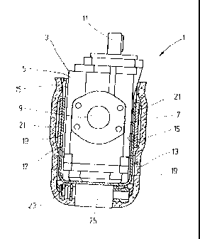
- FIG. 2 shows a front view, looking at the end wall of the pump housing,
its components
surrounding the side walls being shown cutaway;
- FIG. 3 shows a perspective oblique view of part of a carrier which forms
the collar of the
side walls of the pump housing with PTC heating elements located on its
outside and their
electrical connecting means;
- FIGS. 4 and 5 shows a side view and a front view of the support from FIG.
3;
- FIG. 6 shows a bottom view drawn roughly in actual size of a metallic
enclosure of a PTC
heating element of flat construction held in it and
FIG. 7 shows a section according to line V1I-VII from FIG. 6.
FIGS. 1 and 2 show a pump labelled 1 overall, with a pump housing 3 which has
a fluid
input 9 provided with a connecting flange 7 on the front end wall.
Diametrically opposite on the rear
wall which is not shown in the figures there is a corresponding fluid output
which is flush with the
fluid input 9. Within the flow path of the pump 1 between the fluid input 9
and fluid output there is
a gear pair which forms the displacement elements, i.e. the pump 1 is an
outside gear pump with a
drive shaft 11 which is located on the top of the housing. As is best shown in
FIG. 1, the pump
housing 3 is surrounded with heat-insulating jacketing 13, leaving exposed the
areas of the fluid
input 9, of the housing top with the drive shaft 11, and of the area of the
fluid output which is not
shown. In this connection it can be a cast or foamed jacket.

CA 02642865 2008-08-19
FIG. 2 shows the part of the jacket 13 which includes the side walls 15 of the
pump housing
3 which extend between the end wall 5 and the rear wall, in a vertically cut
representation, its being
apparent that between the side walls 15 and the jacketing 13 there is a U-
shaped carrier.
FIGS. 3 to 5 show the carrier 17 in greater detail. The carrier 17 which has
been shaped
from aluminum sheet has two U-legs 19 which are intended to make contact with
the side walls 15
of the pump housing 3 and which define planes which are parallel to one
another. A PTC element
unit 21 which is shown only schematically in FIGS. 3 to 5 is attached to the
outside of each U-leg
19. FIGS. 6 and 7 show details of the PTC element units 21. Each of the
element units 21 is
provided with its own PTC element 29 in the form of a flat cuboid. The latter
is located in an
enclosure 31 which is made in the manner of a round disk of metal with good
heat conductivity,
provided with profiling. The enclosure 31 has central profiling 33 which on
the bottom 35 of the
enclosure 31 which is intended for contact with the pertinent U-leg 19 forms a
receiving channel 37
in which the PTC element 29 is fixed by a heat-resistant adhesive film strip
39, in the exemplary
embodiment a Kapton strip. On either side of the receiving channel 37 there
are profilings 41 of
low height with a round mounting hole 43 and an oblong hole 45 for forming a
screw connection
between the enclosure 31 and the pertinent U leg 19.
Connecting wires 27 intended for power supply of the PTC element 29 are
connected in the
manner conventional for PTC elements 29 to the flat metal electrodes provided
thereon. In the end
area bordering the PTC element 29 the connecting wires 27 are surrounded by a
silicone insulating
tube 47. Moreover the transition area between the end of the connecting wires
27 provided with the
insulating tube 47 can be sealed with rubber in the area bordering the PTC
element 29.
The enclosure 31 attached to the pertinent U-leg 19 of the carrier 17 forms a
heat conducting
plate for transfer of the heat generated by the PTC element 29 to the aluminum
sheet of the pertinent
U-leg 19 which for its part adjoins the pertinent side wall 15 of the pump
housing 3 as a heat
transfer agent. This thermal coupling makes it possible using the self-
regulating characteristic of the

CA 02642865 2008-08-19
6
PTC heating element 29 to maintain the desired temperature during changing
operating states on the
pump housing 3 without the need for control electronics for this purpose.
The invention is explained above using the example of an outside gear pump. It
goes
without saying that the invention can be used likewise in pumps of a different
design, for example
for inside gear pumps, screw pumps, vane cell pumps, radial piston pumps or in
pumps with a
different operating principle. In any case it is advantageous to attach the
pertinent PTC heating
elements to the respective pump housing in a position such that there is good
thermal coupling to
the pertinent inner displacement elements. While the invention is explained
using one example in
which two element units 21 with one contained PTC element 29 each are used, it
goes without
saying that there could be a different number of PTC elements 29 and that
other designs different
from the flat execution can be used, for example PTC elements with a round or
rectangular cartridge
shape.

Representative Drawing
A single figure which represents the drawing illustrating the invention.
Administrative Status

2024-08-01:As part of the Next Generation Patents (NGP) transition, the Canadian Patents Database (CPD) now contains a more detailed Event History, which replicates the Event Log of our new back-office solution.

Please note that "Inactive:" events refers to events no longer in use in our new back-office solution.

For a clearer understanding of the status of the application/patent presented on this page, the site Disclaimer , as well as the definitions for Patent , Event History , Maintenance Fee  and Payment History  should be consulted.

Event History

Description Date
Time Limit for Reversal Expired 2017-12-20
Letter Sent 2016-12-20
Grant by Issuance 2013-10-01
Inactive: Cover page published 2013-09-30
Inactive: Final fee received 2013-07-08
Pre-grant 2013-07-08
Notice of Allowance is Issued 2013-03-20
Letter Sent 2013-03-20
4 2013-03-20
Notice of Allowance is Issued 2013-03-20
Inactive: Approved for allowance (AFA) 2013-03-12
Amendment Received - Voluntary Amendment 2012-09-26
Inactive: S.30(2) Rules - Examiner requisition 2012-04-03
Amendment Received - Voluntary Amendment 2011-08-31
Letter Sent 2010-12-09
Request for Examination Requirements Determined Compliant 2010-12-03
All Requirements for Examination Determined Compliant 2010-12-03
Request for Examination Received 2010-12-03
Letter Sent 2009-04-22
Inactive: Single transfer 2009-02-23
Amendment Received - Voluntary Amendment 2008-12-23
Inactive: Cover page published 2008-12-11
Inactive: Declaration of entitlement/transfer - PCT 2008-12-09
Inactive: Notice - National entry - No RFE 2008-12-09
Inactive: First IPC assigned 2008-12-04
Application Received - PCT 2008-12-03
National Entry Requirements Determined Compliant 2008-08-19
Application Published (Open to Public Inspection) 2007-10-25

Abandonment History

There is no abandonment history.

Maintenance Fee

The last payment was received on 2012-10-25

Note : If the full payment has not been received on or before the date indicated, a further fee may be required which may be one of the following

  • the reinstatement fee;
  • the late payment fee; or
  • additional fee to reverse deemed expiry.

Patent fees are adjusted on the 1st of January every year. The amounts above are the current amounts if received by December 31 of the current year.
Please refer to the CIPO Patent Fees web page to see all current fee amounts.

Owners on Record

Note: Records showing the ownership history in alphabetical order.

Current Owners on Record
HYDAC SYSTEM GMBH
Past Owners on Record
FRANK GUENTER LEHMANN
Past Owners that do not appear in the "Owners on Record" listing will appear in other documentation within the application.
Documents

To view selected files, please enter reCAPTCHA code :


To view images, click a link in the Document Description column (Temporarily unavailable). To download the documents, select one or more checkboxes in the first column and then click the "Download Selected in PDF format (Zip Archive)" or the "Download Selected as Single PDF" button.

List of published and non-published patent-specific documents on the CPD .

If you have any difficulty accessing content, you can call the Client Service Centre at 1-866-997-1936 or send them an e-mail at CIPO Client Service Centre.


Document
Description 
Date
(yyyy-mm-dd) 
Number of pages   Size of Image (KB) 
Description 2008-08-18 6 234
Drawings 2008-08-18 3 50
Abstract 2008-08-18 1 10
Representative drawing 2008-08-18 1 12
Claims 2008-08-18 2 69
Cover Page 2008-12-10 1 38
Description 2011-08-30 7 244
Claims 2011-08-30 2 84
Claims 2012-09-25 3 101
Representative drawing 2013-09-05 1 11
Cover Page 2013-09-05 1 39
Notice of National Entry 2008-12-08 1 194
Courtesy - Certificate of registration (related document(s)) 2009-04-21 1 103
Acknowledgement of Request for Examination 2010-12-08 1 176
Commissioner's Notice - Application Found Allowable 2013-03-19 1 163
Maintenance Fee Notice 2017-01-30 1 178
PCT 2008-08-18 4 153
Correspondence 2008-12-08 1 24
Correspondence 2013-07-07 1 32