Note: Descriptions are shown in the official language in which they were submitted.
CA 02642885 2008-08-13
WO 2007/095563 PCT/US2007/062109
ELECTRIC REACTION TECHNOLOGY FOR FUELS PROCESSING
[0001] This application is based on, and claims priority to, provisional
application having
serial number 60/773,613, having a filing date of February 15, 2006, entitled
Electric Reaction
Technology for Pollution-Free Fuels Decarbonization and utility application
having serial
number 11/674,250, having a filing date of February 13, 2007, entitled
Electric Reaction
Technology for Fuels Processing.
BACKGROUND OF THE INVENTION
[0002] Carbon dioxide is produced when burning any hydrocarbon fuel.
Additional carbon
dioxide is produced by the chemical industry when hydrocarbons are used as
feedstocks for
catalytic steam reforming, partial oxidation and water gas shift reaction
processes to manufacture
hydrogen-containing synthesis gas. Little has changed in the last 50 years and
almost all this
carbon dioxide finds its way into the atmosphere. In recent years, carbon
dioxide has been
identified as a contributor to global climate change. Governments and
corporations have
proposed many methods to reduce or manage atmospheric carbon dioxide
emissions.
Furthermore, major efforts have been mounted to produce hydrogen more
economically, since it
burns cleanly, producing only water (as steam) and heat as combustion
products. All approaches
to move toward environmentally friendly fuels entail great complexity and
expense.
[0003] The only way to completely eliminate the production of carbon dioxide
when combusting
hydrocarbons would be to:
1. Apply heat to hydrocarbons to cause decomposition to elemental carbon
and molecular hydrogen;
2. Separate the hydrogen and carbon; and
3. Either burn the hydrogen with air or oxygen forming high temperature
steam as a useful source of heat or electrochemically convert the hydrogen
into water and electricity in a fuel cell.
[0004] In such processes, the heating value of carbon combustion would be
unrealized as useful
heat. This loss of carbon heating value would nominally require twice the fuel
to produce a
given amount of hydrogen or process heat. However, carbon solids recovered in
the process
CA 02642885 2012-05-18
could be marketed or stored (sequestered) much more economically than by 'end-
of-the-process'
capture and sequestration of carbon dioxide.
[0005) Accordingly, a need exists for a method and apparatus to produce
hydrogen in an efficient
manner with limited carbon dioxide emission.
SUMMARY OF THE INVENTION
10006] Embodiments of the invention provide a method and apparatus for
producing hydrogen
wherein a hydrocarbon gas is fed into an electric reaction technology system
to decompose the
hydrocarbon gas to hydrogen gas and carbon solids. The electric reaction
technology system
comprises one or more heating zones, wherein each heating zone comprises one
or more heating
stations and each heating station comprises one or more heating screens. (The
term "screen" as
used herein means a meshed wire component.) Preferably, a final near-
equilibrium attainment
zone without additional heat input follows either the complete ERT heating
phase or one or more
stages of the ERT heating phase. In an illustrative embodiment of the
invention, the attainment
zone comprises a carbon reaction chamber. Preferably, the temperature of the
hydrogen and any
remaining carbon and hydrocarbons leaving the electric reaction technology
system is in the range
of about 2000 F to about 2700 F. After passing the hydrogen gas through the
electric reaction
technology system, the hydrogen gas and any remaining carbon solids and
hydrocarbon gas are
cooled. The hydrogen gas and any remaining carbon solids and hydrocarbon gas
then flow
through a phase separation system, such as a scrubber, filtration or drying
system for example, to
remove substantially all of the carbon, leaving hydrogen product.
[0007] In an illustrative embodiment of the invention, heat generated from the
electric reaction
technology system is used to heat the incoming hydrocarbon gas feed.
Preferably, the
hydrocarbon gas feed is heated by the heat generated from the electric
reaction technology
system to a temperature in the range of about 400 F to about 1200 F. This can
be accomplished
by flowing the hydrocarbon gas into a heat exchanger, and flowing the heated
hydrogen gas and
any remaining carbon solids and hydrocarbon gas through the heat exchanger to
heat additional
incoming hydrocarbon gas. The hydrocarbon gas flow may also be preheated prior
to feeding it
into the electric reaction technology system or heat exchanger. In an
exemplary embodiment of
the invention, the temperature increase of the hydrocarbon gas flow from the
pre-heating step is
in the range of about 250 F to about 600 F.
2
CA 02642885 2008-08-13
WO 2007/095563 PCT/US2007/062109
[0008] In an illustrative embodiment of the invention, the heated hydrogen gas
and carbon solids
exiting each heating zone in the electric reaction technology system flow
through a carbon
removal component to remove some or all of the carbon solids.
[0009] The heated hydrogen gas and any remaining carbon solids and hydrocarbon
gas may be
passed through a quench system after exiting the electric reaction technology
system and prior to
entering the phase separation system. Water may be added to the hydrogen gas
and any
remaining carbon solids and hydrocarbon gas in the phase separation system to
create a slurry
containing substantially all of the carbon.
[00010] In a further embodiment of the invention, at least a portion of
the heated hydrogen
gas and any remaining carbon solids and hydrocarbon gas exiting the heat
exchanger is recycled
into the hydrocarbon gas flow. Preferably the ratio of recycled hydrogen to
non-recycled
hydrogen is in the range of about 2:1 to about 4:1, and more preferably in the
range of about
2.5:1 to about 3.5:1. The hydrogen gas that will be recycled is passed through
a recycle
compressor to compensate for pressure losses through the system. Hydrogen gas
from the phase
separation system may also be recycled into the hydrocarbon gas flow. This can
be done either
instead of recycling hydrogen gas from the heat exchanger or in addition to
it.
[00011] The spacing of screens in the ERT system and the residence times
are important
factors in optimizing the process. In a particular embodiment of the
invention, the spacing
between heating screen stations increases in the gas flow direction. In a
further embodiment of
the invention, the spacing between heating screen station varies continuously
after the first zone
to maintain substantially isothermal conditions. Illustrative embodiments of
the invention
provide residence times that increase for each heating station; and residence
times that decrease
with each heating screen station.
[00012] The heat duty delivered by each heating screen station may be
substantially equal
or may vary from station to station. In further embodiments, the heat duty
delivered by each
subsequent zone decreases, or the heat duty delivered by all zones is
constant. Additionally, in
an illustrative embodiment of the invention the heat delivered by each heating
screen station is
substantially constant within each zone.
[00013] The temperature may vary between heating zones. In a particular
embodiment of
the invention, the difference between the temperature of the flow entering a
heating screen
3
PHDATA 1414087 8
CA 02642885 2008-08-13
WO 2007/095563 PCT/US2007/062109
station and the temperature of the flow exiting the heating station is in the
range of about 125 F
to about 175 F ; in other embodiments the heating input may cause a
temperature rise of 400 F
or more
[00014] The electric reaction technology system can also be used to
pyrolyze
hydrocarbons.
DESCRIPTION OF THE DRAWINGS
[00015] The invention is best understood from the following detailed
description when
read with the accompanying drawings.
[00016] Figure 1 depicts a stagewise hydrogen production system according
to an
illustrative embodiment of the invention.
[00017] Figure 2 is a graph showing equilibrium and operating curves for a
stagewise
hydrogen production system according to an illustrative embodiment of the
invention.
[00018] Figure 3 depicts a hydrogen production system having a recycle
configuration
according to an illustrative embodiment of the invention.
[00019] Figure 4 is a graph showing equilibrium and operating curves for a
hydrogen
production system having a recycle configuration according to an illustrative
embodiment of the
invention.
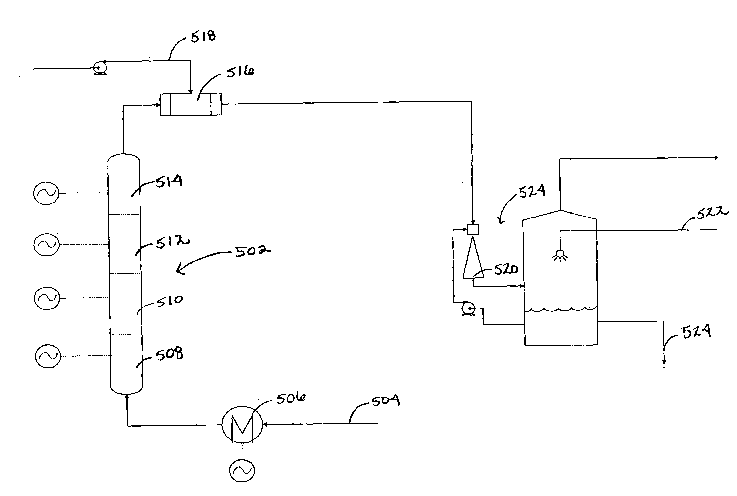
[00020] Figure 5 depicts a single pass hydrogen production system
according to an
illustrative embodiment of the invention.
[00021] Figure 6 is a graph showing equilibrium and operating curves for a
hydrogen
production system having a single pass configuration according to an
illustrative embodiment of
the invention.
DETAILED DESCRIPTION OF THE INVENTION
[00022] Disclosed is an Electric Reaction Technology (ERT) process and
apparatus
directed to the production of hydrogen and carbon solids by decomposition of
methane or natural
gas. The ERT apparatus may also be used for pyrolysis processes. When used for
the former,
the ERT process may also be called a fuel decarbonization process. The process
employs
4
PHDATA 1414087 8
CA 02642885 2008-08-13
WO 2007/095563 PCT/US2007/062109
electric resistance heaters capable of adaptation to the selective
decomposition of hydrocarbons
and filtration/separation equipment capable of effective filtration/separation
under very high
carbon loading.
[00023] As the source of electricity may be an environmental concern, such
a plant could
be situated near an economical and eco-friendly wind farm to provide the
necessary electricity.
There would be little or no resulting carbon dioxide or other greenhouse gas
emissions from
either one of these processes, as compared to conventional fossil fuel
technologies.
[00024] Hydrocarbon decomposition, also known as fuels decarbonization,
has been
neglected as a potential route for commercial hydrogen and carbon solids
manufacture and as a
process to mitigate global warming. Methane, the largest constituent in
natural gas, is also the
hydrocarbon with the highest hydrogen to carbon ratio. It therefore has the
potential to produce
relatively more hydrogen than any other hydrocarbon. Methane decomposition has
simple one-
step chemistry; and superior thermodynamics in that the chemical reaction
requires only 11.3
Kcal/mol of hydrogen, the lowest known process energy consumption per unit of
hydrogen
produced.
[00025] Methane Decomposition by Heating: (one non-catalytic step)
Methane Decomposition CH4 ¨> C + 2H2
Process Energy / Unit of Hydrogen +11.3 Kcal/mol hydrogen
[00026] This compares favorably with methane reforming by steam comprising
a two-
step, two-catalyst process that requires 18.8 Kcal/mol of hydrogen.
[00027] Methane Reforming by Steam: (two catalytic process steps)
Steam Reforming CH4 + H20 ¨> CO + 3H2
Water-Gas Shift CO + H20 ¨> CO2 + H2
Overall Reaction CH4 + 2H20¨> CO2 + 4H2
Process Energy / Unit of Hydrogen +18.8 Kcal/mol hydrogen
[00028] The first reaction (steam reforming) is highly endothermic and the
mols of
products exceed the mols of reactants, therefore, the reaction proceeds to
completion at high
temperature and low pressure. The second reaction (water-gas shift) is mildly
exothermic and
favors low temperature but is unaffected by pressure. The composition of the
products depend
PHDATA 1414087 8
CA 02642885 2008-08-13
WO 2007/095563 PCT/US2007/062109
upon the process conditions, including temperature, pressure, and excess
steam, which determine
equilibrium, as well as velocity through the catalyst bed, which determines
the approach to
equilibrium. All other proposed processes have far-inferior thermodynamics,
e.g. electrolysis
processes require approximately +106 Kcal/mol of hydrogen.
[00029] Methane decomposition schemes proposed and implemented by others
either have
very high capital costs arising from the complexity of high temperature
equipment designs or
have failed to perform reliably at commercial scale. Thus, it is apparent why
industry deploys
steam methane reforming for the majority of 'on-purpose' hydrogen production.
[00030] Hydrogen has long been an important gaseous raw material for the
chemical and
petroleum industries. Steam methane reformers are the basis of over 90% of the
world's on-
purpose hydrogen production. Presently such plants cost approximately $100
million to produce
100 MM SCFD of hydrogen. Particular embodiments of the disclosed methane
decomposition
plant are much simpler in concept and would be expected to cost substantially
less. Operating
margin analysis for feed and fuel and carbon solids at $4.50 / Million Btu
shows that the
disclosed process could breakeven with electricity priced as high as $95.50
per Megawatt-hour.
Conversely, with feed and fuel remaining at $4.50 / Million Btu and
electricity available at $40
per Megawatt-hour, hydrogen could be produced at breakeven for as little as
$5.78 per Million
Btu.
[00031] Carbon black is used primarily by the tire industry for the
production of
vulcanized rubber; however, it is also used as a black pigment for inks and
paints. The
worldwide demand for carbon black is predicted to increase 4% per annum
through 2008. With
respect to a hypothetical project to produce 50,000 mtpa of carbon black, the
following estimates
apply:
Natural Gas Feedstock 10.5 million standard cubic feet per
day
Electricity Consumption 18.3 megawatts
97.3 mol % Hydrogen Product 5,575 pounds per hour
Specific Electricity Consumption 2.91 kWh per kilogram of carbon
black; or
20.8 kWh per thousand SCF of hydrogen
Advantageously, particular embodiments of the disclosed invention may provide:
6
PHDATA 1414087 8
CA 02642885 2008-08-13
WO 2007/095563 PCT/US2007/062109
= Lower capital cost;
= Simplicity of design, operations and maintenance; and
= Margins between market and breakeven costs for electricity, hydrogen and
carbon
black;
= Analogous advantages that would apply for production from other
hydrocarbons.
[00032] The basic principle of the ERT process will now be described. When
methane (or
natural gas or other hydrocarbons) is heated above a certain temperature, it
will decompose to
hydrogen gas and carbon solids and absorb the heat of reaction as shown in the
chemical
equation above. The rate of decomposition increases with temperature. However,
the extent of
decomposition will reach an equilibrium level dependent on the temperature
level. After the
electrically heated screens within the ERT heat the gas, decomposition will
follow which will
tend to cool down the gas/carbon mixture. Since the time for heating is very
short relative to the
decomposition time, a space is allowed for reaction to take place after each
heating stage. The
ERT process is preferably constructed with multiple stages of heating and
reaction steps.
[00033] Following are illustrative configurations designed with different
design
constraints. Each description only highlights the main differences between the
various
configurations of the equipment required for each. The illustrative
configurations discussed
herein feature an optional quench cooling of the product carbon/gas mixture.
Several of the
configurations feature an optional pre-heater in order to heat the natural gas
feed to a higher
temperature to speed up the reaction, and accordingly the production of carbon
and hydrogen;
preheating also serves to minimize the electrical requirements that provide
the heat that drives
the chemical reactions. Due to concerns over the settling out of carbon
particles within the ERT
unit cross sectional flow area and flow rate have been selected to maintain
fluid velocity well
within the acceptable safe area of design.
[00034] The illustrative embodiments depicted in FIGS. 1, 3 and 5 show an
ERT unit
disposed vertically. The unit can also be disposed horizontally or at an angle
to the normal.
[00035] In an illustrative embodiment of the invention, the ERT unit is
set at
approximately 200 KW input to the ERT. In a preferred embodiment, the ERT is a
plug flow
reactor and consists of four (4) separate heating zones, each zone containing
four (4) screen
7
PHDATA 1414087 8
CA 02642885 2008-08-13
WO 2007/095563 PCT/US2007/062109
heater stations. This will be referred to as the Full Conventional
configuration and will be
discussed in more detail below.
[00036] FIG. 1 depicts an illustrative embodiment of the invention
referred to as
"Stagewise Configuration". This Stagewise Carbon Removal configuration
features a single
ERT unit 102 at its core as well as several finalizing reaction chambers 104,
106, 108, 110, 112.
The ERT unit is a single pass arrangement, meaning that the products are not
recycled back into
the process. This configuration is based upon running the reaction
adiabatically while utilizing
the product to heat the fresh natural gas feed 114. A hydrogen purity of 95.1
mol % is
potentially attainable with this particular design. The main design constraint
that was taken into
consideration while creating this configuration dealt with the temperature of
the carbon/gas mix
exiting each heating screen station. The goal was to find a design in which
the temperature of
the carbon/gas mix leaving each heating zone maintained approximately a 50F
approach to the
equilibrium temperature, meaning that each of the reaction chambers was
designed in such a way
that the exit temperature was at least greater than about 50F than the
equilibrium temperature at
the corresponding exit concentration of hydrogen. Calculated data is provided
in Table 1 at
nominal 300 pounds per square inch system pressure. This data is common to all
the illustrative
embodiments described herein. The methods and systems described herein are
applicable at
higher and lower pressures to be selected for each instance of use by
designers skilled in the art.
8
PHDATA 1414087 8
CA 02642885 2008-08-13
WO 2007/095563 PCT/US2007/062109
TABLE 1
DATA FOR EQUILIBRIUM CURVES
Equilibrium Data 50 F Approach
Temperature Mol Temperature Mol
Fraction Fraction
( F) Hydrogen ( F) Hydrogen
2800 0.98169 2850 0.98169
2700 0.98169 2750 0.98169
2600 0.98169 2650 0.98169
2500 0.98169 2550 0.98169
2400 0.97710 2450 0.97710
2300 0.97098 2350 0.97098
2200 0.96275 2250 0.96275
2100 0.95153 2150 0.95153
2000 0.93614 2050 0.93614
1900 0.91496 1950 0.91496
1800 0.88593 1850 0.88593
1700 0.84638 1750 0.84638
1600 0.79423 1650 0.79423
1500 0.72679 1550 0.72679
1400 0.64405 1450 0.64405
1300 0.54767 1350 0.54767
1200 0.44276 1250 0.44276
1100 0.33940 1150 0.33940
1000 0.23741 1050 0.23741
900 0.15248 950 0.15248
800 0.06995 850 0.06995
700 0.03854 750 0.03854
600 0.01879 650 0.01879
500 0.00789 550 0.00789
400 0.00273 450 0.00273
300 0.00073 350 0.00073
200 0.00013 250 0.00013
100 0.00001 150 0.00001
[00037] The natural gas feed enters a pre-heater 116, preferably at a
temperature of about
90 F and exits the pre-heater, preferably at a temperature of about 400 F.
The natural gas feed
then passes through a feed/product exchanger 118. This is a head to tail
heater that utilizes the
heat of the product carbon/gas mixture to heat the natural gas feed,
preferably to a temperature of
about 1000 F. The natural gas feed proceeds into the first heating screen
station 120 of the ERT
unit. A screen station may include one or more screens. The term "zone" will
also be used
9
PHDATA 1414087 8
CA 02642885 2012-05-18
herein. A zone includes one or more screen stations and is characterized by an
individual power
source. Upon leaving the first heating zone 120, the carbon/gas mixture has
preferably increased
to a temperature over about 2250 <0>F. After passing through each heating zone
120, 122, 124,
126, 128, the carbon/gas mixture passes through reaction and carbon removal
chambers 104,
106, 108, 110,112, respectively. These carbon product removal chambers will
allow for easy
sampling of the carbon formed throughout the ERT unit. Each subsequent heating
zone
gradually heats the remaining carbon/gas mixture in order to increase the
reaction rate, and thus
the rate at which carbon and hydrogen are produced. The flow through the ERT
unit can be said
to be once through, meaning that the products are not recycled back into the
system after
leaving the ERT unit. After passing through the fifth heating screen station
128, the carbon/gas
mixture preferably exits the ERT unit at a temperature of approximately 2250
F and passes
through final chamber 112 where it auto-cools to about 2160 F . The
carbon/gas mixture then
passes through several additional pieces of equipment, or the finalizing stage
130.
[00038] In this illustrative embodiment, the flow channel of each ERT unit
is about 5 feet
in length and is comprised of five heating zones 120, 122, 124, 126, 128
delivering a total heat
input of about 200 kW. The Stagewise Carbon Removal configuration will
preferably be
fabricated in such a way that each individual heating zone is immediately
followed by a large
carbon removal chamber 104, 106, 108, 110, 112. Each of the five ERT units
preferably consists
of a single heating screen station, each delivering a different heat duty to
the system. Since each
ERT zone is a separate unit, this simplifies electrical design and controls.
Immediately following
each ERT unit 120, 122, 124, 126, 128 is a carbon removal chamber 104, 106,
108, 110, 112 that
provides both a reaction volume and a settling location for the carbon
produced. Each removal
chamber is refractory-lined and water-jacketed and features continuous carbon
cooling and
removal. Removing the carbon from the heating duty of the system shortly after
it is produced
reduces energy input. Each of the heating zones in the respective ERT units
will deliver varying
amounts of heat to the system. Once again, this value is determined based upon
the design
constraint.
[00039] The finalizing stage is where the carbon/gas mixture is cooled and
separated. In
an illustrative embodiment of the invention, first, the carbon/gas mixture is
cooled as it passes
through a head to tail heat exchanger. The products will exit the exchanger,
preferably at a
temperature of about 500 F. Then the products go through a phase separator
134, such as a
CA 02642885 2008-08-13
WO 2007/095563 PCT/US2007/062109
Venturi scrubber, where water 136 is added, thus cooling the products and
creating slurry. The
carbon settles on the bottom of the apparatus and exits as slurry 138. Samples
can then be taken
before sending the product carbon slurry on for drying and final carbon
product production. The
remaining gas leaving the top of the phase separation apparatus comprises the
hydrogen product.
[00040] Calculated volume flow, heat duty, residence time, reaction
chamber outlet
temperature and outlet gas composition are shown in Table 2 for a five-section
Stagewise carbon
removal configuration. The associated equilibrium and operating curves are
shown in FIG. 2.
TABLE 2
STAGEWISE CARBON REMOVAL CONFIGURATION
Volumetric Volumetric
Volume Heat Duty Time
Outlet Outlet Mol
Flow In Flow Out
Section Temperature
Fraction
( F)
Hydrogen
(ft 3) (ft3/hr) (ft /hr) (kW) (sec)
1 15.037 4603 8258 83.0 8.418 1436 0.568
2 8.590 6431 8813 51.7 4.057 1662 0.790
0
a)
cr) 3 4.712 7622 8957 35.2 2.046 1882 0.889
Ui 4 2.827 8290 8968 21.3 1.180 2048 0.933
1.445 8629 8916 11.5 0.593 2160 0.951
There are several potential advantages to the Stagewise Carbon Removal
configuration:
= High hydrogen purity can be achieved.
= Carbon is removed after each individual heating screen station, thus
decreasing
the required heat inputs to each ERT unit.
[00041] This particular configuration only consists of five heating screen
stations; this
configuration can be expanded to include six or more heating screen stations.
Fewer heating
screens can also be used but will generally result in lower purity hydrogen.
Calculations show
95% hydrogen purity is potentially attainable with five stations as shown in
FIG. 2.
[00042] The next illustrative embodiment is referred to as a "Recycle
Configuration" and
is shown in FIG. 3. The Recycle configuration 300 is based upon recycling a
portion of the
11
PHDATA 1414087 8
CA 02642885 2012-05-18
reactor effluent back to the feed end of the ERT unit. This will enable the
use of a single heating
zone to be operated as the "final stage of ERT process." A simple ERT design
may be used to
obtain desired results. The Recycle configuration consists of an ERT unit 302,
reaction chamber
304, and a recycle system 306. A hydrogen purity of 95.5 mol % is potentially
attainable with
this design. The main design constraint dealt with controlling the temperature
of the carbon/gas
mixture exiting each heating screen station.
[00043] Following is a description of a recycle configuration according to
an illustrative
embodiment of the invention. The Recycle configuration features a loop design.
The natural gas
feed 308 enters the system, preferably at a temperature of about 90 F and is
injected into the
recycle stream at the feed side inlet 312 of a feed/product exchanger 314. The
exchanger 314
utilizes the heat of the recycle gas mixture to heat the natural gas feed and
the recycle gas/recycle
mix, preferably to a temperature of about 1000 F. The mixed feed proceeds
into the first
heating screen station 316 of the ERT unit. Upon leaving the first station
316, the carbon/gas
mixture has preferably increased to a temperature over 1600 F. Each
subsequent heating screen
station 318, 320, 322 gradually heats the carbon/gas mixture to a higher
temperature in order to
increase the reaction rate. After passing through the fourth heating screen
station 322, the
carbon/gas mixture exits the ERT unit 302 at a temperature of preferably
nearly 2700 F and
flows to the reaction chamber where it auto-cools to about 2200 F.
[00044] In this illustrative embodiment, the ERT unit 302 itself is 12
feet in length and is
comprised of four heating screen stations 316, 318, 320, 322, preferably
delivering a total heat
input of about 80 kW. The Recycle ERT unit is preferably substantially
vertical to allow the gas
flow through the ERT unit 302 to carry the carbon with it, preventing or
minimizing build up of
carbon on the screens or on the walls of the ERT unit 302. The ERT unit 302
preferably has a
first heating screen station 316 where preheating takes place, three
additional heating screen
stations 318, 320, 322 where the reaction takes place. The primary function of
the first heating
screen station 316 is to heat the mixed gas feed in order to increase the rate
of reaction. Minimal
amounts of carbon and hydrogen are produced during this stage due to the slow
rate of reaction.
Therefore, the spacing between the first screen station 316 and the second
screen station 318
does not need to be very large, however, due to design constraints, as well as
trying to maximize
the hydrogen purity, the spacing between the first and second screen stations
316, 318 is
preferably moderately large. Once the carbon/gas mixture reaches temperatures
over 1500 F,
12
CA 02642885 2012-05-18
noticeable amounts of carbon and hydrogen are produced: consequently, the
remaining heating
screen stations 318, 320, 322 preferably have larger spacing between them.
Preferably, the heat
delivered by each heating screen station does not vary; each heating screen
station in both the
pre-heating area and reaction area ideally delivers 20 kW to the system in
this particular
embodiment. By varying the spacing between each heating screen station
throughout the entire
ERT unit 302, higher hydrogen purity will likely be achieved.
[000451 The reaction mix from the ERT 302 unit flows to the reaction
chamber 304. The
chamber 304 adds the residence time needed for high hydrogen purity to be
achieved. By the
time the gas leaves the reaction chamber 304, the temperature of the
carbon/gas mixture has
preferably dropped to approximately 2200 F. The carbon/gas mixture then
proceeds to go
through a splitter (not diagrammed, but indicated at 324) where the product
stream is separated.
In an illustrative embodiment of the invention, approximately 40% of the
products and the
mixture is then sent through a quench cooling system 326 where they are
cooled, preferably to
about 500 F with quench water. The products then go through a phase separator
328, such as a
Venturi scrubber, where the carbon/gas mixture is cooled further by contacting
with a circulating
slurry of water and carbon. Make up water 330 is added to the phase separation
system 328, thus
cooling the products and creating slurry. Other compatible cooling and
separation systems, are
within the spirit and scope of the invention. The product carbon settles on
the bottom of the
apparatus and exits as slurry at outlet area 332. Samples can then be taken
before sending the
product carbon slurry on for drying and final carbon product production. The
remaining
'cleaned gas' leaving the top of the phase separation apparatus substantially
carbon-free,
containing a mixture of methane and hydrogen comprises the hydrogen product.
[00046] The remaining 60% of the reaction chamber effluent is the recycle
gas. It passes
through the feed/product exchanger 314 where it is cooled by the feed and
recycle mix stream
preferably to about 900 F. The huge drop in temperature is due to the fact
that the heat of the
product stream is used to heat the feed stream, which is much cooler (about
200 F). The recycle
mixture is then passed through an air cooler 334 where it is preferably cooled
to about 200 F
before it passes through a compressor 336, which compresses the recycle stream
to the required
feed inlet pressure. The carbon/gas recycle mixture is then injected with
fresh natural gas after
passing through the compressor 336.
13
CA 02642885 2008-08-13
WO 2007/095563 PCT/US2007/062109
[00047] Table 3 shows calculated volumes, heat duties, residence times,
outlet
temperatures and compositions for a four-section Recycle Configuration system.
The associated
equilibrium and operating curves are shown in FIG. 4.
TABLE 3
RECYCLE CONFIGURATION
Volume
Volumetric Volumetric Heat Duty Time Outlet Outlet Mol
Section Flow In Flow Out Temperature
Fraction
(ft3) (ft3/h r) (ft3/h r) kW (sec) ( F)
Hydrogen
1 0.380 4700 4724 20.0 0.291 1600 0.704
2 0.380 4712 4927 20.0 0.284 2014 0.732
0
a)
cr)
3 0.543 4820 5515 20.0 0.379 2240 0.818
Ui
4 2.365 5167 6305 20.0 1.484 2198 0.955
[00048] The Recycle configuration has several potential advantages:
= Very high hydrogen purity can be achieved due to the gas mixture entering
the ERT unit at a very high temperature and already containing hydrogen.
The finishing reaction chamber at the end of the ERT unit also contributes
to the high hydrogen purity that can potentially be achieved. The large
finishing reaction chamber adds residence time to the system, meaning
that the reaction has a longer time to progress, thus resulting in more
conversion.
= The ERT unit itself can be moderately sized and priced.
= Uniform heat delivered by each heating screen station can help to
simplify
the electrical controls and thereby may reduce costs compared to variable
heat input configurations.
= The Recycle configuration can operate over a wide range of desired outlet
conditions by varying the recycle ratio and overall heat input.
14
PHDATA 1414087 8
CA 02642885 2008-08-13
WO 2007/095563 PCT/US2007/062109
[00049] FIG. 5 depicts an illustrative embodiment of a system referred to
as a "Full
Conventional Configuration." The Full Conventional configuration features a
single, large ERT
unit 502 and the flow or reactant or reaction mix is once through, meaning
that the products are
not recycled back into the process. This configuration is based upon the
concept of minimizing
reaction time, and consequently reaction volume, by reaching a high reaction
temperature (over
2500 F) quickly and running most of the reaction as close to isothermal
conditions as possible.
A hydrogen purity of 97.2 mol % is potentially attainable with this particular
design. The main
design constraint dealt with temperature of the carbon/gas mixture exiting
each heating screen
station. Preferably, the range of the temperature of the carbon/gas mixture
leaving each heating
screen station is within a small range of the temperature of the carbon/gas
mixture entering that
heating screen station (approximately 150 F). By maintaining high
temperature, the rate of
reaction is maximized and the residence time minimized.
[00050] The overall system design can be relatively simple. Natural gas
feed 504 enters a
small pre-heater 506, preferably at a temperature of about 90 F and is
preferably heated to a
temperature of about 400 F. The natural gas feed proceeds into the ERT unit
502. Upon
leaving a first screen station within heating zone 508, the carbon/gas mixture
has preferably
increased to a temperature over 1000 F. Each subsequent heating screen
station in zone 508,
gradually heats the carbon/gas mixture to the target isothermal zone
temperature range of 2200
F to 2500 F in order to increase the reaction rate, and thus the rate at
which carbon and
hydrogen are produced. After passing through the last heating screen station,
the carbon/gas
mixture preferably exits the ERT unit 502 at a temperature of about 2600 F
and flows to the
finalizing stage. Appropriate near-equilibrium attainment time is provided in
the ERT outlet and
interconnecting piping.
[00051] The ERT unit 502 is approximately 40 feet in length and consists
of sixteen
heating screen stations (not shown) delivering a total heat input of about 260
kW. The Full
Conventional ERT unit 502 is preferably vertical, to allow the gas flowing
through the ERT to
pneumatically convey the carbon with it, preventing or minimizing build up of
carbon on the
screens or on the walls of the ERT. The ERT unit preferably has four zones
508, 510, 512, 514
with four heating screen stations in each (not shown). The primary function of
the first zone 508
is to heat the natural gas feed 504 in order to increase the rate of reaction.
Due to the slow
reaction rate at lower temperatures, minimal amounts of carbon and hydrogen
are produced
PHDATA 1414087 8
CA 02642885 2008-08-13
WO 2007/095563 PCT/US2007/062109
during this stage; therefore, the spacing between each heating screen station
does not need to be
very large and does not need to vary over the course of the zone. Once the
carbon/gas mixture
reaches temperatures over 1500 F, the reaction rate increases and noticeable
amounts of carbon
and hydrogen are produced: consequently, the remaining three zones 510, 512,
514 have larger
spacing between each heating screen station than does the first zone.
Preferably, the heat
delivered by each heating screen station remains constant within each zone,
which allows for
some simplification in the design of the ERT unit 502. The heat delivered by
each heating
screen station in the first zone is preferably 30 kW. The total heat duties
delivered by each
subsequent zone preferably decreases. The heat delivered by each heating
screen station in the
second zone 510 is 22.5 kW, while the heat duty delivered in the third zone
512 is 9.5 kW. The
heat duty delivered by each heating screen station in the final zone 514 is
only 2.4 kW. The
reaction rates and residence times necessary to achieve the desired conversion
to hydrogen and
carbon depend, at least in part, on the heating screen station spacing.
Preferably, the heating
screen station spacing varies continuously after the first zone 508 in order
to maintain near
isothermal conditions.
[00052] The finalizing stage is where the carbon/gas mixture is cooled and
separated.
First, the carbon/gas mixture passes through a quench cooling system 516 where
quenching
water 518 is injected. The products will exit the quench cooling system,
preferably at a
temperature of about 500 F. The products then go through a phase separator
520, such as a
Venturi scrubber, where the carbon/gas mixture is cooled further by contacting
with a circulating
slurry of water and carbon. Make up water 522 is added to the phase separation
system 524, thus
cooling the products and creating slurry. The carbon settles on the bottom of
the apparatus and
exits as slurry. Samples can then be taken before sending the product carbon
slurry on for drying
and final carbon product production. The remaining 'cleaned gas' leaving the
top of the phase
separation apparatus substantially carbon-free, containing a mixture of
methane and hydrogen
comprises the hydrogen product.
[00053] Table 4 provides calculated volumes, flow rates, heat duties,
residence times,
outlet temperatures and outlet compositions for a sixteen section, single pass
configuration. The
associated equilibrium and operating curves are shown in FIG. 6.
16
PHDATA 1414087 8
CA 02642885 2008-08-13
WO 2007/095563 PCT/US2007/062109
TABLE 4
FULL CONVENTIONAL CONFIGURATION
Volume
Volumetric Volumetric Heat Duty Time Outlet Outlet Mol
Section Flow In Flow Out Temperature
Fraction
(ft3) (ft3/hr) (ft3/hr) kW (sec) ( F)
Hydrogen
1 0.054 4600 4600 30.0 0.043 1033 0.000
2 0.054 4600 4610 30.0 0.042 1527 0.002
3 0.054 4600 4680 30.0 0.042 1947 0.017
4 0.054 4640 4930 30.0 0.041 2294 0.075
0.380 4784 6650 22.5 0.240 2218 0.389
6 0.380 5714 7020 22.5 0.215 2256 0.554
c
o 7 0.380 6370 7710 22.5 0.195 2288
0.692
..=
O 8 0.380 704 8000 22.5 0.315 2408
0.776
a)
u)
1- 9 0.489 7520 8300 9.5 0.223 2372 0.836
fl
w 10 0.489 7910 8380 9.5 0.216 2411 0.869
11 0.489 8140 8570 9.5 0.211 2462 0.898
12 0.489 8350 8740 9.5 0.206 2524 0.923
13 0.163 8550 8550 2.4 0.069 2564 0.923
14 0.163 8550 8690 2.4 0.068 2569 0.931
0.163 8612 8740 2.4 0.068 2578 0.939
16 1.537 8680 9180 2.4 0.620 2411 0.972
[00054] The Full Conventional configuration has several potential
advantages.
= Very high hydrogen purity may be achievable with this particular design.
= The kinetics of this particular system favors both high temperatures and
a
long residence time in order to achieve high hydrogen purity.
= The Full Conventional configuration can use near isothermal high
temperatures to minimize residence time.
= A minimal amount of equipment is required for particular embodiments of
this configuration.
= The quench cooling system that is used to cool the carbon/gas product is
relatively inexpensive in comparison to a more complex and costly recycle
system.
17
PHDATA 1414087 8
CA 02642885 2008-08-13
WO 2007/095563 PCT/US2007/062109
= Embodiments of this particular configuration may be highly efficient in
terms of energy input per amount of product produced for a full-scale
industrial process.
[00055] The invention may be embodied in a variety of ways, for example, a
system,
method, device, etc.
[00056] The high-level heat energy capable of being produced by
embodiments of the
invention can be integrated into other electrical or chemical processes.
Accordingly, the
invention is not limited to the uses described above. As an example, the
effluent can be used as a
heat source for a solid oxide fuel cell.
[00057] Still further, the carbon produced can be used for various
applications. For
example, it can be used for molten carbonate fuel cells (MCFC). MCFCs use an
electrolyte
composed of a molten carbonate salt formed by mixing carbon or a carbon
precursor with a salt.
[00058] As noted above, the ERT apparatus can be used for pyrolysis of
hydrocarbons,
such as ethane, propane, butane, naphtha, or any hydrocarbon feedstock that
can be vaporized.
In an illustrative example, an ERT apparatus analogous to that depicted in
FIG. 5 is used to
pyrolyze hydrocarbon gas. The hydrocarbon feedstock is preferably preheated to
approximately
400 F and then is fed through the ERT system. The heat produced by the ERT
system pyrolyzes
the hydrocarbon feedstock. The pyrolyzed gas is then passed through a
quenching system,
preferably immediately after exiting the ERT apparatus. The resulting cracked
gas products then
undergo separation using conventional separation methods. Hydrogen, methane,
and various C25
C3, C4, C5 and heavier components can be separated and heat recovered. The
separated hydrogen
can be recycled in the system. In a preferred embodiment, the pyrolysis system
is designed for
lesser pressure and lesser residence times than the systems used for
decarbonization and the
quenching of the gases exiting the ERT is designed for minimum residence time
to stop free-
radical chemical reactions rather than to allow additional time for the gases
to approach
equilibrium as in the decarbonization systems. Further, the gas processing
time-temperature
relationship can be managed in pyrolysis modes to optimize economically the
cracked gas
product spectrum. In pyrolysis operations, steam may be added to the feedstock
as it serves to
reduce hydrocarbon partial pressure thereby enhancing yield spectra and it may
reduce any
tendency for carbon formation. A minimal amount of carbon monoxide and carbon
dioxide will
18
PHDATA 1414087 8
CA 02642885 2012-05-18
form but the short residence time will tend to preclude much steam reforming
of the hydrocarbon
feedstock.
[00059] An illustrative ERT apparatus is approximately six feet long,
having
approximately sixteen screens, each separated by approximately four inches.
19