Note: Descriptions are shown in the official language in which they were submitted.
CA 02642895 2008-08-19
WO 2007/096188 PCT/EP2007/001597
Clamping Chuck The present invention relates to a clamping chuck for a
rotatably driven machine tool as
defined in the preamble to Patent Claim 1.
Because of the sliding sleeve that is used to hold the shaft of the machine
tool, e.g. a tool
holder, clamping chucks of this kind are also referred to as quick clamping
chucks.
All that is required in order to change the tool is to displace the sliding
sleeve so that the
clamping body that is acted upon by the sliding sleeve can move freely within
the wall
opening in which it sits.
The shaft of the machine tool is thereby released and can simply be withdrawn
from the
clamping chuck.
It is the objective of the present invention to create a clamping chuck of
this kind that is
of simple construction, with which, in particular, rapidly rotating miniature
machine tools
with shaft diameters of only a few millimeters can be so manufactured with
simple means
that, on the one hand, they can be rapidly replaced and, on the other, are
accommodated
and torsionally secured automatically.
The present invention achieves this objective with the features set out in the
main Claim.
The present invention is characterized in that in the end position that it
assumes under the
action of the initial spring loading, an internal collar on the clamping body
lies in contact
on the clamping body that, in its turn, exerts an appropriately great lateral
pressure on the
cylindrical shaft of the machine tool. Since the shaft of the machine tool has
a secantial
groove or a secantial flat that does not, however, rotate, at the point where
the clamping
body sits, this also provides for torsion-proof clamping when the clamping
body rests on
the flat or the secantial groove.
1
CA 02642895 2008-08-19
WO 2007/096188 PCT/EP2007/001597
The clamping body thus performs a dual function. On the one hand, it secures
the shaft
of the tool in the axial direction and it also serves as a torque preventing
lock because of
the relatively small torsion moments that act on the shaft of the tool. In the
event that the
secantial groove falls in the axial direction to a deepest point, an axial
force can be
exerted on the shaft of the tool as far as a depth stop.
More advantageously, to this end the shaft of the machine tool has at the
appropriate
location a bore or-which is simpler to produce-a secantially formed groove
within
which the clamping body engages when the sliding sleeve is displaced in the
direction of
the spring force that is exerted.
It is the dual function of the clamping body in conjunction with the
cylindrical bore in the
base body that greatly simplifies manipulation.
This advantage is achieved in that when the shaft of the tool rotates, the
clamping body
automatically enters the secantial groove.
In addition, the base body can be penetrated axially by a cylindrical bore to
accommodate
the shaft of the tool, because the transfer of torque is effected by way of
the clamping
body.
As discussed, one measure to achieve relatively high turning moments is the
incorporation of a secantial groove on the shaft of the tool.
Another measure is based on the idea that the clamping body fits positively on
the shaft
of the tool and, as a consequence, permits an initial turning moment of the
tool shaft until
it enters the secantial groove.
For this reason, as a result of appropriate measures, a self-amplifying
clamping effect can
be initiated in the peripheral direction, if the clamping body is tilted, for
example, in the
wall opening.
2
CA 02642895 2008-08-19
WO 2007/096188 PCT/EP2007/001597
As a final measure, it would also be possible to so configure the internal
collar of the
sliding sleeve, which fits on the clamping body outside the opening in the
wall, that even
in the event of a slight rotation of the tool shaft, there will be forcible
clamping by the
clamping body.
What is and remains important is the dual function, since the clamping body
provides for
axial retention as well as security in the direction of a possible turning
moment of the tool
shaft.
The advantageous developments are set out in the secondary claims.
In particular in the case of conventional machine tools with a thin shaft with
a diameter
measuring 3 to 4 mm, combined with the very high rotational speeds of up to
30,000 rpm
that are usual today, there will be resonant vibrations in the lower third of
the tool shaft in
the event of tight clamping, and in the final analysis this can lead to the
machine tool
vibrating.
It is here that one development of the present invention helps. In this, the
base body
offers centering for the tool shaft in the head area. This can be achieved,
for example, in
that the base body has an internal groove on the insertion side and a ring of
elastomer
material is fitted into this.
The inside diameter of the installed ring is somewhat smaller than the outside
diameter of
the tool shaft, so that here there is additional radial clamping of the tool
shaft, with
the help of which the freely vibrating length of the tool shaft is reduced
between the
point of application of the clamping body and the seat of the tool itself.
Because of this, the amplitude of vibration can be greatly reduced, whereas at
the same
time the natural frequencies are increased.
3
CA 02642895 2008-08-19
WO 2007/096188 PCT/EP2007/001597
Thus rough running of the machine tool because of the deleterious natural
frequencies is
reliably avoided.
The present invention will be described in greater detail below on the basis
of
embodiments shown in the drawings appended hereto. These drawings show the
following;
Figure 1: a first embodiment of the present invention in longitudinal cross
section;
Figure 2a: a possible embodiment of an associated tool shaft;
Figure 3: a further embodiment of the present invention in the operating
position;
Figure 4: an embodiment as in Figure 3 in the insertion position.
Insofar as nothing to the contrary is stated in the following description, it
applies to all of
the figures.
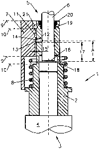
The drawings show a clamping chuck 1 for a rotatably driven machine tool.
The machine tool is not shown: only the shaft 6 of the machine tool is shown.
The clamping chuck has a central hollow cylindrical base body 2. The base body
2 has a
drive end 3 for the spindle 4 of the machine tool and opposite this an
insertion end 5 for
the shaft of a machine tool.
The base body 2 is surrounded by a sliding sleeve 7 that in this instance is
spring loaded
toward the insertion end 3.
The sliding sleeve 7 can also be spring loaded in the other direction. In this
case, the
following apply accordingly.
The spring loading is applied by a compression spring 8 that is located
between an
external collar of the base body 2 and an internal step of the sliding sleeve
7.
4
CA 02642895 2008-08-19
WO 2007/096188 PCT/EP2007/001597
The sliding sleeve 7 can move between a front end position 9 and a rear end
position 10.
It has a circumferential internal groove 11 that, in the end position 10
predetermined by
the compressed compression spring 8, lines up with an opening 12 in the wall
of the base
body 2.
There is a clamping body 14 within the opening 12 in the wall, and the radial
dimensions
of this are greater than the thickness of the wall of the base body 12 at the
location of the
wall opening 12.
If necessary, radial clearance 15 between the internal collar 13 of the
sliding sleeve 7 and
the outside diameter of the base body 2 at the location of the wall opening
must also be
taken into consideration.
The internal collar 13 is arranged at a location on the sliding sleeve 7 that,
in the front end
position 9 of the sliding sleeve 7, is opposite the wall opening 12, when the
sliding sleeve
is being acted upon by the spring tension of the compression spring 8,.
The clamping body is thereby inevitably held securely in the secantial groove
22 of the
tool shaft.
It is essential that, in the longitudinal area in which the shaft 6 of the
machine tool is
located, the hollow cylindrical base body 2 be cylindrically hollow so that it
can
accommodate the cylindrical shaft of the machine tool.
The inside diameter of this cylindrical cutout thus corresponds to the outside
diameter of
the cylindrical shaft of the machine tool, so that the shaft 6 can in
principle rotate freely
within the bore of the base body 2.
CA 02642895 2008-08-19
WO 2007/096188 PCT/EP2007/001597
Furthermore, in the position of the sliding sleeve 7 in which the internal
collar 13 rests on
the clamping body 14, in which the internal collar 13 of the sliding sleeve 7
is aligned
with the wall opening 12, said clamping body 14 serves both as axial as well
as a torque-
proof clamping device of the cylindrical shaft 6 of the machine tool, because
the shaft of
the machine tool has the secantial groove at a more suitable position.
For this reason, the clamping body 14 has a double function.
On the one hand, it prevents the shaft 6 of the machine tool from falling out
in the axial
direction, whereas at the same time a clamping function is provided in the
peripheral
direction.
It is important that the wall opening 12 be spaced apart from a depth stop 16,
against
which-in the embodiment shown in Figure 1-the face surface of the inserted
shaft 6
abuts, by a predetermined distance 17.
Then the secantial groove can be configured with a sloping face at one
location, against
which the clamping body comes to rest when the shaft 6 of the machine tool
rests against
the depth stop. This ensures the axial clamping function.
In this way, it is ensured that the shaft 6 is clamped in the middle area, so
that despite the
unavoidable radial play of the tool shaft 6 in the cylindrical bore of the
base body 2,
which is a consequence of the transition fit, only limited free vibrations can
result.
Because of the clamping body 14, what is created is a clamping point of the
shaft 6 that is
displaced towards the middle of the shaft, so that any possible resonance
vibrations that
occur will be of low amplitude, and even then only at high frequencies.
The dimension 17, which determines the distance to the clamping body between
the
depth stop 16 and the clamping point of the shaft 6, thereby serves to reduce
the length of
the shaft 6 that is involved in possible resonance vibrations.
6
CA 02642895 2008-08-19
WO 2007/096188 PCT/EP2007/001597
In the case of Figure 1, the depth stop 16 is formed by a pin 18 that passes
transversely
through the base body 2.
The pin is arranged in front of the head end of the machine spindle 4 and is
seated in a
radial bore that passes transversely through the base body 2.
When the shaft 6 is inserted, its advancing face end contacts the transverse
pin 18 and can
then be held rigidly both axially and in the peripheral direction by releasing
the sliding
sleeve 7 from the clamping body 14 as soon as the clamping body drops into the
secantial
groove.
Since the sliding sleeve 7 is held in this end position against the upper
locking ring 21 by
the compression spring 8, the shaft 8 is securely clamped.
The locking ring can also be identified by being coloured, so as to indicate
whether or not
that the sliding sleeve is fully extended.
Should it be desired to further reduce the free vibrating length of the
inserted shaft 6, one
can provide a circular internal groove 19 in the area of the head end of the
base body 2,
within which is installed a ring of elastomer material.
On the one hand, this ring possesses good damping properties and, in addition,
can have
an inside diameter that is somewhat smaller than the outside diameter of the
shaft 6.
This applies in the same way to the round cylindrical cut-out in the base body
2, into
which the shaft 6 of the machine tool is inserted.
As a consequence of the then elastic but zero-clearance encirclement of the
shaft 6 at the
location that is displaced the furthest in the direction of the tool, the
length dimensions
7
CA 02642895 2008-08-19
WO 2007/096188 PCT/EP2007/001597
that are possibly involved in a free vibration are further reduced and as a
consequence of
this the amplitude is reduced and the frequency increased.
The elastomer ring 20 can, for example, be of rubber or silicon or a similar
material.
A centering device in the form of a clamp or steel springs can be used instead
of the
elastomer ring. A conical seat that forms a centering cone 26, as in Figure 3
and Figure
4, can also be used. A correspondingly configured tool shaft fits in this. At
the place
where its diameter is smallest, the conical seat also forms the depth stop 16.
This version
is suitable, in particular, in the case of shaft diameters that are greater
than 3 mm to 4
mm, for example, 6 mm to 12 mm or more.
Figure 2 also provides a detailed view of a shaft 6 that is acted upon by the
clamping
body 14 at a predetermined distance A, measured from the face surface of the
insertion
end.
The distance A is calculated from that enveloping line of the pin 18 that
limits the
insertion depth of the shaft 6 in the clamping chuck 1 as far as the point
where the
clamping body 14 acts on the shaft 6.
In order to achieve particularly high torque-proof clamping, it is proposed
that a tool shaft
6 of this kind be provided with a groove 22 that extends only part-way round
part of the
periphery so that the clamping body 14, which is held in the clamping position
by the
internal collar 13, actually exerts a clamping effect on the shaft 6 in the
peripheral
direction, and this results in torque-proof clamping.
If the shaft 6 is rotated, the clamping body is pressed against the inner
collar 13 in the
peripheral direction and in this way is subjected to pressure. Since the
clamping body 14
cannot move radially, the required clamping function is ensured in the
peripheral
direction.
8
CA 02642895 2008-08-19
WO 2007/096188 PCT/EP2007/001597
The internal collar 13 prevents the clamping body from moving radially to the
outside so
that the torque that is exerted by the machine spindle 4 is transferred
through the
clamping function of the clamping body 14 completely onto the shaft 6 of the
machine
tool in the peripheral direction.
If the clamping body 14 also acts on a slope 25 of the secantial groove 22,
the axial
clamping is unshakeably firm. This can be implemented in the cross-hatched
area of the
secantial groove as in Figure 2.
9
CA 02642895 2008-08-19
WO 2007/096188 PCT/EP2007/001597
Key to Drawings
I clamping chuck
2 base body
3 drive end
4 machine spindle
insertion end
6 shaft of machine tool
7 sliding sleeve
8 compression spring
9 front end position
rear end position
11 internal groove
12 wall opening
13 internal collar
14 clamping body
radial clearance
16 depth stop
17 space
18 pin
19 internal groove
elastomer ring
21 locking ring
22 groove
23 internal thread
24 machine spindle
inclined face
26 centering cone
A space