Note: Descriptions are shown in the official language in which they were submitted.
CA 02643129 2013-03-20
54106-191
- 1 -
Overcurrent switching apparatus
BACKGROUND OF THE INVENTION
FIELD OF THE INVENTION
The invention relates to an overcurrent switching apparatus for
medium-voltage or high-voltage applications having current detection
means for switching a contact system, which is associated with them,
from a first state to a second state when a threshold current is
exceeded.
An electronics module having an overcurrent switching apparatus such
as this is known from international patent application PCT/DE
2005/001147, which is regarded as prior art. In this prior
overcurrent switching apparatus, a connecting conductor has a
deformable section as current detection means. The deformable section
is deformed when a threshold current is exceeded, such that a contact
system is switched from a first state to a second state. The
deformable section is in this case also used to form the contact
system in that, together with a contact part, it forms the contact
system.
SUMMARY
The object of some embodiments of the present invention is to design
an overcurrent switching apparatus which can be designed flexibly and
precisely as appropriate for the respectively stated requirements.
According to some embodiments of the invention, this object is
achieved in that the current detection means which are located in a
first current branch are followed via coupling means by operating
means which are designed to switch the contact system, which is
located in a second current branch, from the first state to the
second state.
CA 02643129 2013-03-20
54106-191
- 2 -
One major advantage of the overcurrent switching apparatus
according to some embodiments of the invention is that the current
detection means as well as the coupling and operating means in it
represent assemblies and elements, respectively, in their own
right, and can therefore be designed in their own right and can
have appropriate dimensions; this also applies to the contact
system, because this forms a system in its own right, on which the
operating means act. This all allows precise adjustment and a
wide adjustment range for the threshold current, in which the
contact system can be switched from its first state to its second
state. In this case, the contact system can advantageously be
used in a flexible form to the extent that the first state of the
contact system may be the open state and the second state may be
the closed state of the contact system, or vice versa, such that
an opening or a closing overcurrent switching apparatus is
provided in a simple manner, depending on the respective
requirements. This also results in the advantageous capability to
carry out a switching process in the second current branch when an
overcurrent occurs in the first current branch.
In one preferred embodiment, the current detection means comprise
two busbar sections which run parallel to one another, in which
the current is carried in opposite senses and of which at least
one section can be deformed, wherein the deformable section can
be changed from a normal position to an operating position by the
threshold current being exceeded. In a refinement such as this,
an electromagnetic force advantageously acts between the
parallel-running conductors which carry currents in opposite
senses, such that the deformable section is deformed by this
force when a threshold current is exceeded, and is changed from a
normal position to an operating position. In this case, the
threshold current can easily and flexibly
CA 02643129 2008-08-21
:
PCT/DE2006/000345 - 3 -
2006P01121WOUS
be adjusted via the deformation capability of the deformable
section.
In a further refinement of the invention, the coupling means
comprise a blocking element which is firmly connected to the
deformable section. A blocking element such as this, for
example a holding pin, is a simple option for coupling the
current detection means to the operating means.
In one preferred embodiment, the operating means comprise an
operating member which can be spring-loaded and is designed
such that, when a blocking element is in the normal position of
the deformable section, the operating member is held in a
position with a stressed spring and is released in an operating
position of the deformable section. An operating member such as
this can be released in a simple manner by the blocking
element, thus advantageously allowing the contact system to be
switched quickly from its first state to its second state.
The operating member may be formed in various ways, for example
as a plunger. In one particularly preferred refinement, the
operating member is a moving carriage which can be stressed by
means of the spring and has a rigidly connected guide rod. A
carriage such as this can particularly advantageously be held
or released by the blocking element.
In a further refinement, the contact system is formed from a
moving contact which is rigidly connected to the operating
means, in order to form a conductive connection between a first
and a second opposing contact. The opposing contacts may in
this case both be in the form of fixed contacts. If required,
it may also be advantageous for one opposing contact
CA 02643129 2008-08-21
PCT/DE2006/000345 - 4 -
2006P01121WOUS
to be in the form of a fixed contact and for the other opposing
contact to be in the form of a flexible contact, in which case,
for example, the flexible contact can be produced using a
flexible connecting line. A contact system such as this can
easily be switched from its first state to its second state by
the operating means.
In another preferred embodiment, the current detection means
comprise a coil which surrounds connecting conductors which
carry the current. A coil allows an overcurrent to be detected
in a precise manner since a current flowing in the connecting
conductor in the coil induces a voltage by means of which the
operating means can be operated in a simple manner.
In a further refinement of the invention, the contact system
comprises an electrical switch which is connected to the coil
via the coupling means and the operating means and which can be
switched from the first state to the second state by a voltage
induced in the coil when the threshold current is exceeded. An
electrical switch advantageously has fast and precise
adjustable switching characteristics in order to switch the
contact system from the first state to the second state, with
the switch being designed such that it remains in the second
state, once it has been switched to this state.
In one expedient embodiment, the electrical switch is a
thyristor. A thyristor is a precise electronic switching
element as an electrical switch, which can easily be operated
directly by the voltage induced in the coil.
CA 02643129 2013-03-20
54106-191
- 5 -
In another embodiment, the electrical switch is an
electromagnetically operated switch. An electromagnetically
operated switch which is controlled by the coil allows precise
and fast switching in a simple manner.
In a further refinement, the operating means comprise a control
apparatus for the electrical switch. A control apparatus is
advantageous for precise adjustment of the threshold current to
be detected.
Some embodiments of the invention also relate to a bridging
apparatus for an electronics module, such as that disclosed in
the prior international patent application PCT/DE 2005/001147
which was mentioned initially, and have the object of
developing a bridging apparatus such as this for an electronics
module such that it has a flexible design with a precise
adjustable threshold current.
According to some embodiments of the invention, a bridging
apparatus for an electronics module is used to achieve the
object, having an overcurrent switching apparatus in one of the
refinements described above, wherein the current detection
means are designed to switch the contact system associated with
them from a first state, in which the electronics module is
connected to a circuit arrangement, to a second state, in which
the electronics module is bridged in the circuit arrangement,
when a threshold current is exceeded in the electronics module.
This bridging apparatus advantageously allows a flexible design
with a precise adjustable threshold current. The bridging
apparatus therefore forms an advantageous application of the
overcurrent switching apparatus according to the invention and
can advantageously be used, for example, to bridge an
CA 02643129 2013-03-20
54106-191
- 6 -
electronics module according to German laid-open specification
DE 101 03 031 Al.
In a further refinement, the contact system is conductively
connected to connecting terminals of the electronics module.
This ensures that the electronics module is bridged in a simple
manner when the threshold current is exceeded, by provision of
a conductive connection between the connecting terminals via
the contact system.
According to one aspect of the present invention, there is
provided an overcurrent switching apparatus for medium-voltage
or high-voltage applications having current detection means for
switching a contact system, which is associated with them, from
a first state to a second state when a threshold current is
exceeded, wherein the current detection means which are located
in a first current branch are followed via coupling means by
operating means which are designed to switch the contact
system, which is located in a second current branch, from the
first state to the second state, and wherein the current
detection means comprise two busbar sections which run parallel
to one another, in which the current is carried in opposite
senses and of which at least one section can be deformed,
wherein the deformable section can be changed from a normal
position to an operating position by the threshold current
being exceeded.
According to another aspect of the present invention, there is
provided a bridging apparatus for an electronics module having
an overcurrent switching apparatus as described herein, wherein
the current detection means are designed to switch the contact
system associated with them from a first state, in which the
CA 02643129 2013-03-20
54106-191
- 6a -
electronics module is connected to a circuit arrangement, to a
second state, in which the electronics module is bridged in the
circuit arrangement, when a threshold current is exceeded in
the electronics module.
In a further refinement of the invention, the current detection
means detect the current in the electronics module.
BRIEF DESCRIPTION OF THE DRAWINGS
The invention will be explained in more detail in the following
text on the basis of the drawing and of exemplary embodiments,
with reference to the attached figures, in which:
figure 1 shows a schematic illustration of an
overcurrent switching apparatus according to the invention, in
a first refinement of a bridging apparatus according to a first
embodiment; and
figure 2 shows a schematic illustration of an
overcurrent switching apparatus according to the invention in a
second refinement of a bridging apparatus according to a second
embodiment.
DETAILED DESCRIPTION
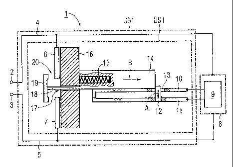
Figure 1 shows an overcurrent switching apparatus 0S1 of a
bridging apparatus OB1 in an electronics module 1 with
connecting terminals 2 and 3, which are connected via
conductors 4 and 5 to a first opposing contact 6 and a second
opposing contact 7 which, in the exemplary embodiment, are in
the form of a first fixed contact 6 and a second fixed
contact 7, as well as to a
CA 02643129 2008-08-21
PCT/DE2006/000345 - 7 -
2006P01121WOUS
circuit unit 8. The circuit unit 8 comprises schematically
illustrated electronic components 9, for example a plurality of
switching elements such as IGBTs, diodes and an intermediate-
circuit capacitor of a converter, which are connected to one
another via current detection means in the form of connecting
conductors 10, 11 as well as further connections which are not
illustrated in the figures (see the circuit unit in the German
laid-open specification DE 101 03 031 Al as mentioned above).
In this case, the connecting conductors 10 and 11 are arranged
in the circuit unit 8 such that any overcurrent which occurs in
the event of a fault flows via these connecting conductors 10
and 11. The connecting conductors 10 and 11 are in the form of
busbars and are connected to one another at one end, so that a
current flowing in the circuit unit 8 is passed via the busbars
and 11 in opposite senses. Coupling means 12 and 13 in the
form of a holding pin 12 composed of an insulating material, as
a blocking element 12, are firmly connected to the busbar 11,
which is in the form of a deformable busbar, and the blocking
element 12 extends through the busbar 10, through a cutout 13
therein. The coupling means 12, 13 are followed, as operating
means 14, 15 and 18, by a moving carriage 14 which is blocked
by the holding pin 12 and is prestressed by means of a spring
with respect to an insulating body 16 of the electronics
module. A guide rod 18 of the carriage 14 extends through a
cutout 17 in the insulating body 16, at the end of which guide
rod 18 a moving contact 19 is arranged which, together with the
first fixed contact 6 and the second fixed contact 7, forms a
contact system 20.
The state of the apparatus as illustrated in figure 1
corresponds to the normal operating state of the electronics
module 1 in which normal operating currents flow within the
electronics module 1. In the event of a fault, for example
caused by a
CA 02643129 2008-08-21
PCT/DE2006/000345 - 8 -
2006P01121WOUS
short-circuit within the electronics module 1 or a switching
element being incorrectly operated, a considerably greater
current can flow in the electronics module than the normal
operating current, because of the discharging of the capacitor
in the circuit unit 8. Since the current is carried in opposite
senses via the busbars 10 and 11, electromagnetic interaction
between them results in a force which forces the busbars 10 and
11 apart from one another and in the process deforms the
deformable busbar 11 such that the holding pin 12, which is
firmly connected to the busbar 11, is moved in the direction of
the movement arrow A, and releases the carriage 14. The force
exerted by the spring 15 moves the carriage in the direction of
the movement arrow B. In this case, the movement of the
carriage 14 is guided by the guide rod 18 in the cutout 17 in
the insulating body 16, and is limited by the formation of a
closed contact between the moving contact 19 and the fixed
contacts 6 and 7. A short-circuit current in the electronics
module 1 therefore results in the contact system 20 being
closed, as a result of which the remaining components in the
electronics module 1 are bridged between the connecting
terminals 2 and 3 of the electronics module 1 via the
conductors 4 and 5 as well as the fixed contacts 6 and 7 and
the moving contact 19. Bridging of electronics modules in a
circuit arrangement comprising a plurality of modules, for
example in a series circuit, is particularly necessary when the
functionality of the circuit arrangement is intended to be
maintained in the event of failure of a single electronics
module as a result of a malfunction.
Figure 2 shows a further exemplary embodiment of an overcurrent
switching apparatus 052 of a bridging apparatus OB2 in an
electronics module 21. Connecting terminals 22 and 23 of the
electronics module 21 are connected via conductors 24 and 25 to
contacts
= CA 02643129 2008-08-21
PCT/DE2006/000345 - 9 -
2006P01121WOUS
26 and 27 and to a circuit unit 28 with schematically
illustrated electronic components 29, for example switching
elements which are not illustrated in the figures, such as
IGBTs, capacitors and diodes. Connecting conductors 30 and 31
as well as further connections which are not illustrated in the
figures are provided for connection of the components 29. The
connecting conductors 30 and 31 are in this case arranged in
the circuit unit 28 such that an overcurrent occurring in the
event of a fault flows via these connecting conductors 30 and
31. The connecting conductors 30 and 31 are connected to one
another at one end and, together with a coil 32, form current
detection means 30, 31, 32. In this case, the coil 32 surrounds
an area of the connecting conductors 30, 31, and is coupled to
operating means 36 and 37 via coupling means 33 and 34 in the
form of connecting lines 33 and 34. In the exemplary embodiment
shown in figure 2, the operating means 36, 37 comprise a
control apparatus 36 with a control connection 37 for
controlling an electrical switch 38 which, together with the
contacts 26 and 27, forms the contact system 39.
In the exemplary embodiment shown in figure 2, in the event of
a failure of a semiconductor component, a short-circuit current
that is produced by the capacitor in the circuit unit results
in an induced voltage in the coil 32, which is compared in the
control apparatus 36 with a threshold value. If the induced
voltage is above the threshold value, then the switch 38 is
closed via the control connection 37, such that the contact
system 39 comprising the contacts 26, 27 and the switch 38 is
closed, with the remaining elements of the electronics module
21 being bridged via the connecting terminals 22, 23 as well as
the conductors 24, 25. The switch 38 is in this case designed
such that, after being switched to the second state, in the
exemplary embodiment of the closed state,
CA 02643129 2008-08-21
PCT/DE2006/000345 - 10 -
2006P01121W0US
it remains in this state even when the induced voltage in the
coil is no longer present, once the short-circuit current has
decayed. Bridging of electronics modules in a circuit
arrangement comprising a plurality of modules, for example a
series circuit, is particularly necessary when the
functionality of the series circuit is intended to be
maintained in the event of failure of an individual electronics
module as a result of a malfunction. The switch 38 may in this
case be in the form of a thyristor or an electromagnet, in
which case, depending on the desired precision, the drive may
be provided either directly by means of the voltage induced in
the coil 32, or via the control apparatus 36 which, for
example, may be in the form of a simple trigger circuit.
CA 02643129 2008-08-21
PCT/DE2006/000345 - 11 -
2006P01121WOUS
List of reference symbols
0131, OB2 Bridging apparatuses
0S1, OS2 Overcurrent switching apparatuses
1 Electronics module
2, 3 Connecting terminals
4, 5 Conductors
6 First fixed contact
7 Second fixed contact
8 Circuit unit
9 Electronic components
10, 11 Busbars
12 Holding pin
13 Bushing
14 Carriage
15 Spring
16 Insulating body
17 Bushing
18 Guide rod
19 Moving contact
20 Contact system
21 Electronics module
22, 23 Connecting terminals
24, 25 Conductors
26, 27 Contacts
28 Circuit unit
29 Components
30, 31 Connecting conductors
32 Coil
33, 34 Connecting lines
35 Electrical switching apparatus
36 Control apparatus
37 Control connection
38 Switching contact
CA 02643129 2008-08-21
PCT/DE2006/000345 - 12 -
2006P01121W0US
39 Contact system
A, B Movement arrows