Language selection

Search

Patent 2643284 Summary

Third-party information liability

Some of the information on this Web page has been provided by external sources. The Government of Canada is not responsible for the accuracy, reliability or currency of the information supplied by external sources. Users wishing to rely upon this information should consult directly with the source of the information. Content provided by external sources is not subject to official languages, privacy and accessibility requirements.

Claims and Abstract availability

Any discrepancies in the text and image of the Claims and Abstract are due to differing posting times. Text of the Claims and Abstract are posted:

  • At the time the application is open to public inspection;
  • At the time of issue of the patent (grant).
(12) Patent: (11) CA 2643284
(54) English Title: BATHING AREA SURROUND
(54) French Title: ENCEINTE D'AIRE DE BAIGNOIRE
Status: Granted and Issued
Bibliographic Data
(51) International Patent Classification (IPC):
  • A47K 3/08 (2006.01)
  • A47K 3/30 (2006.01)
(72) Inventors :
  • DABROWSKI, PETER (United States of America)
(73) Owners :
  • MASCO CORPORATION
(71) Applicants :
  • MASCO CORPORATION (United States of America)
(74) Agent:
(74) Associate agent:
(45) Issued: 2013-06-18
(22) Filed Date: 2008-11-07
(41) Open to Public Inspection: 2009-07-09
Examination requested: 2010-07-21
Availability of licence: N/A
Dedicated to the Public: N/A
(25) Language of filing: English

Patent Cooperation Treaty (PCT): No

(30) Application Priority Data:
Application No. Country/Territory Date
11/971,224 (United States of America) 2008-01-09

Abstracts

English Abstract

An example bathing surround includes a surround wall, a tub basin having a top tub bottom and a plurality of tub sides, and a tub ledge extending from the tub basin transverse to the tub sides. A tub flange extends from the tub ledge away from the tub bottom. The tub ledge and the surround wall defines a groove for receiving a tongue extending the other of the tub ledge and the surround wall. The surround wall is biased toward the tub flange when the tub tongue is received within the groove.


French Abstract

Un exemple d'enceinte de bain comprend une paroi d'enceinte, un bac de bain présentant un fond de bac supérieur et une pluralité de bords de bac, et une bordure de bac qui s'étend depuis le bac de bain transversalement aux bords de bac. Un flanc de bac s'étend depuis la bordure de bac en s'éloignant du fond du bac. Un élément parmi la bordure de bac et la paroi d'enceinte définit une rainure destinée à recevoir une languette s'étendant à partir de l'autre élément parmi la bordure de bac et la paroi d'enceinte. La paroi d'enceinte est sollicitée vers le flanc de bac lorsque la languette de bac est reçue dans la rainure.

Claims

Note: Claims are shown in the official language in which they were submitted.

CLAIMS
1. A bathing area surround, comprising: a surround wall, a tub basin
having a tub bottom
and a plurality of tub sides; a tub ledge extending from the tub basin
transverse to the
plurality of tub sides; and a tub flange extending from said tub ledge away
from the tub
bottom, wherein a tongue extends from one of said tub ledge and said surround
wall, and
the other of said tub ledge and said surround wall defines a groove for
receiving said
tongue, wherein said surround wall is biased towards said tub flange when said
tongue is
received within said groove wherein said tongue is movable between an aligned
position
and a flexed position, said tongue in the flexed position when said tongue is
received
within said groove and said surround wall is in an installed position.
2. The bathing area surround of claim 1, wherein moving said tongue
within said groove
biases said surround wall toward said tub flange.
3. The bathing area surround of claim 1, wherein said tub ledge supports
said surround wall.
4. The bathing area surround of claim 1, including a surround flange
extending transversely
from said surround wall.
5. The bathing area surround of claim 4, wherein said surround flange
contacts said tub
ledge to support said surround wall when said tongue is received within said
groove.
6. The bathing area surround of claim 1, wherein said tub wall is vacuum
formed.
7. The bathing area surround of claim 1, said groove is defined by a
first surface angled
relative to said tub flange and a second surface parallel to said tub flange.
8. The bathing area surround of claim 1, wherein said tongue is angled
relative to an interior
face of said surround wall when said tongue is received within said groove and
said
surround wall is in an installed position.5

9. The bathing area surround of claim 1, wherein said tongue biases said
surround wall
toward an interior bathroom wall.
10. The bathing area surround of claim 1, including a second tongue extending
from the other
of said tub ledge and said surround wall, said second tongue separate from
said tongue,
and configured to be received within a second groove separate from said
groove.
11. The bathing area surround of claim 1, wherein said tongue is aligned with
said surround
wall when in the aligned position, and said tongue is transverse to said
surround wall
when said tongue is in the flexed position.
12. A bathing area surround, comprising: a tub basin having a tub bottom and a
plurality of
tub sides; a tub ledge extending from the tub basin; a tub flange extending
from said tub
ledge away from the tub bottom; a surround wall; and a surround flange portion
of said
surround wall, said surround flange extending away from other portions of said
surround
wall and supported by said tub ledge when said surround wall is in an
installed position,
wherein one of said tub ledge and said surround flange defines a groove, and a
tongue is
formed with the other of said tub ledge and said surround flange, said
surround wall is
biased toward said tub flange when said surround wall is in an installed
position wherein
said tongue is a portion of said surround flange, and said tongue is moveable
relative to
said surround flange between an aligned position and a flexed position that is
different
than the aligned position, said tongue in the flexed position when said tongue
is received
within said groove.
13. The bathing area surround of claim 12, wherein moving said tongue within
said groove
biases said surround wall away from said tub flange.
14. The bathing area surround of claim 12, wherein moving said tongue against
a side of said
groove biases said surround wall toward said tub flange.
6

15. The bathing area surround of claim 12, wherein moving said tongue within
said groove
moves said tongue away from said tub basin.
16. The bathing area surround of claim 12, wherein said surround wall is
vacuumed formed.
17. The bathing area surround of claim 12, wherein said tub ledge and said
surround flange
are parallel to each other when said surround flange is in the installed
position.
18. The bathing area surround of claim 12, wherein said groove is defined by
said tub ledge,
and a wall of said groove is parallel to said tub flange.
19. A bathing area surround, comprising: a surround wall moveable between an
uninstalled
position and an installed position relative to a tub; a surround flange
extending outwardly
from said surround wall; a plurality of separate tongues extending downwardly
from said
surround flange, each of said plurality of separate tongues moveable between
an unflexed
position and a flexed position; a tub bottom of said tub; a plurality of tub
sides extending
upwardly from said tub bottom; a tub ledge extending outwardly from at least
some of
said plurality of tub sides, said tub ledge defining a plurality of separate
grooves each
configured to receive a corresponding one of said plurality of separate
tongues; a tub
flange extending upwardly from said tub ledge, wherein each of said plurality
of separate
grooves are defined by at least an outer groove wall and an inner groove wall,
said outer
groove wall aligned with said tub flange, said inner groove wall angled
relative to said
tub flange, wherein said plurality of separate tongues are each in the flexed
position when
said plurality of separate tongues are received within said plurality of
separate grooves
and said surround wall is in an installed position relative to said tub,
wherein said
surround flange is resting on said tub ledge and is biased toward said tub
flange when
said plurality of separate tongues are received within said plurality of
separate grooves
and said surround wall is in an installed position relative to said tub.
7

Description

Note: Descriptions are shown in the official language in which they were submitted.


CA 02643284 2008-11-07
BATHING AREA SURROUND
BACKGROUND OF THE INVENTION
This invention relates generally to securing panels of a bathing area surround
to a tub basin.
Moisture splashing or leaking from a bathing area during a bath or shower
may damage adjacent areas, such as bathroom walls or floors. Bathing area
surrounds protect the adjacent areas by containing moisture in the bathing
area.
Some bathing areas, such as tubs or showers, include bathing surround panels
designed to contain moisture to a tub basin. However, such panels are often
relatively large, difficult to manipulate into position, and prone to leaking
at panel
joints.
SUMMARY
An example bathing surround includes a surround wall, a tub basin having a
top tub bottom and a plurality of tub sides, and a tub ledge extending from
the tub
basin transverse to the tub sides. A tub flange extends from the tub ledge
away from
the tub bottom. The tub ledge or the surround wall defines a groove for
receiving a
tongue extending the other of the tub ledge and the surround wall. The
surround
wall is biased toward the tub flange when the tub tongue is received within
the
groove.
The example bathing area surround may include a tub basin having a tub
bottom and a plurality of tub sides. A tub ledge extends from the tub basin,
and a
tub flange extends from the tub ledge away from the tub bottom. The surround
wall
includes a surround flange formed with the surround wall. The surround flange
extends away from the surround wall and is supported by the tub ledge when the
surround wall is in an installed position. The tub ledge or the surround
flange
defines a groove for receiving a tongue formed with the other of the tub ledge
and
the surround flange. The surround wall is biased toward the tub flange when
the
surround wall is in an installed position.
1

CA 02643284 2008-11-07
An example method of installing a bathing area surround includes biasing a
surround away from the tub basin while moving the surround wall toward the tub
basin.
BRIEF DESCRIPTION OF THE DRAWINGS
These and other features of the present invention can be best understood
from the following specification and drawings, the following of which is a
brief
description:
Figure 1 illustrates a perspective view of an example bathing area surround;
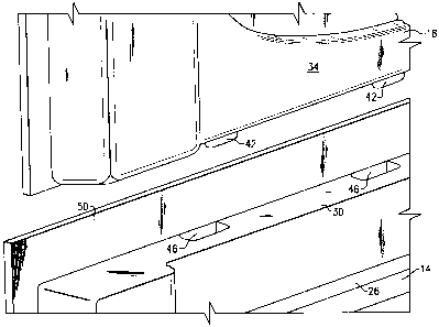
Figure 2 illustrates a close up view of one of the surround wall sections in
an
installed position;
Figure 3 illustrates a front view of the Figure 2 section in an installed
position;
Figure 4A illustrates a sectional view through line IV-IV of Figure 3 when
the panel is in an installed position;
Figure 4B illustrates a sectional view through line IV-IV Figure 3 when the
panel is in an uninstalled position; and
Figure 5 illustrates a sectional view through line V-V of Figure 3.
DETAILED DESCRIPTION OF THE PREFERRED EMBODIMENT
Figure 1 illustrates an example bathing area surround 10 including a tub
basin 14 and a surround wall 18. The tub basin includes a tub bottom 22, tub
sides
26, and a tub ledge 30. The bathing area surround 10 is shown in an installed
position on the tub ledge 30. The surround wall 18 includes multiple surround
wall
sections, such as a surround wall back 34 and sides 38. In this example, the
tub
basin 14, the surround wall back 34, and the surround walls sides 38 are each
separate pieces that are attached together to form the bathing area surround
10.
Figure 2 illustrates the surround wall back 34 in an unassembled position.
The surround wall back 34 includes a tongue 42 for receipt within a groove 46
defined by the tub ledge 30. A tub flange 50 extends from the tub ledge 30
along the
rear of the surround wall back 34.
2

CA 02643284 2008-11-07
The tub basin 14 and the surround wall 18 are formed from vacuum formed
polystyrene panels, for example. Vacuum forming also forms the tongue 42 and
the
groove 46, which secures the surround wall 18 relative the tub basin 14.
Accordingly, the features for securing the surround wall 18 near the tub basin
14 can
be made entirely with vacuum forming operations. In some examples, a water jet
cutter shapes the perimeter of the tub basin 14 and the surround wall 18 after
vacuum forming the individual panels. The water jet cutter may help shape the
tongue 42 and cutouts or other details within the bathing surround 10.
Referring now to Figure 3, in the installed position, the surround wall back
34 contacts the tub basin 14 at the tub ledge 30 when the tongue 42 is
received with
in the groove 46. The tongue 42 extends into the groove 46 beyond the tub
ledge 30.
As shown in Figure 4A, the tongue 42 helps bias portions of the surround wall
back
34 toward the tub flange 50. More specifically, moving the tongue 42 to the
installed position within the groove 46 tends to move the tongue 42 away from
the
tub side 26 in direction X as the tongue 42 slides down a surface 52 defining
a
portion of the groove 46. The surface 52 angles away from the tub basin 14 to
direct
the tongue 42 away from the tub basin 14.
The tongue 42 also helps bias portions of the surround wall 18 against a
bathroom wall 44. The tongue 42 pulls portions of the surround wall 18 toward
the
bathroom wall 44 as the tongue 42 moves down the surface 52. As known, the
bathroom wall 44 may include studs that are covered by the surround wall 18.
Figure 4B shows the tongue 42 prior to moving to the installed position of
Figure 4A. As shown, the tongue 42 is aligned relative an axis Y defined
generally
by the surround wall back 34 in an uninstalled position, but flexes away from
the
axis Y when moving toward an installed position. In another example, the
tongue
42 is transverse the axis Y when in the uninstalled position, but moves toward
the
axis Y as the tongue 42 slides down the surface 52 to the installed position.
Referring now to Figure 5, moving the tongue 42 away from the tub side 26
moves a surround flange 54 formed with the surround wall back 34 closer to the
tub
flange 50. Moving the surround flange 54 toward the tub flange 50 beneficially
helps seal an interface 58 of the surround wall back 34 and the tub ledge 30.
In
some examples, an installer may run a bead of caulk along the interface 58.
The
3

CA 02643284 2008-11-07
installer may use mechanical fasteners, such as nails or screws, to hold the
surround
wall 18 position against the tub ledge 30, but generally no fasteners are
needed to
hold the surround flange 54 against the tub flange 50. The mechanical
fasteners are
also located apart from the interface 58 near the upper portions of the
surround wall
18 away from the tub basin 14.
The surround wall sides 38 install to the tub ledge 30 in a similar manner.
Although shown as the tongue 42 formed with the surround wall back 34, those
skilled in the art and having the benefit of this disclosure will understand
that other
examples may include the surround wall back 34 including the groove 46 and the
tongue 42 extending from the tub ledge 30.
Although a preferred embodiment of this invention has been disclosed, a
worker of ordinary skill in this art would recognize that certain
modifications would
come within the scope of this invention. For that reason, the following claims
should be studied to determine the true scope and content of this invention.
4

Representative Drawing
A single figure which represents the drawing illustrating the invention.
Administrative Status

2024-08-01:As part of the Next Generation Patents (NGP) transition, the Canadian Patents Database (CPD) now contains a more detailed Event History, which replicates the Event Log of our new back-office solution.

Please note that "Inactive:" events refers to events no longer in use in our new back-office solution.

For a clearer understanding of the status of the application/patent presented on this page, the site Disclaimer , as well as the definitions for Patent , Event History , Maintenance Fee  and Payment History  should be consulted.

Event History

Description Date
Maintenance Fee Payment Determined Compliant 2024-11-04
Maintenance Request Received 2024-11-04
Common Representative Appointed 2019-10-30
Inactive: Office letter 2014-08-11
Grant by Issuance 2013-06-18
Inactive: Cover page published 2013-06-17
Inactive: Final fee received 2013-04-15
Pre-grant 2013-04-15
Letter Sent 2012-12-17
Notice of Allowance is Issued 2012-12-17
Inactive: Approved for allowance (AFA) 2012-12-14
Amendment Received - Voluntary Amendment 2012-11-13
Inactive: S.30(2) Rules - Examiner requisition 2012-05-24
Letter Sent 2010-07-27
Request for Examination Requirements Determined Compliant 2010-07-21
Request for Examination Received 2010-07-21
All Requirements for Examination Determined Compliant 2010-07-21
Revocation of Agent Requirements Determined Compliant 2010-03-24
Inactive: Office letter 2010-03-24
Revocation of Agent Request 2010-03-05
Revocation of Agent Requirements Determined Compliant 2009-12-22
Inactive: Office letter 2009-12-22
Revocation of Agent Request 2009-12-08
Inactive: Cover page published 2009-07-10
Application Published (Open to Public Inspection) 2009-07-09
Inactive: IPC assigned 2009-05-06
Inactive: First IPC assigned 2009-05-06
Inactive: IPC assigned 2009-05-06
Application Received - Regular National 2008-12-04
Inactive: Filing certificate - No RFE (English) 2008-12-04
Filing Requirements Determined Compliant 2008-12-04

Abandonment History

There is no abandonment history.

Maintenance Fee

The last payment was received on 2012-10-30

Note : If the full payment has not been received on or before the date indicated, a further fee may be required which may be one of the following

  • the reinstatement fee;
  • the late payment fee; or
  • additional fee to reverse deemed expiry.

Please refer to the CIPO Patent Fees web page to see all current fee amounts.

Owners on Record

Note: Records showing the ownership history in alphabetical order.

Current Owners on Record
MASCO CORPORATION
Past Owners on Record
PETER DABROWSKI
Past Owners that do not appear in the "Owners on Record" listing will appear in other documentation within the application.
Documents

To view selected files, please enter reCAPTCHA code :


To view images, click a link in the Document Description column. To download the documents, select one or more checkboxes in the first column and then click the "Download Selected in PDF format (Zip Archive)" or the "Download Selected as Single PDF" button.

List of published and non-published patent-specific documents on the CPD .

If you have any difficulty accessing content, you can call the Client Service Centre at 1-866-997-1936 or send them an e-mail at CIPO Client Service Centre.


Document
Description 
Date
(yyyy-mm-dd) 
Number of pages   Size of Image (KB) 
Claims 2008-11-07 3 79
Drawings 2008-11-07 4 78
Description 2008-11-07 4 160
Abstract 2008-11-07 1 12
Representative drawing 2009-06-12 1 15
Cover Page 2009-07-10 2 45
Claims 2012-11-13 3 130
Cover Page 2013-05-29 1 40
Confirmation of electronic submission 2024-11-04 10 177
Filing Certificate (English) 2008-12-04 1 158
Reminder of maintenance fee due 2010-07-08 1 113
Acknowledgement of Request for Examination 2010-07-27 1 178
Commissioner's Notice - Application Found Allowable 2012-12-17 1 163
Notice: Maintenance Fee Reminder 2014-08-11 1 120
Notice: Maintenance Fee Reminder 2015-08-10 1 119
Notice: Maintenance Fee Reminder 2016-08-09 1 120
Notice: Maintenance Fee Reminder 2017-08-08 1 129
Notice: Maintenance Fee Reminder 2018-08-08 1 120
Notice: Maintenance Fee Reminder 2019-08-08 1 120
Correspondence 2009-12-08 3 88
Correspondence 2009-12-22 1 12
Correspondence 2009-12-22 1 30
Correspondence 2010-03-05 3 75
Correspondence 2010-03-24 1 13
Correspondence 2010-03-24 2 31
Correspondence 2013-04-15 1 29
Correspondence 2014-08-11 2 45