Note: Descriptions are shown in the official language in which they were submitted.
CA 02643448 2013-11-28
64053-569
- 1 -
WIRELESS ROOT CANAL APEX LOCATOR
10001.1 (left blank intentionally)
Technical Field
100021 The present invention generally relates to dental apex
locators.
More particularly, the invention is a wireless apex locator that has a data
display unit.
Background of the Invention
100031 Conservative dentistry and oral pathology suggest
therapeutic
treatment of a carious tooth rather than extraction thereof. Consequently, the
endodontic treatment technique of root canal operations involving removal of
the pulp, treatment of the canal and filling thereof, are being carried out
with
increasing frequency.
100041 In performing a root canal operation, it is extremely
important for the
dentist to accurately determine the length of the root canal when removing
pulp therefrom and inserting a filling material therein. For instance, if the
dentist should fail to reach the apex of the root canal, healthy tissue may be
injured or the decayed pulp is allowed to remain which eventually may result
in periodontitis or endodontis.
100051 Generally, the endodontic treatment comprises the steps of
opening
the carious cavity, cutting the enamel caries, removing the coronal pulp,
enlarging the root canal orifice, exploring the root canal, extracting the
radicular pulp, enlarging the root canal, and filling the root canal.
Normally,
numerous probe instruments will be employed to perform this treatment
method, including cleansers, reamers, files, and filling tools. Heretofore,
the
most complex, time-consuming and difficult step in the root canal operation
CA 02643448 2008-08-21
WO 2007/136900
PCT/US2007/062500
- 2 -
has involved determining the depth of penetration of a reamer or file and
precisely controlling and limiting the depth of such reamer or file so as not
to
penetrate either beyond the root apex or short thereof. One previous method
of measuring the root canal length involved the insertion of a thin, flexible
probe or explorer into the canal and performing x-ray of the carious tooth in
order to determine the depth of penetration of the probe into the canal. Once
the accurate measurement had been taken, successively used tools could be
set to the proper penetration depth determined by the dentist.
[0006] Various instruments have been devised in the past for measuring
probe penetration in a root canal, as evidenced by the disclosures of U.S.
Patent Numbers 3,916,529; 3,993,044; 3,753,434; 3,894,532; 3,660,901; and,
3,901,216, however, none of the instruments disclosed by such patents have
been completely satisfactory in indicating the position of the probe relative
to
the canal apex with a high degree of sensitivity and accuracy. In this
respect,
one of the principal problems associated with previous instruments relates to
the fact that the meters used by such instruments for visually indicating the
penetration depth of the probe includes too many graduations to clearly depict
the critical point at which the probe actually reaches the canal apex but does
not penetrate through such apex inadvertently. In order to overcome the
above-discussed deficiency, some prior art instruments have provided means
for actuating an audible or visual alarm, such as a light, when the probe
achieves penetration to a critical point immediately adjacent the apex of the
root canal. This solution is unsatisfactory because the dentist is not
provided
with feedback regarding the rate at which the probe is approaching the apex
of the canal and may result in the probe going beyond such apex in the event
that the dentist's reaction time after actuation of the alarm is not
sufficient to
slow or discontinue insertion of the probe after the latter has reached a
critical
point adjacent the canal apex. Furthermore, the use of audible alarms is
undesirable since sounds produced by such alarms may be difficult to
distinguish in the case of high ambient background noise.
CA 02643448 2013-11-28
64053-569
- 3 -
[0007] Therefore, electronic apex locators have been commercially
introduced. These devices employ an impedance-measuring device that
when connected to the lip of a patient receiving root canal therapy wherein an
endodontic file in the canal of the root provides a signal corresponding to
the
distance of the file from the apex of the root canal. The displayed value of
the
distance to the apex allows the dentist to effectively plan the root canal. A
problem with such electronic apex locators has been the numerous cords or
cables necessary to control the locator, supply the needed power and the like.
A need exists therefore, for a more compact electronic apex locator that does
not require as many such connections or cables.
Summary of the Invention
[0008] The present invention is an electronic apex locator that
has a
wireless connection to a data display unit. The dental apex locator is used to
determine the location of the apex of root in a patient's root canal so that
the
dentist does not penetrate the root. Penetration of the apex can result in
time-
consuming repairs, pain to the patient, infection in certain cases, and in
exceptional cases, loss of the tooth. Unlike prior art locators, the apex
locator
of the present invention does not include wires between the handpiece and a
remotely located display unit.
[0009] The handpiece of the present invention includes an
electronic
module having a battery power source, an impedance analyzer circuit and a
radio frequency transmitter. The handpiece further includes a return or lip
module and a probe module having an endodontic probe.
CA 02643448 2013-11-28
64053-569
- 3a -
[0009a] In one aspect, the present invention relates to a wireless
dental apex
locator for use in determining the location of the apex of a patient's root,
comprising:
(i) an electronic module having a battery power source; an impedance analyzer
circuit
and a radio frequency transmitter; (ii) a return module having a clip for
attachment to
the patient; (iii) a probe module having an endodontic probe with a cable
connected
thereto, wherein the endodontic probe emits a signal; the electronic module,
the
return module and the probe module forming a circuit for the emitted signal
that is
returned to the impedance analyzer circuit through the return module, and
radio
frequency transmitting the signal; (iv) an associated but not physically
connected
display unit having a receiver for receiving radio frequency signals from said
transmitter, the display unit further displaying the received radio frequency
signals on
a graphic display; and (v) a handpiece removably housing the electronic
module,
wherein the probe module is assembled at an end of the handpiece with only the
endodontic probe extending from the handpiece and the able being substantially
internal to the handpiece, and the handpiece further includes a motor for
powering
the endodontic probe and a second DC power source for powering the motor.
[0009b] The endodonic probe, typically a file or cutting tool, is also
used to
measure the distance of travel along the root canal. The probe module is
connected
to the return module. The return module includes a clip for attachment to the
patient,
such as a lip clip. When the return module is attached to the patient,
typically at the
clip, a circuit is completed, thereby explaining the designation of return
module as a
return path for the electrical signal from the probe is provided. The
handpiece
includes a motor for driving the endodontic probe. Because
CA 02643448 2008-08-21
WO 2007/136900
PCT/US2007/062500
- 4 -
the handpiece is battery-powered, the motor is a direct current (DC) motor
and the signal is also a DC signal. No physical ground is provided by the
return module. The signal generated by the probe is a low voltage signal and
is only present when the circuit is energized. The voltage is sufficiently low
that the patient is unaware of its presence.
[0010] The impedance analyzer circuit is used to correlate the distance
that the endodontic probe moves along the root canal. During operation, the
endodontic probe emits an electrical signal, which travels through the
circuit.
The impedance that the signal encounters in traversing the circuit is analyzed
by the impedance analyzer, indicative of location, The RF transmitter in the
handpiece, connected to the impedance analyzer, then transmits a signal via
RF to a display unit which can receive RF signals and display the location of
the probe for viewing by the dental professional.
[0011] Because the handpiece transmits information indicative of the probe
location in the root canal via RF to the display unit, the display unit can be
positioned anywhere in the room and its location will not interfere with the
dentist's movements in performing the operation. The dentist can place the
display unit at any convenient location in the room where he/she can see the
display, which will show the location of the endodontic probe based on the RF
signals transmitted by the handpiece. The display unit is powered, normally
by standard 110 volt alternating current (AC) power, as its power source.
Availability of AC current usually is not a problem in a dental office.
However,
the display unit may be powered by batteries utilizing DC current, if desired,
to
provide further flexibility. Maximum flexibility can be provided by a unit
that
can be powered either by AC or DC current.
[0012] Other features and advantages of the present invention will be
apparent from the following more detailed description of the preferred
embodiment, taken in conjunction with the accompanying drawings which
illustrate, by way of example, the principles of the invention.
CA 02643448 2008-08-21
WO 2007/136900
PCT/US2007/062500
- 5 -
Brief Description of the Drawings
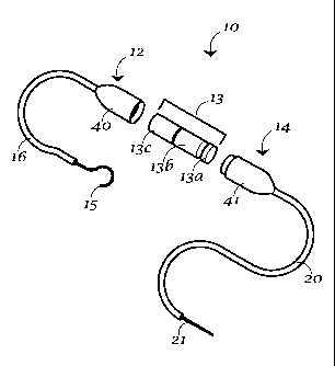
[0013] Figure 1 is
an exploded view of a wireless apex locator according to
the present invention.
[0014] Figure 2 is
a perspective view of a display unit to be used with the
wireless apex locator of Figure 1.
Preferred Embodiments for Carrying Out the Invention
[0015] A wireless
apex locator according to the present invention is
generally designated by the number 10 on the attached drawings. By
"wireless" it is meant that apex locator 10 is not physically connected to its
associated display unit 11, but communicates information to the display by
radio frequency signals as will be more fully discussed herein. The wireless
root canal apex locator of the present invention includes as a system the apex
locator which measures probe position along the root canal and the display
unit that displays the measured probe position for ready viewing by a dental
professional.
[0016] Apex
locator has a lip module 12, an electronic module 13 and a
probe module 14. The modules 12, 13 and 14 are preferably electrically and
removably affixed to one another. By being
removable, the various
components can be serviced or cleaned separately.
[0017] Lip module
12 has a lip clip 15 for physically engaging a patient's
lip. Lip clip 15 is electrically connected to lip module 12 via a suitable
cable
16. When lip clip 15 also is connected to the patient, an electrical circuit
is
formed through lip module 12, electronic module 13, probe module housing,
41, and the probe 21 in a patient's root canal.
CA 02643448 2008-08-21
WO 2007/136900
PCT/US2007/062500
-6-
100181 Electronic
module 13 includes a battery 13a, an impedance
analyzer circuit 13b and a radio frequency transmitter 13c. Probe module 14
includes a probe module housing 41 and an electrical connecting cable 20
affixed to an endodontic probe 21. The electronic module 13 and probe
module 14 can be conveniently assembled as part of a handpiece, the
electronic module 13 and probe module being capable of easy assembly and
disassembly from the handpiece. The handpiece can be ergonomically
designed and further includes a DC motor and a switch, the switch activating
the DC motor. For example, electronic module 13 can be housed within the
handpiece, while the probe module 14 can be assembled at an end of the
handpiece with only probe 21 extending from the handpiece, cable 20 being
substantially internal to the handpiece. The electric motor, when energized by
the switch, activates movement of the probe. The electronic module also
sends an electric signal through the circuit, which signal is analyzed by
impedance analyzer. A suitable filter may be required to filter noise from the
motor so that the electric signal transmitted by probe assembly 41 can be
distinguished from motor noise. Alternatively, the electric signal used to
locate the position of the probe in the root can be sent through the circuit
when the motor is de-energized, so that noise from the motor does not
interfere with the signal indicative of circuit impedance. In this alternate
embodiment, measurement can be conducted accurately when the motor is
de-energized. As the apex is approached, the dental professional may
alternatively energize and de-energize the motor to measure the
professional's approach to the apex.
[0019] Other
arrangements are possible. The electronic module 13 can
be separate from the probe module with a suitable cable connecting the probe
module to the electronic module. The probe module can be housed in an
ergonomically designed handpiece. The probe can be inserted into the root
canal either separately or as an extension from the handpiece. In either
configuration, the probe is connected to the electronic module via cable 20.
CA 02643448 2008-08-21
WO 2007/136900
PCT/US2007/062500
-7-
100201 Battery 13a
is preferably of the rechargeable type, but is not so
limited. Depending on the configuration of the lip module 12, electronic
module 13 and probe module 14, the battery as well as the electronic module
should be removable form the lip module, the probe module and the
handpiece so that it is not sterilized when these parts require sterilization.
Battery 13a may also be replaceable. Impedance analyzer circuit 13b
evaluates the impedance between probe 21 and lip clip 15. Data therefrom is
transferred by means of a suitable radio frequency to display unit 11, where
it
is in turn analyzed and displayed for use by the dental practitioner.
[0021] Lip module
12 preferably has a housing member 40 while probe
module 14 preferably has a complementary housing member 41. Lip module
housing member 40 and probe module housing 41 preferably are configured
so that when they are physically engaged, they form an electronic module
housing for receiving and holding electronic module 13. This conveniently
can be assembled within a handpiece so that cable 16 runs from handpiece to
lip clip 15 and cable 20 at the opposite end of the handpiece is connected to
probe 21. Housing 40 and housing 41 are easily removable from the
handpiece for sterilization.
Alternatively, electronic module 13 is easily
removable from handpiece so that lip module 12, probe module14 and
handpiece can be sterilized as required. The electronic module further
includes an RF transmitter for transmitting signals indicative of the
position.
This assembly will preferably automatically initialize and shut down when
continuity is obtained or removed or will operate only when the circuit is
energized. This conserves battery power.
[0022] Display
unit 11 has a graphic display 31 for representing data
received from probe 21 via electronic module 13. Display unit 11 may also
include appropriate user control interfaces, and also includes a
complementary radio frequency receiver 30 that receives radio frequency
signals from electronic module 13. Display unit 11 can include an electronic
circuit that further conditions the signal and interprets the signal for
display on
CA 02643448 2008-08-21
WO 2007/136900
PCT/US2007/062500
- 8 -
graphic display 31, if sufficient conditioning is not performed by impedance
analyzer circuit 13b.
[0023] In use apex locator 10 with its associated display unit 11 will be
operated as follows:
[0024] a. The dentist will advance an endodontic file 21 toward the apex
of the root canal;
[0025] b. The impedance of the probe module 14 will be determined. The
impedance will either be conditioned and transmitted as a signal to the
display
unit 11 via transmitter 13c to indicate the distance from the apex, or the
impedance measurement will be transmitted as a signal to the display unit 11
via transmitter 13c;
[0026] c. The display unit 11 will condition the impedance as required and
then graphically display the distance to the apex impedance measurement on
graphic display 31 and progression in the canal or the impedance will be
displayed on the graphic display are received from the transmitter; and,
[0027] d. The display unit will optionally provide audible or other signals
to
notify the user of the progression in the canal. In this manner, the apex of a
root canal is effectively located.
[0028] The apex locator as described herein is an advance in the art of
such devices. The invention has been described and shown in the drawings
without attempting to show all of the possible variations that are within the
scope of the invention. The actual scope of the invention will be determined
only by any attached claims.
[0029] While the invention has been described with reference to a
preferred embodiment, it will be understood by those skilled in the art that
various changes may be made and equivalents may be substituted for
elements thereof without departing from the scope of the invention. In
CA 02643448 2008-08-21
WO 2007/136900
PCT/US2007/062500
- 9 -
addition, many modifications may be made to adapt a particular situation or
material to the teachings of the invention without departing from the
essential
scope thereof. Therefore, it is intended that the invention not be limited to
the
particular embodiment disclosed as the best mode contemplated for carrying
out this invention, but that the invention will include all embodiments
falling
within the scope of the appended claims.