Note: Descriptions are shown in the official language in which they were submitted.
CA 02643767 2008-08-26
WO 2007/125407 PCT/IB2007/001132
1
DEVICE AND METHOD FOR CHEMICAL, BIOCHEMICAL,
BIOLOGICAL AND PHYSICAL ANALYSIS, REACTION, ASSAY AND
MORE
FIELD OF THE INVENTION
The present invention relates to a device and a method for carrying out
experin-ients
of chemical, biochemical, biological and physical analysis, reaction and
assay. The
present invention also relates to a device and a method for parallel
processing and
analyzing of chemical, biochemical or biological sample. The present invention
1o further relates to a device and a method used for sampling, transfer,
distribution,
storage, dilution and extraction of chemical, biochemical or biological
sample.
BACKGROUND OF THE INVENTION
Miniaturization is a development tendency of modern analytical science and
technology because for biotech and pharmaceutical industry it means not only
to use
less limited samples, precious chemical compounds and expensive. reagents, but
also to increase sensitivity and to reduce incubation time for some types of
assay
relaying on the ratio of volume to surface area of the reaction well or tube,
such as
Enzyme Linked Immunosorbent Assay (ELISA). But a miniaturized analytical
system
that uses a micro-well plate will arise difficulties and problems for
quantitative liquid
transfer into or from a tiny well even with automations. The existing liquid
handling
techniques of pipetting, piezoelectric droplet dispensing, split pin
dispensing, and
microspritzing can easily cause contamination of neighboring wells and loss of
sample volume resulting from substantial splashing and entrapment of air
bubbles.
High throughput screening assays and techniques of various types are largely
used
for the discovery and development of new therapeutic agents by companies from
small biotech to international pharmaceutical giants. These assays are often
carried
out at a reduced volume in multi-well plates in order to reduce the cost and
save
valuable samples. Currently the 96-, 384-, or 1536-well format multi-well
plates are
CONFIRMATION COPY
CA 02643767 2008-08-26
WO 2007/125407 PCT/IB2007/001132
2
principally used in high throughput screening assays. Because a number of
pipetting
steps are involved in the assay procedure, manually performing high throughput
assay in the 96-well format is already very tedious and can easily introduce
manmade pipetting mistakes. Although automated assay systems may enable to
increase the high-throughput screening capacity of a wide variety of
biochemical and
molecular biology tests such as enzymatic activity, receptor binding,
macromolecular
interactions, protein expression, and protein folding and assembly, but the
extremely
expensive robotic systems may not be affordable for small biotech companies
and is
not worthwhile to buy even for big pharmaceutical companies to carry out oniy
limited
1o screens. So far, there is no dramatic progress for miniaturized assays
needing
separation steps like ELISA.
Multiplexed detection technique is also a trend of the modern analytic
techniques,
which allows simultaneously detecting various analytes from one single sample.
This
technique is particular useful for diagnosis, ciinical study and pathway
identification.
Although protein micro-array technology can meet the multiplexed detection
requirement, some technical difficulties still exist. For example, it is not
designed for
high throughput and manual performance. The reaction conditions for all
analytes are
the same. Furthermore, the extremely high cost for the automation and the
protein
chip will be an insurmountable barrier for it being widely used.
On the eve of worldwide outbreak of bird flu, it urgently needs a cost-
effective, easy-
to-use, robust, rapid, and high throughput micro-assay system capably to test
an
enormous amount of samples by assays like ELISA in order to monitor, prevent
and
control the epidemic situation. Hospital, biotech and pharmaceutical industry,
academic institute and university, agriculture, food and beverage industry
also
welcome such a technology.
CA 02643767 2008-08-26
WO 2007/125407 PCT/IB2007/001132
3
OBJECTS OF THE INVENTION
In view of the disadvantages described above, it is an object of the present
invention
to provide a device and a method for chemical, biochemical, biological and
physical
experiments of analysis, reaction and assay, in a reduced volume.
It is another object of the present invention to provide devices and methods
for the
ease of liquid transfer in or from the reaction chambers quantitatively.
It is still another object of the present invention to provide devices and
methods for
the ease of parallel, quantitative liquid transfer in or out of the reaction
chambers.
It is still another object of the present invention to provide devices and
methods for
io the ease of quantitative sampling of chemical, biochemical or biological
samples.
It is still another object of the present invention to provide devices and
methods for
the ease of quantitative liquid transfer of chemical, biochemical or
biological samples.
It is still another object of the present invention to provide devices and
methods for
quantitative chemical, biochemical or bioiogical sample storage.
It is still another object of the present invention to provide devices and
methods for
the ease of chemical, biochemical or biological sample dilution.
It is still another object of the present invention to provide devices and
methods for
the ease of chemical, biochemical or biological sample extraction.
It is still another object of the present invention to provide devices and
methods for
performing multiplexed detection of chemical, biochemical or biological
samples.
It is still another object of the present invention to provide devices and
methods for
manually high-throughput processing and analyzing of chemical, biochemical or
biological samples with the same or similar accuracy and speed as automation.
SUMMARY OF THE INVENTION
The difficulties in quantitatively transferring small amount of liquid into
and/or out of a
tiny well for an experiment or an application is the bottleneck of further
miniaturizing
analysis, reaction and assay system as well as of further increasing capacity
of high
CA 02643767 2008-08-26
WO 2007/125407 PCT/IB2007/001132
4
throughput. In order to solve this problem, the present invention provides
devices and
methods to ease liquid transfer for a low volume experiment of chemical,
biochemical, biological and physical analysis, reaction and assay. The present
invention also includes devices and methods by which many chemical,
biochemical,
biological, or physical experiments can be implemented in a parallel
processing and
analyzing manner. The present invention further includes devices and methods
for
quantitative sampling, transfer, distribution, storage, dilution and
extraction of
chemical, biochemical or biological samples.
In general, according to the present invention an experiment is performed in a
device
io called reaction unit. In an embodiment the reaction unit comprises a
capillarity
reaction chamber being able to take up liquid quantitatively by itself and/or
to hold
quantitative amount of liquid inside based on capillary action. The reaction
chamber
is in general formed by a reaction unit body and normally has open structure
to allow
liquid and air to pass through during liquid transfer.
When looking at a cross-section of a reaction unit, it is possible to
distinguish a
closed reaction chamber and an opened reaction chamber. The closed reaction
chamber has no additional open structure on its body except of the open
structure for
liquid and air to pass through at both ends whereas the opened reaction
chamber
has at least one additional open structure on, its body. In some embodiments,
the
reaction chamber is open to a non-capillarity zone of the reaction unit, which
does
not permit liquid to remain inside but has open structure at least for air to
pass
through. In still some embodiments, a bottom. structure of the reaction unit
may
attach to the reaction chamber to serve as a channel at least for liquid
passing
through.
Various configurations of the reaction chamber and/or the non-capillarity zone
and/or
the bottom structure in the reaction. unit are suitable for use with the
present
invention. They may run length-wise along their axes at any angles from
parallel to
CA 02643767 2008-08-26
WO 2007/125407 PCT/IB2007/001132
perpendicular with a major axis of the reaction unit. In a preferable
embodiment, all of
them run length-wise along the major axis of the reaction unit.
In an embodiment, a reaction unit has a configuration to allow a light beam to
pass
through the inner space of the reaction unit without objects but the sample.
5 Depending on the field of application, the cross-section of the reaction
chamber, the
non-capillarity zone or the bottom structure may have a cross-section, which
is
circular, triangular, square, rectangular, or a combination therefore. In an
embodiment, a reaction chamber has at least partially a rough surface to
increase
surface area and/or liquid adhesion in order to form a liquid thin layer on
the surface
lo when liquid is emptied from the reaction chamber.
If appropriate the reaction chamber is shaped I has a geometry to increase
light
receiving area, e.g. by a cone shape reaction chamber. The surface geometry
may
be shaped such that optical signals produced from the analytes inside the
reaction
chamber are directed towards an open structure. It is also possible to that
whole or
part of a reaction unit contains a layer of material to which reduces the
optical signal
loss and/or reduce the optical contamination and/or produce evanescence and/or
to
resist chemical interaction and other objectives.
In some embodiments, non-capillarity zone or bottom structure or both can also
serve as a light guiding device to define the light path in the reaction unit.
In an embodiment, geometric forms of a non-capillarity zone can direct coming
light
to the reaction chamber or optical signal from the reaction chamber to a
detector.
In an embodiment, a build-in lens may,be installed on the top of the non-
capillarity
zone with a focus onto the reaction chamber.
In some embodiments, a reaction unit may have more than one capillarity
reaction
chamber.
In an embodiment, whole or part of a reaction unit can be made of any kind
solid
material 'that may or may not allow particular molecules, for example protein,
nucleic
CA 02643767 2008-08-26
WO 2007/125407 PCT/IB2007/001132
6
acid, and lipid, or biological agents, like virus, micro-organisms, and cell,
or small
manmade particles to bind onto reaction chamber surface. Alternative, at least
part of
reaction chamber surface is physically or chemically treated to be able or
unable to
absorb particular molecules or biological agents or small manmade particles.
In an embodiment, a reaction chamber contains porous material inside for
example a
gel, a bead, sintered glass, or particulate matter for particular molecules or
biological
agents.
In an embodiment, the reaction chamber comprises at least one electrode in any
forms.
1o In an embodiment, the reaction chamber comprises at least one build-in
optical fiber.
In an embodiment, the reaction chamber comprises at least one build-in micro
ultrasound device.
In an embodiment, the reaction chamber comprises at least one build-in sensor
of
any kind.
A method for handling of liquids with a reaction unit according to the
i.nvention in an
experiment or an application comprises, but is not limited to, the following
process
steps:
In an embodiment, quantitative full loading is carried out by contacting of
the bottom
open structure of the reaction unit with liquid to draw the liquid into the
reaction
chamber.
In an embodiment, a mechanical vibration process is applied during the
quantitative
full loading.
in an embodiment, quantitative partial loading is also possible by contacting
of the
open structure with a desired amount of liquid on a non-wetting surface, which
is not
enough to fully fill up the reaction chamber.
CA 02643767 2008-08-26
WO 2007/125407 PCT/IB2007/001132
7
In an embodiment, several quantitative loadings are also possible by repeating
the
above quantitative partial loading procedure when total amount of liquid does
not
exceed the volume of the reaction chamber.
Alternatively, quantitative full or partial loading can be carried out by
pipetting desired
amount of liquid into the non-capillarity zone or by pipetting directly into
the reaction
chamber.
In an embodiment, total amount of liquid in the reaction chamber can be
emptied by
using capillary action in which the open structure of the reaction unit
contacts dry or
wet material(s) having much stronger capillary action than the reaction
chamber for
io the liquid (e.g. in case of aquatic solution filter paper can be used) to
draw the liquid
out, by using air pressure to force the liquid to the non-capillarity zone and
sucking
off using a device for example pipette, by using vacuum, by using
centrifugation or by
using air flow or pressure to directly drive the liquid out.
In an embodiment, quantitative partial amount of liquid can be removed from
the
reaction unit by forcing the liquid to the non-capillarity zone and sucking
off desired
amount from the non-capillarity zone or directly suck off from the reaction
chamber
by a liquid transfer device for example pipette.
In another embodiment, quantitative partial amount of liquid can be removed
from the
reaction unit by transferring liquid onto a wettable surface through spotting.
In an embodiment, to replace first liquid totally and quantitatively one can
add second
liquid to the non-capillarity zone with one or several volume of the reaction
chamber
when the bottom opening of the reaction unit contacts the surface of the
second
liquid,. The second liquid will push the first liquid out off reaction chamber
to replace
the old one.
In an embodiment, to replace first liquid partially and quantitatively one can
add
second liquid in a desired volume to the non-capillarity zone when the bottom
CA 02643767 2008-08-26
WO 2007/125407 PCT/IB2007/001132
8
opening of the reaction unit contacts the surface of the first liquid. The
second liquid
will push the first liquid out off reaction chamber in the same amount.
In an embodiment, mixing of liquid in the reaction chamber one can apply an
oscillation of air pressure through the open structure of the reaction unit.
The
oscillation of air pressure shall force the liquid vibration in the reaction
unit. For
example the liquid first moves towards the non-capillarity zone and then moves
back
to its original position.
In another embodiment, a certain frequency of mechanical or sound wave can be
used to mix the liquid.
1o In still another embodiment, a reaction unit containing build-in electrodes
or build-in
micro ultrasound device can be used to force molecules moving in the reaction
chamber in order to mix the liquid.
A. Multi-unit plate
According to the invention, a device for carrying out experiments in parallel,
the multi-
unit plate or strip comprises a plurality of reaction units as described which
are
incorporated or attached to a plate body. In general the reaction units are at
least
partially protruding from the piate body. Preferably, the major axis of each
reaction
unit is perpendicular to the planner of the plate body. The multi-unit plate
is adapted,
in a format of e.g. 2, ..., 96, 384, 1536 or more, for use in conjunction with
a reservoir
plate for example a conventional 96-well format plate and waste pad for liquid
transfer. In an embodiment, the multi-unit plate may comprise a stand, e.g. in
the
form of sidewalls or other means. The stand may have guiding structure
matching the
structure on the reservoir plate and the waster pad to align the multi-unit
plate in only
one orientation for non-error liquid transfer. In some embodiments, the
reaction unit
and the plate body have matched structure to enable the reaction unit to be
attached
onto and/or detached from the plate body.
CA 02643767 2008-08-26
WO 2007/125407 PCT/IB2007/001132
9
B. Reservoir plate
According to the invention, a device said reservoir plate, used in conjunction
with the
multi-unit plate for liquid transfer, comprises a single well or a plurality
of smaller
wells or grooves that are within plate body. There may be guiding structure at
the
edge of the plate matching the structure on the multi-unit plate to allow each
reaction
unit goes into the well or groove to transfer liquid in only one orientation.
C. Waster pad
If appropriate a waster pad to be used in conjunction with a reaction unit,.
resp. a
multi-unit plate is foreseen to remove liquid from at least one reaction
chamber. The
io waster pad comprises at least one layer of liquid absorbing material, which
provides
a higher capillary effect then the reaction chambers; thereby it becomes
possible to
remove the liquid. The base may have guiding structure at the edge of its body
matchin'g the structure on the multi-unit plate for each reaction unit
contacting the
pad in one orientation.
D. Liquid transfer guider
If appropriate a liquid transfer guider is foreseen to facilitate the liquid
transferring
from a reservoir plate to a multi-unit plate or from a multi-unit piate to a
waster pad
and to eliminate orientation mistake as well as to prevent reaction units from
damage. It comprises in general a base having a housing structure to hold a
2o reservoir plate or a waster pad and an upper multi-unit plate holder that
can move
down along supporters fastened on the base. The holder has an opening to
permit
the bottom of each reaction unit on the multi-unit plate to contact a solution
in a well
of the reservoir plate or the absorbing layer of the waster pad when it moves
towards
the base.
E. Low volume full spectrum cuvette adaptor
According to an embodiment of the invention, a low volume full spectrum
cuvette
adaptor is provided to hold and position a reaction unit in a light path of a
spectrophotometer in order to allow light beam to pass through the reaction
unit. '
CA 02643767 2008-08-26
WO 2007/125407 PCT/IB2007/001132
BRIEF DESCRIPTION OF THE DRAWINGS
The herein described invention will be more fully understood from the detailed
5 description given herein below and the accompanying drawings, which should
not be
considered limiting to the invention described in the appended claims.
Fig.1 is an illustration of a reaction unit and a method of its use;
Fig. 2 indicates a perspective view of a reaction chamber;
Fig. 3 is a perspective view of a reaction chamber having a U-shaped non-
10 capillarity zone;
Fig. 4 is a top view a reaction chamber having a U-shaped non-capillarity
zone;
Fig. 5 is a cross-cut view a reaction chamber having a U-shaped non-
capillarity
zone;
Fig. 6- is a perspective view of a reaction unit having an opened reaction
chamber;
Fig. 7 is a perspective view of a reaction unit having a closed reaction
chamber;
Fig. 8 is a perspective view of a reaction unit having a cone shape reaction
chamber;
Fig. 9 is a perspective view of a reaction unit having a U-shaped reaction
chamber;
Fig. 10 is a perspective view of a reaction unit containing a build-in lens;
Fig. 11 is a top view of a reaction unit containing a build-in lens;
Fig. 12 is a cross-cut view of a reaction unit containing a build-in lens;
Fig. 13 is an illustration of a reaction unit for multiplexed detection with
cross-section
view of two examples;
Fig. 14 shows a self-transfer-in low volume manual pipette;
Fig. 15 is a perspective view of a multi-unit plate;
Fig. 16 is a top view of a multi-unit plate;
Fig. 17 is a cross-cut view of a multi-unit plate;
CA 02643767 2008-08-26
WO 2007/125407 PCT/IB2007/001132
11
Fig 18 shows an illustration of a liquid transfer array having piston-and-
cylinder
system;
Fig 19 is an illustration of a liquid transfer array having a membrane-based
system;
Fig 20 is an illustration of a reservoir plate with groove well in column
format;
Fig 21 is top views of reservoir plates with groove in row and grid format;
Fig 22 is an illustration of a waster pad;
Fig 23 is a top view of a washing plate with reservoir grooves and waster pad
strips;
Fig 24 is an illustration of a liquid transfer guider;
Fig 25 is an illustration of a low volume full spectrum cuvette adaptor and a
cuvette.
DESCRIPTION OF THE EMBODIMENTS
According to the invention, a reaction unit I is a device used for carrying
out an
experiment or an application such as analysis, reaction, assay, sampling,
transfer,
distribution, storage, dilution and/or extraction.
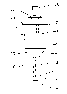
Figure 1 shows an embodiment of a reaction unit and its use. The reaction unit
I
shown here is a tubular device comprising an upper part of a non-capillarity
zone 2
and a lower part of a closed capillarity reaction chamber 3. Both run length-
wise
along a major axis 4 of the reaction unit 1. The reaction chamber 3 is
designed so as
to have the radius enabling it.to use capillary action to draw in enough
amount of
liquid to fill up a space with a volume no less than that of the lower part 3
of the
reaction unit. In an embodiment the radius in the range of 0.005 mm to 1.5 mm.
Other dimensions may be appropriate.
But the radius for the non-capillarity zone 2 will not have capillarity or may
have weak
capillarity but not strong enough to against the gravity to keep liquid in the
non-
capillarity zone 2. Alternatively, the non-capillarity zone may be derived
from a
portion of reaction chamber through chemical treatment. In such a design, only
CA 02643767 2008-08-26
WO 2007/125407 PCT/IB2007/001132
12
amount of liquid equaling to a volume of reaction chamber or the lower part of
the
reaction unit can the reaction unit take up by itself under the capillary
action. A
sample solution can enter through a bottom opening 5 once the bottom open
structure contacts with the solution and meanwhile the air will go out of the
reaction
unit through the upper opening 6. The solution will stop flowing in when it
reaches to
the non-capillarity zone 2 because the capillary action is not sufficient to
further pull
the liquid in. The reaction unit 1 can then hold the same amount of solution
in the
reaction chamber 3 when the bottom opening 5 leaves a sample solution surface
since the capillarity in the reaction chamber 3 is strong enough to against
the gravity
1o force to pull the liquid away. This capillary action driven liquid loading
provides a
simple, reliable and easy-to-use liquid transfer method.
A detection device e.g. such as a spectrophotometer can be used to measure
analytes in the solution in the reaction chamber 3 through which light 7 from
a light
source 26 which passes in the shown embodiment through a lens 27 and a
aperture
28 and then along the major axis 4 through the reaction unit 1. The
concentration of
the analytes can be derived from the optical density obtained by a detector 8.
In the
shown embodiment a black ring like bottom structure 9 may optionally be
installed as
a light guiding device to block the light passing through the reaction chamber
body
10. Because no other object, but the solution, is in the light path of the
reaction unit,
the device can directly be used as a cuvette for extended spectrum detection
(e.g.
full light spectrum from UV to inferred).
Figure 2 shows the reaction unit 1 of Figure 1 in a perspective view. As it
can be
seen, the reaction unit I comprises a tubular capiiiary zone 3 and adjacent
thereto a
non-capillary zone 2. Between the two zones a transition area 29 is arranged
which
has in the shown embodiment a conical shape. Depending on the field of
application
other shapes are appropriate. As it can be seen the cross-section of the
capillary
zone 3 and the non-capillary zone 2 are both circular. However, in some
embodiments, the cross-section of the reaction chamber 3 may have geometric
CA 02643767 2008-08-26
WO 2007/125407 PCT/IB2007/001132
13
patterns which are different e.g. in order to specifically increase the
surface area in
the chamber, to increase capillary action, to increase total volume, and/or
other
objectives. Depending on the field of application square, round, star-like,
oval or
rectangular cross-sections may provide best results.
Figure 3 shows a further embodiment in a perspective view, Figure 4 shows the
same embodiment in a top view and Figure 5 a cross-cut through along line BB
of
Figure 4. As it best can be seen in Figure 5, the transition area 29, which is
arranged
between the capillary zone 3 and the non-capillary zone 2 is .in general U-
shaped
having an in general horizontal section adjacent to the capillary zone 3.
Thereby it is
io achieved that the liquid does not remain inside the non-capillary zone,
which may
tend to happen with flatter angles.
The dimension of the cross-section from top to bottom may be various according
to
applications. A cone shape reaction chamber 3 for example, as shown in Figure
8 in
an upside down view, has an inner surface 11, for example formed by rotating a
straight line 12 in a desired angle a around the central axis 4, is preferred
in the
detection of fluorescence produced by the analytes 13 bound to the inner
surface 11
of the reaction chamber 3 because the conical surface 11 can receive more
light
compared to a cylinder shape.
Figure 9 indicates an embodiment with an in general U-shaped reaction chamber
3
in an upside-down manner. The inner surface 11 is formed by rotating' a
particular
curve 15 around the central axis 4. This U-shaped design directs more optical
signal
16 (e.g. luminescence or fluorescence), generated by the analytes 14, towards
a,
wider opening 17 of the reaction chamber 3.
It has been observed that the strength of the capillarity of the reaction
chamber, the
dimension of the reaction chamber openings and/or the liquid retention volume
at the
bottom, which is related to the dimension and surface features of the bottom
end,
may have some influence on the surface form (e.g. concave, convex and flat) of
the
interface between the liquid and the air. Different surface forms can be
obtained
CA 02643767 2008-08-26
WO 2007/125407 PCT/IB2007/001132
14
through the change of a single parameter or multi-parameters in order to meet
different needs. For example the dimension of the bottom end is one of the key
factors to determine the retention volume of the liquid: the bigger the
dimension, the
more the retention volume. It is possible to change the retention volume by
varying
the dimension of the bottom opening and/or the thickness of the reaction
chamber
body at the end. It has been seen that the liquid surface at the upper opening
of the
reaction chamber is tend to be concave when the bottom opening 1s leaving the
sample solution. If the retention volume at the bottom is less than that
needed to
convert the concave surface into flat or convex surface, the surface at the
upper
1o opening will be concave. Therefore, the desired surface forms can be easily
obtained
by changing these two parameters. For instance, a cone shape reaction chamber
having a smaller bottom opening with gradually reducing the thickness of the
reaction
chamber body at the end will have minimum retention volume and can form a
concave liquid surface at the upper opening which is more suitable for
fluorescence
measurement because the concave liquid surface can serve as a lens to diverge
the
parallel incoming light toward the wall of the reaction chamber. In an
absorbance
measurement a reaction chamber able to generate near flat surface is more
suitable.
In some preferred embodiments, the non-capillarity zone 2 may have cross-
section
geometry of circular, square or rectangular shape with a flat, V- or U-form
bottom or
other combinations. It can also serve as a simple light guiding structure to
block light
passing through the reaction unit body but the reaction chamber. For example a
non-
optical transparent material can be used for making or coating the whole or
part of
the non-capillarity zone body. For some particular applications, an inner
surface 30 of
the non-capillarity zone 2 may have a rotation symmetric cylindrical or a
conical
shape, formed by rotating a desired curve around the central axis 4. Depending
on
the shape, the inner surface 30 may function as a light guiding device to
focus light 7,
coming from a light source 26 (see Figure 1), onto a reaction chamber 3 or
direct
light signal inside a reaction chamber to a detector. Alternatively of in
addition a'
CA 02643767 2008-08-26
WO 2007/125407 PCT/IB2007/001132
build-in lens 19, as schematically shown in Figures 10 to 12, may be arranged
at the
top of the non-capillarity zone 2 as a light guiding device. Figure 10 shows
the
reaction unit I in a perspective manner from above, Figure 11 the reaction
unit 1
according to Figure 10 in a top view and Figure 12 shows a cross-cut along
line AA
5 through the reaction unit according I to Figure 11.
The whole or part of the inner surfaces of the reaction unit I may have a
highly
reflective surface-coating to avoid the loss of the optical signal from
passing through
the body and thus to direct more light to the detector at the opening. For
example as
shown in Figure 9 an outside surface 20 of an optical transparent body 10 may
have
io a layer of silver or an other appropriate material. The optical radiation
16 produced by
analytes 14 in the reaction chamber can finally escape only from the upper
wider
opening 17 and the lower opening 5. A detector (here not shown in detail) can
then
capture the optical signal 16 from these openings. The reflective surface may
also
have a layer of an over-coating for other objects like to protect the
reflective layer, to
15 avoid optical contamination and so on. For example when the surface of the
reaction
chamber has an aluminum layer, an over-layer of other material can avoid the
reagents to directly contact with the aluminum surface.
The surface of the reaction unit may chemically and/or physically be treated
to permit
selective binding of or non-binding of target molecules based on the
particular use or
2o assay procedure (e.g. non-homogeneous assay like ELISA or homogeneous
assay).
By introducing a surface layer of desired materials, the functional domain of
the
molecule in the layer will interact with target molecules through covalent or
non-
covalent bonds like ionic, hydrophobic interaction, or metallic bonds, or will
protect
target molecules from binding. For example, the surface of the reaction
chamber is
coated with a layer of an antibody and the correspondent antigen in the sample
will
bind to the antibody and remains on the surface after removal of the sample
solution
from the reaction chamber. In various embodiments, preferably, the outside
surface
of the reaction unit or part of it may chemically be treated to form a non-
wetting
CA 02643767 2008-08-26
WO 2007/125407 PCT/IB2007/001132
16
surface for avoiding the forming of a fluidic droplet. For example a
hydrophobic
outside surface will be more suitable for a reaction or assay carried out in
an aquatic
solution.
By using a rough surface finishing (not shown in detail), a reaction chamber 3
can
largely increase its surface area so that more target molecules are able to
attach to.
The rough surface finishing of a reaction chamber can also increase liquid
retehtion
and form a liquid thin layer on the surface of the reaction chamber made of
either
hydrophilic or hydrophobic materials. The liquid layer will ease the liquid to
flow into
the reaction chamber especially made of hydrophobic materials and will also
protect
1o bound molecules from drying rapidly.
The reaction unit 1 is in general made out of solid materials such as metal,
glass,
plastic (e.g. polystyrenes, polypropylenes, acrylates or polycarbonate),
rubber or
others. In some applications, the reaction chamber and the non-capillarity
zone can
be made of different materials (any kind of difference e.g. in composition,
structure,
color and so on) or made of one material and treated one of them with another
material because they have different functions and need to meet different
requirements such as the feature of capillarity, chemical resistance and so
on. For
example the whole body of a reaction unit may be made of hydrophobic plastic
and
the surface of the reaction chamber can be coated with a hydrophilic polymer
containing a functional domain to which a protein or oligo nucleotide can
attach.
Conventional technologies for manufacturing the reaction unit iiiclude micro-
machining, electrospark discharge machining (EDM), or chemical etching.
Alternatively, the reaction unit can be cast using a polymer or resin. The
reaction unit
can also be made through assembling different parts together or fusing two
half-
reaction units together. For example, to cast a reaction unit containing a
silver layer
within the body of the reaction chamber, a desired hollow tube with a silver
layer on
its out surface can be immobilized within the casting mold of the reaction
unit. The
chemistry of the hollow tubes and polymer will ideally be chosen such that a
CA 02643767 2008-08-26
WO 2007/125407 PCT/IB2007/001132
17
permanent bond will form between the outside hollow tube and the resin or
polymer
that is cast. The inner surface of the hollow tubes will then make up the
reaction
chamber. In such a way, many different devices such as electrodes, optical
fiber and
so on can easily be incorporated into the reaction unit.
According to different applications of the invention, the reaction unit can
have various
forms combined with additional feature, structure, and device. Figure 13 shows
a
reaction unit I for multiplexed detection in a side view (Figure 13a) and in
top views
(Figures 13b and 13c). The reaction unit 1 comprises several reaction chambers
3,
each containing an antibody 22. The reaction chambers are arranged in general
io parallel to each other. After loading a sample containing multi antigens,
the
antibodies 22 in the reaction chambers will only capture its target antigen
from the
sample solution. With additional reagents, the reaction chambers that contain
their
target antigens can produce optical signal which can be recorded by a device
for
example CCD camera.
Embodiments of a reaction unit I schematically shown in the drawings may
contain
any kind of electrodes (not shown in detail) adapted to the reaction chamber
for
detecting electro-signal related to a chemical reaction, molecule interaction,
cell
activity and so on. For example, it can detect an electrochemical reaction
such as
redox reaction. Such a reaction unit may also be used to force liquid flowing
and
charged molecules moving, to raise temperature, to induce
electrochemiluminescence and so on inside the reaction chamber. For example,
applying an alternating electric field can force charged molecules moving back
and
forth inside the reaction chamber to facilitate molecule diffusion, to speed
up the
reaction or to mix solutions. Electro-osmotic flow phenomenon can also be used
to
mix solution. A micro ultrasound device (not shown in detail) may also be
incorporated into the reaction unit for mixing solution, speeding up reaction,-
raising
temperature and so on. According to an embodiment of the invention, optical
fiber
(not shown in detail) may be incorporated in the reaction chamber for example
to
CA 02643767 2008-08-26
WO 2007/125407 PCT/IB2007/001132
18
generate evanescence that can then excite fluorophor labeled molecules bound
to
the molecule that is immobilized on the optical fiber surface for fluorescence
detection. The optical fibers may also function as an optical guiding device
to direct
light in and/or out of the reaction chamber for the measurement of optical
density,
fluorescence, luminescence and so on. The reaction unit I may be used as a
device
for chromatography, electrophoreses and so on. For example a porous material
may
be filled in the reaction chamber for chromatography and synthesis. In order
to avoid
the loss of the porous material from the bottom opening- of the reaction
chamber, a
bottom structure with tiny hole(s) may be used.
Figure 14 shows a pipette 40 with a reaction unit I according to the invention
in a
perspective manner. The pipette 40 and the reaction unit 1 are shown in a cut
view
such that their inside is visible. The reaction unit 1 can be used for a
liquid transfer
device, for example a low volume pipette, where the reaction unit, as a tip of
the
pipette, can quantitatively take up liquid by itself from a liquid reservoir
using capillary
action and a dispense device can then push the liquid to a receiving
receptacle.
Amount of liquid to be transferred is defined by the volume of the reaction
chamber in
a reaction unit. The pipette 40 comprises: a) a housing 31, a cylinder 32
including
two cylinder ends and open structure 33 (opening), with one end positioned
within
the housing 31 and the other end extending from the housing to form a pipette
tip
2o holder 34, a piston 35 that moves within the cylinder between up-limit and
down-limit,
when the piston located at the up-limit, the inner space of the cylinder is
also
connected to the atmosphere through the open structure 33 on the cylinder,
while the
piston moves down and passes the open structure the air in the inner space of
the
cylinder can only go through the open structure of the pipette tip holder 34
thus to
dispense the liquid in the pipette tip to a receiving receptacle, and a
plunger 36 that
drives the piston; b) a disposable pipette tip (reaction unit) 1 can be
attached to the
end of the tip holder to take up by itself as well as retain the liquid to be
transferred.
This tip can be removed from the tip holder, disposed of, and replaced with a
new tip.
CA 02643767 2008-08-26
WO 2007/125407 PCT/IB2007/001132
19
The pipette may be configured to transfer liquids by automated or manual
actuation
of the pipette. Automatically operated pipettes may include a motor for
actuating the
plunger to move the piston within the pipette cylinder for liquid transfer.
Manually
operated pipettes require the pipette user to apply force to the plunger head
(38),
usually with a thumb, to actuate the piston.
Since the taking-up volume is solely determined by the tip itself, the liquid
transfer
device does not need a very accurate, expensive, complex and difficultly
manufacturing piston-and-cylinder unit. Besides, the device will be accurate,
need no
calibration, have no manmade transfer volume difference, require less finger
1o movement, have no temperature caused pipetting volume change due to the
warm
hand, and so on. Furthermore, the device can be used for non-volatile fluid as
well as
highly volatile fluid because the air pressure in both sides of the liquid to
be
transferred will always keep the same at the taking-up position. It may not be
necessary to have an open structure on the cylinder wall for non-volatile
fluid
because the tiny amount of fluid taken up by the tip will not build a pressure
inside
cylinder high enough to interfere the tip to take up the fluid quantitatively.
The
existing pipette may also be used as a dispense device.
Because the reaction. unit can take up and hold quantitative amount of liquid,
it can
be used as devices for sampling, transfer, distribution, dilution, extraction,
storage
2o and so on. An opened capillarity reaction chamber as e.g. shown in Figure 6
may be
a preferable device for dilution and extraction because the liquid in the
reaction
chamber can directiy contact with another one through the open structure 23
(gap) in
body 10. To achieve a defined dilution, the quantitative amount of first
solution in the
reaction unit can easily be mixed with a desired volume of second solution in
a well
or tube. For extraction, the two liquids should be insoluble with one another
and the
reaction unit should generate capillarity strong enough to hold one of them in
the
reaction chamber. During extraction, the liquid in the reaction chamber will
stay there
and should not be replaced by another one. For example, a hydrophilic reaction
unit
CA 02643767 2008-08-26
WO 2007/125407 PCT/IB2007/001132
can be used for taking up a hydrophilic sample solution and then can be
immerse
into desired hydrophobic solvent in a container for extraction. A
redistribution of
anaiytes occurs between the two solutions and will finally reach equilibrium.
A closed reaction chamber 3 as schematically shown in Figure 7 is a suitable
device
5 for direct storage of samples. In order to prevent stored frozen sampie
(e.g. biological
sample, compound and so on) from falling off, the reaction chamber can be
designed
so that the bottom has a smaller dimension than the top for example V or U
forms.
Alternatively, a bottom structure with a smaller dimension or different cross-
section
can be used to hold the sample. Further, the bottom structure may be made of a
1o hydrophobic material and is designed to have a dimension of the open
structure big
enough to permit hydrophilic liquid passing through but will avoid the
solution
contacting a bottom sealing membrane because the non-wetting bottom structure
will
not pull the solution to fill up its space due to the surface tension of the
liquid.
A micro sensor may also be adapted to the reaction chamber for measuring
15 temperature, pH, target molecules, and so on.
With the development of nano-technology, more and more new and useful devices
can also be adapted to this invention.
Multi-unit plate
According to the invention, parallel experiment of any kinds of above
applications
20 may be carried out in a number of reaction units on a multi-unit plate.
Figure 15
shows a perspective view of a multi-unit plate 39 in perspective view, Figure
16 in a
top view and Figure 17 in a cross-cut view along line AA of Figure 17. Several
reaction units I are integrated within a plate body 41. The axis 4 of each
reaction unit
1 is in general perpendicular to the plate body 41. The multi-unit plate is
adapted for
use in conjunction with a reservoir plate, e.g. for example a 96-well format
(not
shown in detail) plate and waste pad for liquid transfer. At the edge of the
plate body,
there may stands protruding (not shown in detail) that are sufficiently high
to avoid
the bottom of the reaction unit to contact a surface on which the multi-unit
plate is
CA 02643767 2008-08-26
WO 2007/125407 PCT/IB2007/001132
21
positioned. The stand may contain guiding structures (not shown in detail)
matching
that on the reservoir plate and the waster pad to align the multi-unit plate
in a desired
orientation with the reservoir plate and the waster pad for non-mistake liquid
transfer.
The multi-unit plate can be made of any solid materials such as metal, plastic
and
glass, without limitation by way of example. A multi-unit plate frame (a multi-
unit plate
without reaction unit) and the reaction unit may be made separately then
assemble
together. Numerals structure can be used to fix the reaction unit in the
opening on
the multi-unit plate frame. For example, in an embodiment, screw and nut
structure is
used and the plate frame serves as a rack for the reaction unit. This
designing may
1o be more suitable for sampling, storage, dilution, transfer and so on. The
multi-unit
plate frame and the reaction unit can also be made in whole by casting. In
some
cases, part of the reaction unit may be made together with a plate body then
assemble together. For example the non-capillarity zone can be made in one
plate
body and the rest part of reaction unit is made together with a multi-unit
plate frame.
Dilution plate
According to the invention, a dilution plate is a particular use of the multi-
unit plate to
make the dilution much easy and fast. In an embodiment dilution units (or
reaction
units) with defined volume can be fastened on a plate body in a desired format
based
on the demands. For example the dilution unit in each column from A to H has a
volume of 1, 2, 3, 4, 5, 6, 7, and 8 micro liters. A grooved reservoir plate
in column
format is used and each sample is loaded in each grooved well. Dilution units
in each
column will take up a serial amount of each sample. The sample can then be
transferred for example by centrifugation to a welled reservoir plate where
wells in
each column from A to H will get 1, 2, 3, 4, 5, 6, 7, and 8 micro liters of
the sample. In
such a way, a serial of dilution of standard and samples in an assay- can be
easily
done in a single step from a standard or samples without many steps of
pipetting.
Liquid transfer array device
CA 02643767 2008-08-26
WO 2007/125407 PCT/IB2007/001132
22
According to an embodiment in Figure 18 of the invention, liquid transfer
array
device comprises: a) a number of cylinders 51 within an array plate body 52
with one
end project from the body to form a holder 53 for a pipette tip; b) a number
of pistons
54 of which one side is fixed on a driving plate body 55 and another side
containing a
slot 56 can move within the cylinder; c) a number of quantitative liquid self-
transfer-in
pipette tips 57 can be attached to the holders. When the driving plate is at
the liquid
taking-up position, the slut of the piston connects inner space of the through-
hole to
the atmosphere so the attached tips can take up quantitative amount of liquid
from a
reservoir by itself without the influence of the air pressure otherwise built
up inside
1o cylinder. The liquid can be dispensed into a receiving receptacle when the
driving
plate pushes the piston further after the slut is within the cylinder.
A membrane-based system that can function as the above piston-and-cylinder
system to produce positive pressure. Figure 19 is an illustration of a liquid
transfer
array device using a positive pressured gas to fulfill the liquid transfer
from the tips to
a receiving multi-well plate. The device comprises an array platen 131 with a
number
of through-holes 132 where the bottom ends form the pipette tip holders 133,
an
elastic membrane 134 attached to the bottom platen 135, containing of openings
136
in same format of the array platen, of a driving force producer with a gas
inlet/outlet
137. When at the taking-up position, the upper through-hole end of the array
platen
2o does not contact the membrane and therefore the through-hole is also open
to the
atmosphere at the upper end. When at the dispensing position illustrated
inside the
cycle, the array platen and the driving force producer are brought
together.and the
membrane in between will tightly contact the upside of the array platen to
seal the
upper ends of the through-holes 132. Pressured gas is then allowed to flow
into the
driving force producer to push the membrane 133 of the openings 136 bowing
towards the through-hole 132 of the array platen to push the liquid out of the
tip 138.
The pressured gas can be obtained by a mean of pressured gas tank or pumps.
This
membrane-based system can also be used directly for expelling of the liquid
from the
CA 02643767 2008-08-26
WO 2007/125407 PCT/IB2007/001132
23
multi-unit plate or dilution plate when they are used as the array platen 131
and the
tips 138.
Reservoir plate
The reservoir plate may have many types like a plurality of wells, grooves,
grid like
grooves or a big flat well. These plates may be fabricated from a variety of
solid
materials of metal, glass, or plastic, without limitation by way of example.
The surface
of the plate may chemically be treated to avoid the binding of the reagents or
to expel
the solution according to the applications. The dimension of the liquid
reservoir plate
will permit the bottom opening of each reaction unit to contact the solution
in the well
1o of the reservoir plate. There may be guide function structure matching the
structure
on the stand of the multi-unit plate for guiding the reaction units go into
the
correspondent locations like wells or grooves.
Wells on the reservoir plate is arranged in a format correspondent to that of
the
reaction unit on the multi-unit plate. The well shall be big enough for the
project part
of the reaction unit to go into it. Therefore, the bottom opening of the
reaction unit
can contact the liquid in the well to take up quantitative amount of liquid
into the
reaction chamber.
The grooved well of the reservoir plate shall have dimension and format that
permit
the bottom opening of reaction unit to contact the liquid in the groove. The
groove
formats and length are designed for different applications in order to reduce
the times
of pipetting. Figure 20 is an embodiment of a grooved reservoir plate in a
full-length
column format. The groove 61 is long enough to permit all reaction units in
one
column of the multi-unit piate to go into the same groove. There is guiding
structure
62 at the edge of plate matching the structure on the stand of the multi-unit
plate for
guiding the reaction units go into the correspondent grooves and the reaction
units in
each column will get the same sample. If a grooved reservoir plate in a.full-
length row
format as shown in Figure 21 is used to introduce different detection reagents
in a
row-wise, the reaction units in each row will receive the same detection
reagent. In
CA 02643767 2008-08-26
WO 2007/125407 PCT/IB2007/001132
24
such a way, one sample can simultaneously be tested by several different
reagents.
The grid like grooved reservoir plate Figure 22 is for a special case of the
grooved
reservoir plate for filling up all reaction units with same solution. Although
it can be
replace by a big flat welled reservoir plate the grid like groove type plate
needs less
solution for performing the liquid transfer.
Waster pad
Figure 22 shows an embodiment of a waster pad, The waster pad comprises a base
71, an absorbing layer 72 having very strong capability to absorb liquid and a
surface
layer 73 that protects the under layer and permits liquid to pass through. The
1o absorbing layer is sat in a space formed by wall like structure 74 on the
base. The
above surface layer is fastened by a frame structure 75. There may be guiding
structure 62 matching the structure on the stand of the multi-unit plate for
guiding the
reaction units to contact the surface layer in a desired orientation.
In other variants the, base may contain draining structure under the absorbing
layer
and an opening to permit connect to a device like vacuum pump to suck the
liquid out
of the absorbing layer for keeping the layer functional when a large amount of
liquid
needs to be removed for example in case of top loading.
Figure 23 indicates an embodiment of a waster pad designed as a plurality of
strip
pads 76 with a groove like reservoir 77 in next to further ease some
procedures for
2o example to repeat washing the reaction chamber. There may be guiding
structures
62 matching the structure on the multi-unit plate for guiding the reaction
units go to
the correspondent locations like grooves or strip pads. Therefore, the filling-
up
reaction chamber and the removal of the washing buffer can be carried out on
the
same plate.
Liquid transfer guider
According to an embodiment of the invention, the liquid transfer guider in
Figure 24
comprises a base 81 having three-side wall structure 82 to house a reservoir
plate or
CA 02643767 2008-08-26
WO 2007/125407 PCT/IB2007/001132
a waster pad on the base and an upper multi-unit plate holder 83 that can move
down, guided by holes 84, along supporters 85 fastened on the base 81. The
multi-
unit plate holder 83 contains a groove structure 86 permitting a muiti-unit
plate to
slide in and out along the groove structure. An opening structure 87 of the
multi-unit
5 plate holder allows the bottom of each reaction unit on the multi-unit plate
to contact
the solution in the well of the reservoir plate or the absorbing layer of the
waster pad
when it moves down towards the base. Spring structure 88 is installed between
the
base and the holder having two functions. One is to protect the holder from
moving
too close to the base resulting damage of the multi-unit plate and another is
to push
io the holder back to its home position so that the reservoir plate or waster
pad can be
slide in and out of the base.
Low volume full spectrum cuvette adaptor
According to an embodiment of the invention, a low volume full spectrum
cuvette
adaptor 91 as shown in Figure 25 can be used in conjunction with a capillary
cuvette
15 92 or a reaction unit as an ultra-micro cuvette of a conventional
spectrophotometer.
The adaptor comprises a V groove 93 and a lever 94 with a spring 95 in a
through
channel 96. A position-body 97 of capillary cuvette can be fixed in the
channel
through the V groove and the lever. Thus the capillary tube 98 is positioned
so that
when the adaptor is put into the cuvette holder of a spectrophotometer the
light will
20 go length-wise through the capillary tube from one end to another. The
length of light
path can be varied by changing the length of the capillary or controlling the
loading
volume of sample. The capillary cuvette is suitable for full spectrum
detection
because it is open at both ends.
B. - Methods of use
25 According to the invention, the methods for carrying out experiment
comprise: a)
providing a device said a reaction unit adapted to take up by itself into,
through the
bottom open structure, and hold in the reaction chamber quantitative amount of
liquid
under capillary action as described above; b) quantitatively transferring into
and/or
CA 02643767 2008-08-26
WO 2007/125407 PCT/IB2007/001132
26
out of the reaction chamber with sample, reagents, buffers and so on; c)
detecting
signal of spectroscopy, optical density, fluorescence, luminescence, electric
potential,
electrical conductivity, pH, temperature, and so on. Based on the different
application, some steps may need repeat once or several times.
To transfer quantitative amount of liquid into or from a reaction unit can be
carried out
with the methods as the follows.
For quantitative full loading of the reaction chamber one can simply lower
down the
reaction unit till the bottom open structure (9) under the surface of the
liquid. The
liquid will spontaneously flow into the reaction chamber (3) under the
capillary action
io and will cease flowing once the front of the liquid reaches at a position
between the
reaction chamber and the non-capillarity zone (2) because the dimension and/or
geometry and/or surface character of the reaction chamber and the non-
capillarity
zone are different enough for capillarity to fade away. The amount of the
liquid flow
into the reaction unit is equal to the volume of the reaction chamber and this
amount
of liquid will contained in the reaction chamber when the bottom open
structure
leaves off the surface of the liquid.
It has been observed that the surface of a reaction chamber may need to be pre-
wetted by liquid to form a thin layer of liquid in order to fully load the
reaction
chamber depending on dimension, geometry, surface character and material of
the
2o reaction chamber. Introducing a mechanical vibration process during the
loading of
liquid can overcome partially filling the reaction chamber. For example,
sometime a
reaction chamber made of hydrophobic materials e.g. polystyrene cannot be
filled up
fully because of incompletely pre-wetted. Therefore the mechanical vibration
can be
used to force the liquid to flow into the reaction chamber and to wet the
surface it
passes through. The liquid will finally fill the reaction chamber due to the
capillary
force. The mechanical vibration process may also be critical for fully loading
a totally
dried reaction chamber made of hydrophilic materials such as glass in a
limited time.
CA 02643767 2008-08-26
WO 2007/125407 PCT/IB2007/001132
27
Quantitative partial loading is performed by contacting of the bottom open
structure to
a desired amount of liquid on a non-wetting surface or well, which is not
enough to
fully fill up the reaction chamber. Further, several quantitative partial
loadings can be
done by repeating the above quantitative partial loading procedure when total
amount of liquid does not exceed the volume of the reaction chamber.
Alternatively, addition of the quantitative amount liquid to the non-
capillarity zone (top
loading) or reaction chamber can also be used for a full and partial loading.
Furthermore, the reaction chamber may contain dried reagents. So the reaction
can
start right after a sample introducing into the reaction chamber without many
partial
io loading steps.
Total amount of liquid in the reaction chamber can be empted by the capillary
action
through the direct touching of the open structure (9) of the reaction unit to
a surface
of dry or wet absorbing material(s) having much stronger capillarity than the
reaction
chamber for example filter paper for aquatic solution. Alternatively, the
liquid can be
removed through changing the air pressure to force the liquid into the non-
capillarity
zone and sucking off by a device for example pipette. Vacuum, centrifugation
or
pressured air can also drive the liquid out of the reaction unit.
Quantitative partial amount of liquid can be removed from the reaction unit
through
air pressure change to force the liquid into the non-capillarity zone and
sucking off
the desired amount from the reservoir or directly suck off the quantitative
amount
from the reaction chamber by a liquid transfer device for example pipette.
Alternatively, quantitative amount liquid can be removed from the reaction
unit by
transferring liquid onto a wettable surface through spotting. By selecting
desired
wettability of surface material, one can control the transfer amount for each
spotting.
It is possible to replace first liquid totally and quantitatively by second
liquid. One can
add second liquid to the non-capillarity zone (2) with at least one volume of
the
reaction chamber when the bottom opening (5) of the reaction unit contacts the
CA 02643767 2008-08-26
WO 2007/125407 PCT/IB2007/001132
28
surface of the second liquid. The second liquid will push the first liquid out
off reaction
chamber to replace the old one.
To replace first liquid partially and quantitatively one can add second liquid
in a
desired volume to the non-capillarity zone when the bottom opening of the
reaction
unit contacts the surface of the first liquid. The second liquid will push the
first liquid
out off reaction chamber in the same amount.
In order to mix the liquid in the reaction chamber one can apply an
oscillation of air
pressure on the open structure of the reaction unit. The oscillation of air
pressure
shall force the liquid vibration in the reaction unit. For exampie the liquid
first moves
1o towards the non-capillarity zone and then moves back to its original
position.
Alternatively, an alternating electric field can also be applied to force
molecules
moving back and forth in the reaction unit containing electrodes for the
mixing of the
liquid. A reaction unit containing a micro ultrasound device can aiso be used
to mix
the liquid. Further, a mechanical vibration mixer or sound wave producer can
be used
for the above purpose as well.
A number of detection devices (e.g. spectrophotometer, fluorometric
spectrophotometer, CCD camera, electric meter and so on) can be used for
recording the signal in the reaction chamber. The build-in devices like
electrodes,
optical fiber and so on may ease of the signal detection.
In another embodiment, the methods for carrying out high throughput experiment
comprise: a) providing a multi-unit plate having multiple reaction units
adapted to
take up by themselves into through the bottom open structure and hold in the
reaction chamber quantitative amount of liquid under capillary action as
described
above; b) quantitatively transferring into and/or out of the reaction chamber
with
sample, reagents, buffers and so on with other devices such as liquid
reservoir
plates, waster pad and optionally liquid transfer guider; c) detecting signal
of
spectroscopy, optical density, fluorescence, luminescence, electric potential;
CA 02643767 2008-08-26
WO 2007/125407 PCT/IB2007/001132
29
electrical conductivity, pH, temperature, and so on. Based on the different
application, some steps may need repeat once or several times.
With the help of the guiding structure on the sidewall stand between the multi-
unit
plate and liquid reservoir plates or waster pad or using liquid transfer
guider if no
such structure available, it can be very easy with capillary action to load of
liquid into
the reaction units in a correct orientation by dipping the reaction units to
their
correspondent wells or grooves of liquid reservoir plates or to remove the
liquid from
the reaction units by contacting of the bottoms of the reaction units with the
surface
of the waster pad. Repeating the above procedures or several partial loadings,
samples and different reagents can easily be introduced quantitatively into
the
reaction units for the reaction, analysis or assay.
The groove plates are preferred for a multiplexed detection with several
samples. For
example each grooved well in column format plate contains a sample from each
patient while each grooved well in row format plate has reagents for each
particular
analyte. Therefore, the reaction units in each column will be loaded with same
sample and then the samples can react with each particular reagent in a row-
wise. In
such a way, each sample can obtain several results simultaneously.
A plate reader, CCD camera or many other detection devices can be used to read
the signal from the multi-unit plate.
In a further embodiment, the methods for carrying out sampling, transfer,
dilution,
extraction and storage comprise: a) providing a device having one or multiple
reaction unit(s) adapted to take up by itself/themselves into through the
bottom open
structure and hold in the reaction chamber(s) quantitative amount of liquid
under
capillary action as described above; b) quantitatively taking up liquid sample
into the
reaction chamber optionally with other devices such as liquid reservoir plates
and
liquid transfer guider; c) dispensing or introducing onto a surface or a
membrane or
into a well plate for liquid transfer or for dilution.
CA 02643767 2008-08-26
WO 2007/125407 PCT/IB2007/001132
Because the reaction unit is also a quantitative capillarity liquid handling
device, it
makes sampling, transfer, dilution and storage much easier due to the features
and
diverse variations of the reaction unit and liquid reservoir plates. For
example taking-
up quantitative amount of sample can simply be done by dipping the reaction
unit
5 open structure into the sample. The sample can then dispense onto a surface
by
direct contact or introduce into a well by centrifugation for dilution or
storage or other
purpose. With an open reaction chamber, it may just need to stir the reaction
unit in
the well for the dilution or for extraction. The reaction unit may also be
used directly
for storage of a sample, optionally with sealing membrane or caps.
1o C. -Potential Applications
The invention, according to an embodiment, provides a parallel and/or multiple
experiment platform for high throughput that can be used for low volume assays
to
ease liquid transfer procedure through capillary action and facilitate the
reaction and
may be employed for experiments of biological, biochemical, chemical or
physical
15 analysis, reaction and assay. It also provides devices and methods for
sampling,
storage, transfer, extraction and dilution of biological, biochemical or
chemical
samples.
Although there are numerous of analysis, reactions and assays, they can
basically be
divided into two types: homogeneous and heterogeneous. The homogeneous one
20 can be carried out in the reaction unit just by taking up solution of
reaction
component sequentially or premixed. The heterogeneous one involves reaction
components in different phase. For example in a solid-phase assay one of the
reaction components may be immobilized on the surface of the reaction chamber.
The immobilized reaction component usually interacts with other target
components
25 in the reaction solution. Signals will be generated by some reaction
components if
they present together in the reaction chamber and then can be detected by one
of
detection methods known in the art. The opened reaction unit is favorable to
some
heterogeneous reactions in which the two phases are for example liquid and
liquid or
CA 02643767 2008-08-26
WO 2007/125407 PCT/IB2007/001132
31
liquid and gas because the reagents in the opened reaction chamber have more
surface area to contact other reagents in another phase.
One can use the multi-unit plate to perform immunoassays. For example in
ELISA, a
protein sample is loaded into the reaction unit. An over-night 4 C or a few
hours 37 C
incubation will allow the protein to immobilize to the surface of the reaction
chamber
through physical interaction. Alternatively, the protein can be immobilized
through a
chemical reaction such as hydroxysuccinimide groups, which bind amine moieties
on
protein. After removal of the non-bound protein by several washes a miik
powder
solution for example is used to block the area where can further absorb
protein. An
io enzyme labeled detection antibody then replace the milk powder solution and
it will
bind to the target protein on the surface of the reaction chamber. A substrate
solution
will be loaded for color development by the bound enzyme labeled detection
antibody
after completely removal of the free one by several washes of the reaction
chamber.
A micro-well plate reader reads the optical density at the wavelength with a
maximum
absorption of the substrate or product.
The sandwiched ELISA with electrochemiluminescence technology can also be
performed in reaction units containing electrodes of which the working
electrodes are
coated with streptavidin. An analyte in a sample is sandwiched between
biotinylated
capture antibody and ruthenylated detecting antibody by consequently loading
and
2o removal of correspondent reagents or sample and washing in between. With
the
application of electrical potential in the presence of tripropylamine (TPA),
the
immuno-complex bound to streptavidin will generate electrochemiluminescence
signal that can be captured by photomultiplier tubes (PMT's) reader.
Fluorescence polarization (FP) is a well-known technique for the study of
biological
interactions and is frequently used in the high-throughput screening (HTS) of
potential new drug targets. It can be easily adapted to the multi=unit plate
for
performing the screening. For example, the FP assays can be performed in the
reaction units using CyDye-labeled ligands to compete for the receptors with
testing
CA 02643767 2008-08-26
WO 2007/125407 PCT/IB2007/001132
32
compounds. Upon the binding of CyDye-Iabeled ligands to the receptors, the PF
value increases because of the slower rotation of the receptors. When the
testing
compound is able to bind to the receptor at the same binding site of the CyDye-
labeled ligand, it will compete for the site with the CyDye-labeled ligand and
causes
the PF value decreasing due to less CyDye-labeled ligand and the receptors
complex
formed. Therefore, after loading of CyDye-labeled ligand, receptor and testing
compounds to the multi-unit plate, the PL value in each reaction unit of the
plate
measured by using a fluorescence polarization reader reflects the binding
capacity of
the testing compound to the receptor.
1o It is also an ideal device for synthesis of tiny amount of peptides or
oligo-nucleotides
with solid-phase synthesis approach, because the synthesis contains multiple
loading, emptying and washing steps. By defining the loading sequence of
desired
reagents through the conjunction with reservoir plates, one can easily control
the
length and sequence of peptide or oligo-nucleotide in each addressed reaction
unit.
Alternatively, tiny beads may be introduced into the reaction chamber to
provide
more surface area for the synthesis.
Because of easy liquid handling, the device can be used for a solid phase
enzymatic
assay for compound screening in order to eliminate interference of colored
compounds on the results, which is frequently encountered. The procedures of
the
solid phase enzymatic assay are 1) to immobilize the enzyme to the surface of
the
reaction chambers through physical interaction or chemical reaction, 2) to
wash away
un-bound enzyme, 3) to introduce compounds into the reaction chambers and to
form enzyme-compound complexes, 4) to wash away free compounds, 5) to load
substrate into reaction chambers for reaction and 6) to analyze the enzyme
activity
by use a device such as micro-well reader. When a compound is able to bind to
enzyme and inhibit the enzyme, the enzyme activity will decrease.
The device can also be used for compound screening using a mass spectroscopy
approach. The procedure are 1) to immobilize target protein to the surface of
the
CA 02643767 2008-08-26
WO 2007/125407 PCT/IB2007/001132
33
reaction chambers through physical interaction or chemical reaction, 2).to
wash away
un-bound protein, 3) to introduce compounds into the reaction chambers and to
form
protein-compound complexes, 4) to wash away free compounds, 5) to free the
compound from protein-compound complexes through chemical or physical
treatment, 6) to analyze the freed compound by mass spectroscopic methods.
The top loading feature of the device can also be used for automation to
simplify the
procedure such as washing step in which same solution need to be transferred
in
and out of the device several times. Instead of bottom touch loading, a liquid
handling
device for example a multi-channel tubing pump can continuously introduce
washing
io buffer into the non-capillarity zone to wash away unbound analytes or
compounds
from the device by several volume of washing buffer flowing through the
capillarity
reaction chamber.
The present invention has been described - using detailed descriptions of
embodiments thereof that are provided by way of example and are not intended
to
limit the scope of the invention. The described embodiments comprise different
features, not all of which 'are required in all embodiments of the invention.
Some
embodiments of the present invention utilize only some of the features or
possible
combinations of the features. Variations of embodiments of the present
invention that
are described and embodiments of the present invention comprising different
combinations of features noted in the described embodiments will occur to
persons of
the art. The usefulness should not be limited by these examples and
embodiments
but should include the following claims as well.
Although the present invention has been described in relation to particular
embodiments thereof, many other variations and modifications and other uses
will
become apparent to those skilled in the art. It is preferred, therefore, that
the present
invention be limited not by the specific disclosure herein, but only by the
appended
claims.