Note: Descriptions are shown in the official language in which they were submitted.
CA 02645605 2008-09-15
1
PCT/EP2007/001451
Frame construction for a switchgear cabinet, switchgear cabinet and construc-
tion kit for the switchgear cabinet.
The invention relates to a frame construction for a switchgear cabinet with
frame profiles and connecting elements, wherein the frame profiles are connec-
io ted and/or connectable via the connecting elements in order to form a
frame
construction together, wherein at least one of the frame profiles is formed in
the cross-sectional view, as an L-profile with one first and one second leg
sec-
tion, said second leg section arranged in an L-shape thereto, and the leg sec-
tions delimit an inner sector together, wherein the first leg section passes
into a
front-side section which is angled towards the inner sector and the first
front-
side section passes into a first end-section which is angled towards the first
leg
section and wherein the second leg section passes into a second front-side
section which is angled towards the inner sector, and the second front-side
section passes into the second end-section, which is angled towards the
zo second leg section, wherein at the first front-side section and in
longitudinal
direction of the L-profile, first through openings are arranged in a fixed
spacing,
as well as a switchgear cabinet and a construction kit for such switchgear cab-
inet.
Switchgear cabinets, especially low-voltage switchgear cabinets are used in
numerous plants, for example as electricity supply for large facilities or for
pro-
duction machines. The switchgear cabinets are typically set up specifically
for
the respective purpose of use. However to simplify the planning and design of
switchgear cabinets and to keep a particular modularity so they can be expan-
ded later on or to enable the modernisation of the switchgear cabinets,
switchgear cabinets usually consist of a frame construction with mechanical in-
terfaces, where the respective, necessary electric functional modules are at-
tached to. Typically the frame constructions are enclosed by cover elements or
mounted doors.
CA 02645605 2013-12-12
Such a frame construction is offered by the company Logstrup in Kvistgard,
Denmark. Components of
this frame construction are, in the cross-sectional view, L-shaped profiles
having a plurality of angles,
which profiles are screwed together with corner mounting pieces_ The L-shaped
profiles comprise
numerous mounting openings, which are sometimes formed as mounting holes and
sometimes mounting
slots. Typically the electric functional modules are fixed to this frame
construction via adapter elements.
It is therefore the object of the invention to suggest a simplified frame
construction which allows a
simplified project planning and assembly of switchgear cabinets. This object
is solved by a frame
construction, switchgear cabinet or a construction kit for a switchgear
cabinet having the features
disclosed herein.
The frame construction according to the invention is suitable and/or formed
for a switchgear cabinet,
especially for a low-voltage and/or medium-voltage switchgear cabinet. It is
preferred to operate currents
up to 3.000 A, especially up to 5.000 A or up to 10_000 A, arid/or voltages up
to I kV, especially up to
20kV or 30 kV in the switchgear cabinet_ In particular voltages over 250 V
and/or currents over 150 A are
operated. Preferably the switchgear cabinets, which are built in the frame
construction, comply with the
test requirements according to IEC 60439-1, EN 60439-1 or DIN EN 60439 Part 1
in the respective valid
version and/or the corresponding subsequent conditions.
The frame construction comprises frame profiles, which are connected and/or
connectable by connecting
elements in order to form the frame construction. Particularly, the frame
profiles are cut-off to the length
necessary for the frame construction and/or are ready to mount. The length of
the frame profiles is
preferably an integral multiple of the fixed/non-variable spacing. Preferably
the connection between the
frame profile and the connecting elements is formed as form-closed/positive
and/or frictional fit
connection, especially as screw coupling, wherein the connecting elements and
the frame profiles can
preferably be separated without being destroyed.
=
=
= =
CA 02645605 2008-09-15
3
At least one of the frame profiles is formed as an L-profile with first and
second
leg sections, arranged to each other in an L-shape, wherein the cross-section
is
preferably defined as a plane perpendicular to the longitudinal direction of
the
L-profile and wherein between the leg sections an inner sector/area is
defined.
Viewed further in the cross-sectional view, the first leg section goes into an
angled first front-side section, wherein the first front-side section is
angled to-
wards the inner section and/or towards the second leg section, especially slop-
ing. Thus the front-side section is especially angled in and/or towards the
area
enclosed by both leg sections. The first front-side section passes into a
first
io angled end-section, wherein the first end section is angled towards the
first leg
section and/or into the direction of the leg section and especially sloping.
The
first leg section, the first front-side section and the first end section
together
form a common, especially U-formed shape. At the second leg section, ana-
logue to this, a second front side section as well as a second end section at-
tach.
At the first front-side section and in longitudinal direction of the L-profile
first
through openings are provided, that are arranged in a fixed spacing, thus hav-
ing a fixed constant distance and are sequenced especially in a straight line.
According to the invention second through openings are arranged at the first
end section and in longitudinal direction of the L-profile in the same fixed
spa-
cing, thus especially sequenced along a straight line. Preferably the first
and
second through holes are arranged at the same height along the longitudinal
direction of the L-profile.
It is an underlying idea of the invention, that with help of this
modification,
mechanical interfaces are provided in a frame construction, which allow the in-
tegration of electric functional modules, especially fused load connecting
blocks, without any and/or with few adapters, from the most important manu-
facturers. At the same time, the L-profiles according to the invention offer
great
mechanical stability.
In a preferred embodiment of the invention at the second front-side section
and/or at the second end-section, third and where required fourth through
CA 02645605 2008-09-15
4
openings are arranged in longitudinal direction of the L-profile in the fixed
spa-
cing. With this embodiment, the L-profile offers a further mechanical
interface.
Optionally, the L-profile comprises fifth through openings, which are located
in
the first and second leg sections, respectively, wherein the fifth through
holes
are arranged opposite and/or in alignment to the second and fourth through
holes, respectively. Further optional sixth through openings are provided,
which are located in the first and second leg sections, respectively, wherein
the
sixth through holes are arranged opposite and/or in alignment to the third and
io first through holes, respectively.
The fifth through holes allow for example the mounting of covers/blinds or
door elements and can also be used as guiding and/or fixture of pin elements
with or without screw-in threads, which engage and are screwed in, respect-
ively, with one pin end into one of the fifth or sixth through openings and
with
the other pin end in an opposite through opening. These pin elements are for
example used for fixing the connecting elements. Instead of pin elements it is
also possible to use other fastening elements, which can engage into opposite
and/or aligned through openings.
In a preferred embodiment of the invention, the first and section leg sections
are connected/joined to each other and in the cross-sectional view arranged at
right angles to each other. In is particularly advantageous, if in addition,
the leg
sections are arranged parallel to the associated end-sections, respectively,
and/or the front-side sections are arranged perpendicular to the associated
leg
sections and/or end-sections, respectively. Preferably the L-profile, in the
cross-
sectional view, comprises an axial-symmetrical design, wherein the axis/plane
of symmetry is formed as bisecting line between both leg sections. It is
further
preferred that the first, second, third, fourth, fifth and/or sixth through
openings
are distributed axial-symmetrically as well.
In an ideal production design the L-profile is formed in one piece and prefer-
ably made from a galvanised and/or aluminium or zinc coated steel plate or
stainless steel plates, preferably with a thickness or approximately 2 mm.
CA 02645605 2008-09-15
It is advantageous, if the length of the leg section, front-side section
and/or
end-section or -sections are an integral multiple of the fixed grid spacing.
With
this embodiment the external dimensions of the L-profile are also compatible
to the fixed grid spacing which is already used with the spacing of the
through
5 holes in longitudinal direction.
With an optional development of the invention, a respective one of the first,
second, third, fourth, fifth and/or sixth through openings of the L-shaped
profile
is arranged in one plane, especially of a cutting/sectional plane,
perpendicular
io to the longitudinal direction of the L- profile in a grid with a fixed
spacing. This
further development underlines the inventive idea to create with the frame con-
struction a three dimensional grid of through openings as a mechanical inter-
face. With this development, the through holes are not only spaced apart in
the
longitudinal axis of the L-profile with the fixed grid spacing, but are also
ar-
ranged perpendicular to the longitudinal direction of the L-profile in a
corres-
ponding grid. Preferably the distance of the through holes to each other
relates
to the middle of the openings of the respective through holes on the top
and/or
outer side of the L-profile. Preferably at least 50%, preferably more than
70%,
especially more than 90% of all through openings are arranged in the profiles
n in the grid.
In an advantageous realisation of the frame construction, the fixed spacing is
12.5 mm. The spacing thus covers the spacing of 25mm typical for switchgear
units and also take into consideration the fact that electrical functional
modules
can be mounted shifted by half of the fixed spacing. This realisation bases on
the consideration that there are different manufacturer norms regarding grid
spacings, which are not compatible with the use of a typical grid spacing of
25mm, but rather lead to gaps between the electrical functional modules from
different manufacturers. Further preferred are through openings as circular
openings, especially formed with a diameter of approx. 5mm, especially
5.2mm.
It is preferred to use a mounting block as a connecting element between two L-
shaped profiles, which preferably comprises at two side faces L-shaped
parts/raised contours, which during assembly will be at least partly encom-
CA 02645605 2013-12-12
passed in a form fit. A more practical design is there, when on three side
faces an L-shaped part/raised
contour is provided, as the mounting block is usable as a corner element In a
further development of the
mounting block, the L-shaped. contours are interrupted, to provide a
possibility for receiving other
profiles, especially C-profiles, especially in a form fit.
For assembly it is practical if the mounting block has on at least two side
faces, especially three side
faces, especially in the middle or near the middle a respective thread for
receiving a fixing screw_ The
depth direction of the screw thread is preferably perpendicular to the
respective side face and/or aligned
so that the fixing screw is parallel to the longitudinal direction of the L-
profile to be fixed. Especially
advantageous is if the dimensions of the mounting block are also matched to
the fixed grid spacing and/or
the external measurements of the mounting block are formed without
parts/raised contours as an integral
multiple of the grid spacing.
In addition to this the frame construction can include a clamping element,
which can be fixed to the L-
profile and which works together with the mounting block to fix the mounting
block and the L-profile.
Especially the clamping element is formed as the pin element or mounting
element mentioned above or
supports thereon_
The frame construction according to the invention can optionally include
further frame profiles, such as a
C-profile, a U-profile and/or an L-profile. However these profiles have one
thing in conunon, that they
comprise through holes, which are spaced apart in longitudinal direction of
the profiles in the fixed
spacing and/or are arranged in a plane perpendicular to the longitudinal
direction of the profiles in a grid
with the fixed spacing.
With the design of the frame construction, the L-profiles are preferably used
as corner pillars and/or as
frame profiles of the ceiling frame and/or floor frame_
The underlying problem of the invention is also solved with a switchgear
cabinet or a construction kit for
switchgear cabinet comprising a frame construction as disclosed herein. The
construction kit includes ¨
as already described ¨ L-profiles and connecting elements, especially mounting
=
6
CA 02645605 2008-09-15
7
blocks, as well as, optionally, C-profiles, U-profiles and/or L-profiles as de-
scribed above.
Both with the frame construction and with the switchgear cabinet, most of the
mentioned embodiments provide the additional advantage that their external
dimensions (WxDxH) can be chosen in the fixed spacing. In this way with the
preferred embodiments not only the center of the holes of the through open-
ings but also for example the external corners of the switchgear cabinet are
ar-
ranged in the grid with the fixed spacing. Besides the spacing requirement the
io free choice of the external dimensions is attained by the fact that the
profiles
after cutting to length are already ready to mount. Especially there is no
further
necessity to provide additional mechanical interfaces i.e. by re-shaping, for
connecting to the mounting blocks.
Further features, details, advantages, combinations and effects based on this
invention can be found in the following embodiments.
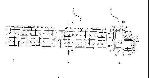
Figure 1 shows a first embodiment of a frame construction according to the
invention;
Figure 2a,b,c, shows detailed views of the frame construction in figure 1;
Figure 3 shows an L-profile in figure 1 in planview and sectional view;
Figure 4 shows a corner portion of the frame construction in figure 1;
Figure 5 shows a mounting block from the corner portion in figure 4;
Figure 6 shows a clamping place from the corner portion in figure 4;
Figure 7 shows a C-profile in figure 1 in planview and sectional view;
Figure 8 shows a U-profile in figure 1 in planview and sectional view;
CA 02645605 2008-09-15
8
Figure 9 shows a second embodiment of a frame construction according to
the invention;
Figure 10 shows the frame construction in figure 9 in planview with mounted
fused load connecting block of a first embodiment;
Figure 11 shows the frame construction in figure 9 in planview with mounted
fused load connecting block in a second embodiment;
io Figure 12 shows an alternative mounting block i.e. for the corner
portions in
figure 4;
Figure 13 shows the alternative mounting block of the figure in the mounted
state.
Like same reference numerals in the figures denote the same or corresponding
elements.
Figure 1 shows a first embodiment for a frame construction 1 of a switchgear
cabinet with the dimensions (WxDxH) of 600mm x 600mm x 2000mm in
schematic threedimensional view tilted from above.
The rectangular frame construction 1 comprises a floor frame 2 and a ceiling
frame 3, which are connected together via four corner pillars 4 and an interme-
diate pillar 5.
The floor frame 2 and the ceiling frame 3, respectively, are formed by four
con-
necting profiles 6, which are connected via mounting blocks 7 in such a way
that the four connecting profiles 6 of the floor frame 2 and the ceiling frame
3,
respectively, make up a rectangle. In the corners of the rectangle, the
mounting
blocks 7 are arranged, wherein the mounting blocks 7 of the floor frame 2 are
connected via the corner pillars 4 with the mounting blocks 7 of the ceiling
frame 3..
CA 02645605 2008-09-15
9
Both the connecting profiles 6 of the floor frame 2 and the ceiling frame 3 as
well as the corner pillars 4 are formed as L-profiles identical in
construction. In
this way the connecting profiles 6 and the corner pillars 4 can be cut off
from
the same semi-finished L-profile.
Figure 3 shows such a L-profile 8 as it will be used as a connecting profile 6
and/or corner pillar 4 in the frame construction in Figure 1, on the left side
in
schematic planview, and on the right side in a schematic sectional view, in a
sectional plane, perpendicular to the longitudinal direction of the L-profile
8,
like for example along the cutting plane III-Ill. The L-profile 8 is formed as
a
one-piece, bent steel profile. As can best be seen in the sectional view, the
L-
profile 8 comprises a first and second leg section 9 and 10, respectively,
which
are arranged perpendicular to each other in an L-form and together enclose or
delimit an inner sector A.
Attaching to the first leg section 9, is a first front-side section 11, which
starting
from the longitudinal direction of the first leg section 9 in direction of the
second leg section 10 is bent at right-angles and runs parallel, especially
partly
congruent with it. Attaching to the front side section 11 is a first end
section 12,
which starting from the longitudinal direction of the first front side section
ills
bent towards the first leg section 9 at right angles and runs parallel,
especially
partly congruent with it. Together the first leg section 9, the first front
side sec-
tion 11 and the first end section 12 form a U-shape.
In the same way, attaching to the second leg section 10 is a second front side
section 13 and a second end-section 14 so that the L-profile 8, in the
sectional
view, is formed axialsymmetrical to an axis of symmetry, which, in the section-
al plane, runs as bisecting line between the first and second leg sections 9
and
10.
The lengths of the different sections 9 to 14 of the L-profile 8 are formed,
so
that the corner points (or corner areas) a,b,c,d,e between the sections 9 to
14
are arranged in an equal grid with a fixed spacing of 12.5mm. In particular
all
sections 9, 10, 11, and 13, which are formed as intermediate sections, have
CA 02645605 2008-09-15
lengths which are an integral multiple of the fixed spacing. The front-side
sec-
tions 11 and 13 are formed having half the length of the leg sections 9 and
10.
In the end sections 12 and 14 and in the front-side sections 11 and 13 respect-
ive circular through holes 15 a, b and 16 a, b, respectively, are formed with
a
5 diameter of 5.1mm. Optionally, opposite to and/or in true alignment to
the
through holes 15a, b in the end sections 12 and 14, further through holes 17a,
b
are placed in the first or second leg sections 9 and 10, respectively. It is
further
optional that through holes 18b are formed in the second leg section 10 oppos-
ite to the through holes 16a in the front-side section 11 as well as through
holes
10 18a are formed into the first leg section 9 opposite to and/or in true
alignment
to the through holes 16b in the second front-side section 13.
As can be seen best from the sectional view, a respective through hole 15 a, b
to 18 a, b lies in a common sectional plane. The through holes 15 a, b to 18
a,b,
especially the centre of those holes on the exterior side of the profile 8, on
one
cutting plane, are arranged in a grid with fixed spacing of 12.5mm and particu-
larly in the same grid as the corner points a, b, c, d, e. As can be seen from
the
planview on the left side of figure 3, planes having a respective group of
through holes 15 a,b to 18 a, b are arranged equidistantly with a spacing of
12.5mm in longitudinal direction of the L-profile 8. In this way there is not
only
a two dimensional grid in the sectional plane, but also the through openings
and/or the corner points are arranged in a three-dimensional grid with the
grid
spacing of 12.5 mm. As a preferred alternative design an L-profile 8 can be
seen, which comprises a through hole 15a, b to 17a,b in every plane and only
in the first and last plane possesses a through hole 18a, b.
Figure 4 shows the corner connection of 3 L-profiles 8 with one mounting block
7 as it is used for example in frame construction 1. The three L-profiles 8
are ar-
ranged at right angles to each other, the corner area of the corner connection
will be constructed using the mounting block 7 and in such a way that the ex-
terior sides of the first and second leg sections of the L-profiles 8,
respectively,
form a common plane with the respective exterior side of the mounting block
7.
CA 02645605 2008-09-15
11
For a better understanding of the construction of the corner connection, it is
referenced to figures 5 and 6, which show the mounting block 7 and a clamp-
ing plate 19, respectively. The mounting block 7 is a cube with an edge
length,
which is an integral multiple of the spacing and in this example is 50 mm. On
three contact sides 20a,b,c of the cube, L-shaped parts/raised contours
21a,b,c
are provided, which are matched in their dimensions to the L-shaped profile 8,
so that the parts/raised contours 21a,b,c can be used as assembly help and
form closure. Just off centre of each contact side 20a,b,c is a thread bore
22a,b,c to receive fixing screws. The direction of depth of the thread bores
is
aligned perpendicular to the respective contact sides 20a,b,c and/or to the op-
posite exterior sides. The three exterior sides of the mounting block 7, that
are
facing away and therefore not visible, are formed substantially flat.
The clamping plate 19 in figure 6 is formed as L-shaped plate with a through
opening. During the assembly, as is shown in figure 4, a clamping plate 19
will
be inserted into each L-profile 8 and secured with a pin (not shown) or the
like
against a movement towards the mounting block 7 in a form closure. Instead of
a pin, it is also possible to insert a screw e.g. with a thread length of
25mm.
The assembly screws will be slid through the through opening of the clamping
zo plate 19 and screwed into the thread bores 22a,b,c, wherein the clamping
plates 19 and thus the respective L-profiles 8 are pulled against the mounting
block 7 and finally fixed.
In figure 1 it can be seen, that the whole external skeleton of the frame con-
struction 1, especially each edge section, is made up from the described L-
shaped profiles 8. The intermediate strut 5 however is realized as a C-profile
23
as shown in figure 7.
In figure 7, the C-profile 23 is shown in the same view as the L-profile 8 in
fig-
ure 3. The sectional view along the sectional line VII-VII discloses that the
C-
profile 23 comprises a base section 24, to which on both sides a respective
front-side section 25 a and b, respectively, and in the further progression,
an
end-section 26 a and b, respectively, attach, wherein these sections analogue
to the sections 11 to 14 of the L-profile 8 are arranged and/or formed at
right
angles to each other. The C-profile 23 especially comprises through openings
CA 02645605 2008-09-15
12
as well, which are arranged in a grid with a spacing of 12.5mm, and/or corner
points or areas, which are arranged in the same grid spacing. The through
openings are arranged analogue to the L-profile along the longitudinal
direction
of the C-profile in planes, which are spaced apart from each other in the spa-
cing of 12.5 mm. The C-profile 23 thus supplements a construction kit consist-
ing of L-profiles 8 and connecting elements, especially mounting blocks 7,
with
an optional component, which makes the 3-D grid extendable.
In figure 1, an intermediate strut/support 27 is shown on the front side of
the
io frame construction, which consists of an U-profile 28 which is shown in
figure
8. The U-profile 28 comprises a base section 29 to which at both ends end sec-
tions 30 a and b, respectively, attach at right-angles. Analogue to the L-
profile 8
and the C-profile 23, the U-profile 28 also comprises through holes and/or
corner points or areas, which are arranged in a grid with the spacing 12.5mm.
Also the planes, in which the through openings are organized, are spaced apart
from each other in the spacing. Thus the U-profile 28 forms a further optional
component in the construction kit described above.
The figures 2 a, b, c show enlarged detailed views A, B and C from below and
illustrate the connection of different profiles with the help of connecting
plates
and corners as further connecting elements. Preferably the through openings in
these connecting elements are also formed in the grid with fixed spacing of
12.5 mm.
Figure 9 shows a second embodiment of a frame construction 1 with the di-
mensions (WxDxH) of 1000mm x 600 mm x 2000mm, using the same compon-
ents of the construction kit 1 in figure 1, especially in different lengths
and thus
illustrating the numerous possibilities of use of these components. As an ex-
ample, two safety/fused connecting blocks 31 and 32 are mounted in the frame
construction 1. From the figure it is visible, that by the different
components of
the construction kit, a frame construction 1 is made, which provides a continu-
ous grid spanning over several components, with a fixed spacing of through
holes, as mechanical interfaces. Through this three dimensional grid of
through
holes it is possible to mount the safety/fused connecting blocks 31 and 32
without any additional and/or frame construction specific adapter elements.
CA 02645605 2008-09-15
13
Figures 10 and 11 show a respective frame construction, which is similar or
identical to the frame construction 1 in figure 9 in a planview. Figure 10
illus-
trates the installation of a safety/fused connecting block 33 from the ABB
slim-
line series, which is fixed to the corner pillar 5 (from the L-profile 8), the
inter-
mediate pillar 4 (from the C-profile 23) as well as to the intermediate
struts/sup-
ports 27 (from the U-profile) with a respective screw connection and no ad-
apter.
io Figure 11 shows the same frame construction as in figure 10, wherein a
safety/fused connecting block 34 from the company "Jean Muller" is mounted.
The safety/fused connecting block 34 is also mounted without any additional
adapter material.
The dimensions, especially the given lengths and spacing of the embodiment
relate to especially advantageous embodiments, but the possibility to use
other
dimensions is also part of this disclosure.
Figure 12 shows a different mounting block 7 with an edge length of 50mm in
two different three-dimensional schematic views. In contrast to the mounting
block 7 in figure 5, the mounting block 7 in figure 12 is formed by an Alumini-
um die casting method. The functional elements such as the contact sides
20a,b,c, the L-shaped parts/raised contours 21a,b,c as well as the threaded
holes 22a,b,c are also existent in the mounting block 7 in figure 12, but in a
form, which has been adapted to the manufacturing procedure for example by
using oblique edges. In contrast to the mounting block 7 in figure 5, the
mount-
ing block 7 in figure 12 has L-shaped forms 21a,b,c, which have been interrup-
ted twice. The interruptions in the shown embodiment are realized such that
the L-shaped forms 21 a, b, c are made up of three especially right-angled par-
tial areas which protrude from the side areas of the contact sides 20 a, b, c.
With other mounting blocks constructed differently, the double interruptions
can be realized differently.
As can been seen best from figure 13, the double interruption allows the
mounting block 7 to receive C-profiles 23, wherein the C-profiles 23 encompass
CA 02645605 2008-09-15
14
two of the three rectangular partial areas in a form closure. The mounting
block
7 is thus formed as connecting element between the L-profiles and C-profiles
23.
=