Language selection

Search

Patent 2645876 Summary

Third-party information liability

Some of the information on this Web page has been provided by external sources. The Government of Canada is not responsible for the accuracy, reliability or currency of the information supplied by external sources. Users wishing to rely upon this information should consult directly with the source of the information. Content provided by external sources is not subject to official languages, privacy and accessibility requirements.

Claims and Abstract availability

Any discrepancies in the text and image of the Claims and Abstract are due to differing posting times. Text of the Claims and Abstract are posted:

  • At the time the application is open to public inspection;
  • At the time of issue of the patent (grant).
(12) Patent Application: (11) CA 2645876
(54) English Title: RIGID U-SHAPED PACKAGING CONTAINER WITH INTEGRAL HANDLE
(54) French Title: CONTENANT D'EMBALLAGE RIGIDE EN U A POIGNEE SOLIDAIRE
Status: Deemed Abandoned and Beyond the Period of Reinstatement - Pending Response to Notice of Disregarded Communication
Bibliographic Data
(51) International Patent Classification (IPC):
  • B65D 61/00 (2006.01)
  • B65D 81/02 (2006.01)
  • B65D 85/00 (2006.01)
(72) Inventors :
  • O'HARA, JEFFREY (United States of America)
  • ROMETTY, JOHN A. (United States of America)
(73) Owners :
  • ILLINOIS TOOL WORKS INC.
(71) Applicants :
  • ILLINOIS TOOL WORKS INC. (United States of America)
(74) Agent: FINLAYSON & SINGLEHURST
(74) Associate agent:
(45) Issued:
(86) PCT Filing Date: 2007-02-23
(87) Open to Public Inspection: 2007-09-27
Examination requested: 2008-09-16
Availability of licence: N/A
Dedicated to the Public: N/A
(25) Language of filing: English

Patent Cooperation Treaty (PCT): Yes
(86) PCT Filing Number: PCT/US2007/004779
(87) International Publication Number: WO 2007108893
(85) National Entry: 2008-09-16

(30) Application Priority Data:
Application No. Country/Territory Date
11/276,918 (United States of America) 2006-03-17

Abstracts

English Abstract

A packaging container (10) has an integral handle (12). The container is formed from a preformed, rigid unit of generally U-shaped cross-section having a main body portion with a generally flat bottom wall (16) and upstanding, opposing sidewalls (18). The unit is foldable at at least two regions to form a base channel (32) and opposing side channels (34) of a protective package for an item. Hand openings (24) are formed in the bottom wall (16) of the opposing side channels (34) configured for a user to insert a hand for use as the handle (12) for the packaging container.


French Abstract

La présente invention concerne un contenant d'emballage (10) comprenant une poignée solidaire (12). Le contenant est constitué d'un élément rigide préformé à section transversale présentant généralement une forme de U, dont une partie de corps principal présente une paroi inférieure (16) généralement plate et des parois latérales verticales opposées (18). L'élément est pliable au niveau d'au moins deux zones pour former un canal de base (32) et des canaux latéraux (34) opposés d'un emballage protecteur destiné à un article. Des ouvertures (24) pour la main sont formées dans la paroi inférieure (16) des canaux latéraux (34) opposés et permettent à un utilisateur d'y insérer la main afin de disposer d'une poignée (12) pour le contenant d'emballage.

Claims

Note: Claims are shown in the official language in which they were submitted.

CLAIMS
What is claimed is:
1. A packaging container having an integral handle comprising:
a preformed, rigid unit of generally U-shaped cross-section having a main
body portion with a generally flat bottom wall and upstanding, opposing side
walls,
the unit being foldable at at least two regions to form a base channel and
opposing
side channels of a protective package for an associated item, hand openings
formed
in the bottom wall of the opposing side channels configured for a user to
insert a
hand for use as the handle for the packaging container.
2. The packaging container in accordance with claim 1 wherein the unit
is foldable at two regions to define only a base channel and opposing side
walls, and
wherein hand openings are formed in each of the side walls.
3. The packaging container in accordance with claim 1 wherein the hand
openings are formed in the bottom wall only and extend across less than an
entire
width of the bottom wall.
4. The packaging container in accordance with claim 1 wherein the hand
openings are formed as elliptical shaped openings having substantially
straight sides.
5. The packaging container in accordance with claim 1 wherein each of
the opposing side walls includes only one opening.
8

6. The packaging container in accordance with claim 1 including cuts in
the opposing side walls at the foldable regions.
7. The packaging container in accordance with claim 1 including V-
shaped notches in the opposing side walls at the foldable regions.
8. The packaging container in accordance with claim 1 including a
plurality of hand openings formed in each of the opposing side walls.
9. The packaging container in accordance with claim 8 wherein the hand
openings are spaced from one another a predetermined distance.
9

Description

Note: Descriptions are shown in the official language in which they were submitted.


CA 02645876 2008-09-16
WO 2007/108893 PCT/US2007/004779
RIGID U-SHAPED PACKAGING CONTAINER
WITH INTEGRAL HANDLE
BACKGROUND OF THE INVENTION
[0001] The present invention is directed to a packaging container.
More particularly, the present invention pertains to a packaging container
formed
from a rigid U-shaped material having an integral handle.
[0002] U-shaped material or U-board is a known packaging material
for many objects. The material is formed from a layered construction (a
lamination)
of paper and/or paper board that is formed into a U-shape (U-shaped cross-
section).
The board is rigid. That is the walls are rigidly formed into the U-shape
(transverse
relative to the base) and are rigid longitudinally along the length of the
board.
Essentially, the board is rigid, the walls do not fold down onto the base, nor
can it be
folded, length-wise onto itself.
[0003] U-board is used for a wide variety of commonly packaged
items. It can be used to package long, fragile items. In a common use, U-board
is
used for packaging doors and windows to protect the edge of these items from
damage due to bumping, dropping or general handling.
[0004] While U-board has been used with a great deal of success for
packaging such items, in order to carry or otherwise handle the U-board, it
has been
found that handles or grasping members have required additional materials to
supplement the U-board. In large measure handles have been attached to the U-
board to handle or carry the items. Handles that are presently used are made
from
1

CA 02645876 2008-09-16
WO 2007/108893 PCT/US2007/004779
paperboard-type materials, wood, metal or some combination of these materials.
The handles can be strapped or taped to the package to affix the handles. The
strapping or taping requires time and materials and at times, although seldom,
the
handles can be pulled from the package and if the package fall, damage can
occur.
100051 Accordingly, there is a need for a handle for U-board
packages. Desirably, such a handle minimizes the amount of additional
materials,
needed to form or create the handle. More desirably, such a handle is readily
made
and usable, and has a high degree of integrity.
BRIEF SUMMARY OF THE INVENTION
[0006] A packaging container having an integral handle is formed
from a preformed, rigid unit of generally U-shaped cross-section having a main
body
portion with a generally flat bottom wall and upstanding, opposing side walls.
The
unit is foldable at at least two regions to form a base channel and opposing
side
channels of a protective package for an associated item, such as a window or a
door.
100071 Hand openings are formed in the bottom wall of the opposing
side channels. The openings are configured for a user to insert a hand for use
as the
handle for the packaging container. The openings are formed in the bottom wall
only and extend across less than an entire width of the bottom wall so as to
not
extend into the side walls. The openings are preferably formed as elliptical
shaped
openings having substantially straight sides.
2

CA 02645876 2008-09-16
WO 2007/108893 PCT/US2007/004779
[0008] A present package is foldable at two regions to define only a
base channel and opposing side walls, and wherein hand openings are formed in
each
of the side walls. Each side walls can include a single opening or multiple
opens.
[00091 The foldable regions are defines by cuts in the side walls. The
cuts can be straight cuts or V-shaped notches formed in the side walls.
100101 These and other features and advantages of the present
invention will be apparent from the following detailed description, in
conjunction
with the appended claims.
BRIEF DESCRIPTION OF THE SEVERAL VIEWS OF THE DRAWINGS
[0011] The benefits and advantages of the present invention will
become more readily apparent to those of ordinary skill in the relevant art
after
reviewing the following detailed description and accompanying drawings,
wherein:
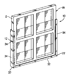
[0012] FIG. 1 is a perspective view of a U-shaped packaging
container with integral handled embodying the principles of the present
invention,
the container shown mounted to a window;
[0013] FIG. 2 is a top view of the container in a flat state, prior to
folding, the container being shown with straight-cut sides;
[0014] FIG. 3 is a side view of the container of FIG. 2;
[0015] FIG. 4 is a cross-sectional view of the container illustrating
the U-shaped cross-section; and
3

CA 02645876 2008-09-16
WO 2007/108893 PCT/US2007/004779
[0016] FIG. 5 is a perspective view of the container shown with
mitered-cut sides, the container being shown with a portion of the side walls
broken
away for ease of illustration.
DETAILED DESCRIPTION OF THE INVENTION
100171 While the present invention is susceptible of embodiment in
various forms, there is shown in the drawings and will hereinafter be
described a
presently preferred embodiment with the understanding that the present
disclosure is
to be considered an exemplification of the invention and is not intended to
limit the
invention to the specific embodiment illustrated.
(0018] It should be further understood that the title of this section of
this specification, namely, "Detailed Description Of The Invention", relates
to a
requirement of the United States Patent Office, and does not imply, nor should
be
inferred to limit the subject matter disclosed herein.
[0019J Referring now to the figures and in particular to FIG. 1, there
is shown a packaging container 10 having an integrated handle 12 embodying the
principles of the present invention. The packaging container 10 is configured
to
support and protect a object,. such as the illustrated window W. The packaging
container 10 is formed from U-board, illustrated generally at 14, and best
seen in
cross-section in FIG. 4, and is a rigid, U-shaped cross-sectional member, much
like a
structural channel member.
100201 For purposes of the present disclosure, the package material,
although defined as having a U-shaped cross-section is, in fact, formed from a
4

CA 02645876 2008-09-16
WO 2007/108893 PCT/US2007/004779
material having a channel-like or squared U-shape having a flat or near-flat
(e.g.,
planar) bottom wall 16 and straight (e.g., generally planar) upstanding side
walls 18.
The corners 20 are typically formed having a radius of curvature (i.e.,
rounded),
however, they may be formed having relatively sharp angles. Nevertheless, for
purposes of the present disclosure, the container material 14 is referred to
as "U-
shaped".
100211 The board 14 is formed in a layered construction (e.g., a
lamination) of paper and/or paper board materials. The board 14 is rigid, and
accordingly, the walls 16, 18 are rigidly formed into the U-shape (transverse
relative
to the bottom wall 16) and are rigid longitudinally along the length 114 of
the board
14. Essentially, the board 14 is rigid, the walls 18 do not fold down onto the
bottom
16, nor can the board 14 be readily folded, length-wise onto itself.
[00221 Accordingly, in order to fold the board 14 about the cross-
section, as seen in FIGS. 3 and 5, cuts are formed by forming straight or
square cuts
22 or miter cuts 122 in the walls 18, as disclosed in Gosis, et al., U.S.
Patent No.
6,896,174, and Loeschen, U.S. Patent No. 6,382,447. The U-board 14 can then be
positioned around the particular item W (as seen in FIG. 1) and the item can
be
wrapped or strapped (as needed) to protect the item W.
[0023] The present invention includes the formation of handles 12
integral with the U-board 14. The handle 12 is formed by cutting an opening 24
into
the bottom wall 16 of the board 14 to define a region for a user to insert a
hand. The
opening 24 can be any of a variety of shapes, however, it is anticipated that
an oval
or elliptical shaped opening, with relatively straight sides 26 and rounded
corners 28

CA 02645876 2008-09-16
WO 2007/108893 PCT/US2007/004779
will be used for its ease in cutting (or forming) in the material 14. However,
other
shapes of openings 24 are also contemplated. Regardless of the shape, the
opening
24 is sized to permit the user to insert a hand (fingers up to about the hand-
finger
joint) into the opening 24 to grasp the board 14 to move or handle the package
W.
[0024] In this manner, because the handle 12 is formed in the board
14 material, it is about as strong as the board 14 material itself.
Advantageously, this
straight-forward solution not only increases assurance of the integrity of the
handle
12 system, it does so while reducing the overall number of parts (e.g.,
handles, etc.)
needed to form a holding element.
100251 It is anticipated that the handle openings 24 can be cut into the
material 14 as the board is cut to fit the item W (e.g., the window or door).
It is also
anticipated that "standard" U-boards 14 can be formed that have a plurality of
openings (the plurality is not shown) formed in the bottom wall 16 at
predetermined
intervals or distances to provide a standardized packaging material for
windows,
doors and the like. It will be appreciated that in use, the board 14 is cut
22, 122 at
the corners 20 and the item W is positioned in the channel 30 in the base
channel
element 32. The side channel elements 34 are folded up along the sides S of
the item
W with the handles 12 disposed in the side channels 34.
[00261 All patents referred to herein, are hereby incorporated herein
by reference, whether or not specifically do so within the text of this
disclosure.
[00271 In the present disclosure, the words "a" or "an" are to be taken
to include both the singular and the plural. Conversely, any reference to
plural items
shall, where appropriate, include the singular.
6

CA 02645876 2008-09-16
WO 2007/108893 PCT/US2007/004779
[0028) From the foregoing it will be observed that numerous
modifications and variations can be effectuated without departing from the
true spirit
and scope of the novel concepts of the present invention. It is to be
understood that
no limitation with respect to the specific embodiments illustrated is intended
or
should be inferred. The disclosure is intended to cover by the appended claims
all
such modifications as fall within the scope of the claims.
7

Representative Drawing
A single figure which represents the drawing illustrating the invention.
Administrative Status

2024-08-01:As part of the Next Generation Patents (NGP) transition, the Canadian Patents Database (CPD) now contains a more detailed Event History, which replicates the Event Log of our new back-office solution.

Please note that "Inactive:" events refers to events no longer in use in our new back-office solution.

For a clearer understanding of the status of the application/patent presented on this page, the site Disclaimer , as well as the definitions for Patent , Event History , Maintenance Fee  and Payment History  should be consulted.

Event History

Description Date
Application Not Reinstated by Deadline 2013-02-25
Time Limit for Reversal Expired 2013-02-25
Inactive: Abandoned - No reply to s.30(2) Rules requisition 2012-07-30
Deemed Abandoned - Failure to Respond to Maintenance Fee Notice 2012-02-23
Inactive: S.30(2) Rules - Examiner requisition 2012-01-30
Amendment Received - Voluntary Amendment 2011-08-30
Inactive: S.30(2) Rules - Examiner requisition 2011-03-28
Amendment Received - Voluntary Amendment 2010-08-20
Inactive: S.30(2) Rules - Examiner requisition 2010-03-12
Inactive: Cover page published 2009-01-21
Letter Sent 2009-01-12
Inactive: Acknowledgment of national entry - RFE 2009-01-12
Inactive: First IPC assigned 2009-01-09
Application Received - PCT 2009-01-08
National Entry Requirements Determined Compliant 2008-09-16
Request for Examination Requirements Determined Compliant 2008-09-16
All Requirements for Examination Determined Compliant 2008-09-16
Application Published (Open to Public Inspection) 2007-09-27

Abandonment History

Abandonment Date Reason Reinstatement Date
2012-02-23

Maintenance Fee

The last payment was received on 2011-02-01

Note : If the full payment has not been received on or before the date indicated, a further fee may be required which may be one of the following

  • the reinstatement fee;
  • the late payment fee; or
  • additional fee to reverse deemed expiry.

Please refer to the CIPO Patent Fees web page to see all current fee amounts.

Fee History

Fee Type Anniversary Year Due Date Paid Date
Request for examination - standard 2008-09-16
Basic national fee - standard 2008-09-16
MF (application, 2nd anniv.) - standard 02 2009-02-23 2009-02-03
MF (application, 3rd anniv.) - standard 03 2010-02-23 2010-02-02
MF (application, 4th anniv.) - standard 04 2011-02-23 2011-02-01
Owners on Record

Note: Records showing the ownership history in alphabetical order.

Current Owners on Record
ILLINOIS TOOL WORKS INC.
Past Owners on Record
JEFFREY O'HARA
JOHN A. ROMETTY
Past Owners that do not appear in the "Owners on Record" listing will appear in other documentation within the application.
Documents

To view selected files, please enter reCAPTCHA code :


To view images, click a link in the Document Description column. To download the documents, select one or more checkboxes in the first column and then click the "Download Selected in PDF format (Zip Archive)" or the "Download Selected as Single PDF" button.

List of published and non-published patent-specific documents on the CPD .

If you have any difficulty accessing content, you can call the Client Service Centre at 1-866-997-1936 or send them an e-mail at CIPO Client Service Centre.


Document
Description 
Date
(yyyy-mm-dd) 
Number of pages   Size of Image (KB) 
Description 2008-09-16 7 222
Representative drawing 2008-09-16 1 13
Drawings 2008-09-16 1 30
Abstract 2008-09-16 2 75
Claims 2008-09-16 2 42
Cover Page 2009-01-21 2 47
Description 2010-08-20 8 229
Claims 2010-08-20 2 45
Description 2011-08-30 8 232
Claims 2011-08-30 1 41
Acknowledgement of Request for Examination 2009-01-12 1 177
Reminder of maintenance fee due 2009-01-12 1 113
Notice of National Entry 2009-01-12 1 203
Courtesy - Abandonment Letter (Maintenance Fee) 2012-04-19 1 174
Courtesy - Abandonment Letter (R30(2)) 2012-10-22 1 165
PCT 2008-09-16 3 88