Note: Descriptions are shown in the official language in which they were submitted.
CA 02646029 2008-12-09
WH 13407CA
TITLE: MEDICATION CASSETTE
FIELD OF THE INVENTION
The present invention relates to packaging for
medication having individual cells for a particular
single medication dosage such as a pill, tablet or
capsule.
BACKGROUND OF THE INVENTION
Blister packaging is one of the more common forms
of medication packaging where individual medication
dosages are retained in individual cells of the blister
pack. The user typically rips the back surface of the
cell to gain access to the particular medication.
A different form of medication packaging involves
individual pill boxes having a series of cells with each
cell having an attached closable lid. These types of
containers are typically used by an end user to organize
the particular medications that are to be taken at
different times each day, and are typically sized for a
week or two week period.
There are also a number of different dispensing
systems that are available for in-home use to assist the
user in the correct dispensing of pills throughout the
day. Some of these systems use a blister packaging
principal, and there are different geometries that are
used for organizing the medications for dispensing.
These systems have not been largely adopted, and are
somewhat difficult to use as the blister pack is
typically designed to provide a tamper proof type
packaging that is manually opened by a user having
sufficient dexterity. Examples of automated systems for
dispensing medication are shown in US Patent 6,848,593
and US Publication 2001/0028308.
- 1 -
CA 02646029 2008-12-09
WH 13407CA
It is also known to have individual pharmacies
organize a user's series of medications such that they
are appropriately packaged for daily intake. This type
of system is helpful if the patient is capable of opening
the package and taking the medication at the appropriate
times.
The present invention provides a medication
cassette that simplifies the packaging of the medication
and can also be used in automated equipment. This
medication cassette can also be used in a manual manner.
The packaging cassette is of a low cost and in a
preferred embodiment is disposable.
SUMMARY OF THE INVENTION
A medication cassette according to the present
invention comprises an outer sleeve releasably receiving
a slidable cartridge having a series of open top cells
for receiving medication. The slidable cartridge
includes opposed ends with each opposed end including a
releasable lock arrangement moveable between a lock
position and a release position. The releasable lock
arrangements in the lock position engage the sleeve at
opposite ends thereof and restrict movement of the
cartridge within the sleeve with the sleeve closing the
open top cells. Each releasable lock arrangement in the
release position allows sliding movement of the cartridge
relative to the sleeve to progressively position the open
top cells beyond the sleeve to allow removal of any
medication within the cells.
According to an aspect of the invention, each
locking arrangement includes a locking member with a
spring bias urging the locking member to a locking
position.
- 2 -
CA 02646029 2008-12-09
WH 13407CA
In a further aspect of the invention, each locking
member is a spring arm connected to an end of the
cartridge and moveable towards the cartridge against the
spring bias to said release position.
According to a further aspect of the invention,
the cartridge is of a length greater than the length of
the sleeve, such that the cartridge in the lock position
of the lock arrangements extends beyond the sleeve either
end of the cartridge.
In a preferred aspect of the invention, the sleeve
is a plastic extruded member, and preferably is of a
opaque plastic.
In a further aspect of the invention, the
cartridge is of an injection molded plastic construction.
In a preferred aspect of the invention, the
cartridge is made of a translucent plastic allowing
visual detection of medication in any of the cells when
the cells are open due to the position of the sleeve.
In a different aspect of the invention, each end
of the cartridge includes an undercut recess open to one
side of the cartridge for engaging and sliding said
cartridge relative to said sleeve.
In a preferred aspect of the invention, the
cartridge includes two rows of cells extending between
the ends of the cartridge.
A modified medication cassette according to the
present invention comprises an outer sleeve releasably
receiving two slidable cartridges, with each cartridge
having a series of open top cells for receiving
medication. Each slidable cartridge includes opposed
ends, with each opposed end including a releasable lock
- 3 -
CA 02646029 2008-12-09
WH 13407CA
arrangement moveable between a lock position and a
release position. The releasable lock arrangements of
each cartridge in the lock position engage the sleeve at
opposite ends thereof and restrict movement of the
cartridge within the sleeve, with the sleeve closing the
open top cells. Each releasable lock arrangement in the
release position allows sliding movement of the cartridge
relative to the sleeve to progressively position the open
top cells beyond the sleeve to allow removal of any
medication within the cells.
In a preferred aspect of the modified medication
cassette, each cartridge includes a base portion spaced
from the open top of the cells. The base portions of the
cartridges are positioned adjacent to one another and
centrally located along a length of the sleeve.
According to a preferred aspect of the invention, the
sleeve includes a fixed partition separating the
cartridges.
In yet a further aspect of the invention, the
sleeve adjacent the partition is inwardly recessed along
each side of the sleeve and the recess extends the length
of the sleeve. With this arrangement each cartridge can
only be received in the sleeve in one orientation of the
cartridge.
According to a further aspect of the invention,
the open cells of one cartridge face in a first direction
and the open cells of the other cartridge face in an
opposite direction.
In yet a further aspect of the invention, the
cartridge is made of a translucent plastic allowing
visual detection of medication in any of the cells when
the cells are exposed beyond the sleeve.
- 4 -
CA 02646029 2008-12-09
WH 13407CA
BRIEF DESCRIPTION OF THE DRAWINGS
Preferred embodiments of the invention are shown
in the drawings, wherein:
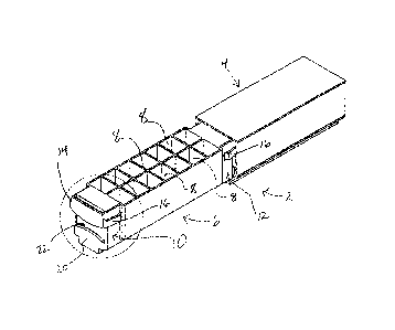
Figure 1 is a perspective view of the medication
cassette with the slidable cartridge in an extended
position;
Figure 2 is a partial perspective view showing
details of the end configuration of the cartridge;
Figure 3 is a cross-sectional view through an
intermediate portion of the extended cartridge;
Figure 4 is a sectional view through the length of
the cartridge and sleeve;
Figure 5 is a perspective view of the slidable
cartridge;
Figure 6 is an enlarged perspective view of the
end of the cartridge;
Figure 7 is a perspective view of the outer sleeve
of the cassette;
Figure 8 is a partial perspective enlargement of
the end of the sleeve of Figure 7;
Figure 9 is a perspective view of an alternate
medication cassette having a double cartridge
arrangement;
Figure 10 is a partial perspective view of one end
of one of the cartridges of Figure 9;
Figure 11 is a sectional view through the
alternate medication cassette;
Figure 12 is a longitudinal cross sectional view
through the alternate medication cassette of Figure 9;
Figure 13 is a partial perspective view showing
the alternate medication cassette with both cartridges in
a lock position;
Figure 14 is a partial perspective view of the two
ends of the cartridge of Figure 13;
Figure 15 is a sectional view through the
alternate medication cassette;
- 5 -
CA 02646029 2008-12-09
WH 13407CA
Figure 16 is a longitudinal sectional view through
the alternate medication cassette;
Figure 17 is a perspective view of the medication
cassette used in Figure 13;
Figure 18 is a partial perspective view of the end
of the medication cassette of Figure 17;
Figure 19 is an end view of the medication
cassette of Figure 17;
Figure 20 is a sectional view of the medication
cartridge of Figure 17;
Figure 21 is a perspective view of the partitioned
sleeve of the alternate medication cassette;
Figure 22 is a partial perspective view of the
outer sleeve of Figure 21;
Figure 23 is an end view of the outer sleeve of
Figure 21;
Figure 24 is a sectional view through the sleeve
of Figure 21;
Figure 25 is a side view of a medication cassette
with a label including a bar code portion; and
Figure 26 is a side view of an alternate
medication cassette with a label and bar code portion.
DETAILED DESCRIPTION OF THE PREFERRED EMBODIMENTS
The medication cassette 2 includes an outer sleeve
4 that retains the slidable cartridge 6. The slidable
cartridge includes a series of medication receiving cells
8 and each of these cells is sized to receive a single
dosage such as an individual tablet, capsule or pill.
The size of the individual cells is selected according to
the particular medications to be packaged in that some
medication capsules, for example, can be quite large. In
this case, the cartridge may only have a single row of
cells. The preferred form of the cartridge is shown in
Figures 1 through 5, where the cartridge includes a
double row of cells 8.
- 6 -
CA 02646029 2008-12-09
WH 13407CA
The cartridge 6 includes a locking arrangement 10
at one end of the cartridge and a locking arrangement 12
at the opposite end of the cartridge. Each locking
arrangement 10 and 12 includes a pair of spring arms
shown as 14 and 16 with respect to locking arrangement
10, and these spring arms are positioned to engage and
lock with the end of the sleeve. In order to allow the
cartridge to slide along the length of the sleeve, one
pair of these arms are forced inwardly against the spring
bias to allow the arms to clear the outer walls of the
sleeve and slide within the sleeve.
As shown in more detail in Figure 2, the locking
arrangement 10 is inwardly recessed and the locking arms
14 and 16 project outwardly or beyond the sides of the
cartridge. This position allows the ends of the spring
arms to engage and lock with the end of the sleeve 4.
The locking arrangement 10 is formed at an end of
the cartridge and includes an end tab 20 and an opposed
end tab 21 used during automatic loading or dispensing.
An engaging recess 23 is defined between the two tabs 20
and 21. End tab 21 includes a downwardly projecting lip
such that a bar member can be moved between the two end
tabs and end tab 21 will engage and retain the bar member
to allow the cartridge to slide within the sleeve to
expose the individual cells as the cartridge slides out
of the sleeve.
Figure 5 shows details of the slidable cartridge
6. Each end of the cartridge includes a top opening
recess 22 and a bottom opening recess 24 as shown in
Figure 4. These end portions serve to retain at least a
portion of the cartridge in the sleeve during loading or
dispensing of medication. Recesses 22 and 24 also assist
in the injection molding of the cartridge. In injection
molding, certain maximum wall thicknesses are desired to
reduce the amount of plastic material required, and to
- 7 -
CA 02646029 2008-12-09
WH 13407CA
locate the plastic to provide the desired structural
characteristics. Problems associated with cycle times
and warping during cooling can also be avoided by
eliminating areas that are difficult to cool. These
cavities provide these functions, but other cavity
arrangements can be used.
The sleeve 4, as shown in the view of Figure 3,
has a flat top portion 30, two opposed sides 32 and 34,
bottom guide sections engaging the diagonal sides of the
cartridge, and a bottom portion 37. The bottom portion
37 is U-shaped and is sized to provide a guide
arrangement with the bottom guide rails 28 and 29 of the
cartridge. The spring arms 14 and 16, shown in Figure 3
have not moved fully inwardly relative to the end
portions, and are not fully received within the sleeve 4.
As can be seen with respect to the sectional view
of Figure 4, the slidable cartridge 6 is moveable in
either direction out of the sleeve 4, but is also
moveable to a locked position with the cells 8 of the
cartridge 6 fully received and covered by the top portion
of the sleeve. In this way, the cartridge may be
progressively displaced out of the sleeve to allow access
to the individual cells 8 and allow medication in the
form of capsules, tablets, pills, etc. to be individually
loaded into one of the cells or dispensed therefrom.
Preferably, the cartridge 6 is made of a translucent
plastic to allow visual detection of any medication in
individual cells when exposed beyond the sleeve 4. The
sleeve is preferably an opaque plastic.
Details of the slidable cartridge 6 of Figure 1
are shown in Figures 5 and 6, and details of the sleeve 4
are shown in Figures 7 and 8. Figure 8 clearly shows how
the bottom surface of the sleeve 4 also includes
outwardly extending flanges 37 and 38 to define the slide
recesses 39 and 40. These slide recesses assist in
- 8 -
CA 02646029 2008-12-09
WH 13407CA
movement of the medication cassette in an automated
dispensing apparatus.
Figures 9 through 16 show details of a modified
cassette 2a having two displaceable cartridges 6a and 6b,
both received within the common sleeve 4a. The
cartridges 6a and 6b include a similar type end
configuration having a lock arrangement indicated as l0a
with spring arms 14a and 16a. These slidable cartridges
each include a series of cells 8.
The cartridges 6a and 6b are received within the
common sleeve 4a in a back to back type manner with the
open cells opening in opposite directions. Each
cartridge can only be received in the sleeve in one
orientation. The sleeve 4a also includes two recesses 7
and 9 on opposite sides of the sleeve, and these provide
the bottom guiding surfaces for each of the slidable
cartridges. The sleeve 4a also includes an interior
partition lla running the length of the sleeve. This
partition provides the slide surface for the individual
cartridges. The top and bottom surfaces 15a and 17a as
shown in Figure 15, close the open top of the cells 8
when the cartridges are received within the sleeves. The
locking arrangements of the cartridges cooperate with the
end portions of the sleeve to effect locking of the
cartridge within the sleeve in a similar manner to the
locking action described with respect to Figures 1
through S. Other locking arrangements can be used and
the locking arrangement could be reversed.
Figures 17 through 19 show further details of the
modified slide cartridge 6a.
Figures 21 through 24 show further details of the
sleeve 6a.
- 9 -
CA 02646029 2008-12-09
WH 13407CA
Figures 25 and 26 show the use of a bar code label
100 having an indicia receiving portion 102 which can
identify the particular medications that are loaded in
the cartridge, and dosage and frequency of the
medications. The barcode 104 can also provide this
information to an automated dispensing-type device or an
automatic filling-type device. The embodiment of Figure
25 shows the label 100 attached to a side of a medication
cassette having the double slidable cartridges. The
label 100a of Figure 26 includes a similar indicia
receiving portion 102a and a bar code portion 104a, and
this is attached to a medication cassette having a single
slidable cartridge.
The slidable cartridges of the medication cassette
are preferably made by injection molding and of a plastic
material. Preferably, the cartridges are of translucent
plastic that transmits a large portion of light. The
outer sleeves are preferably made of an opaque plastic
that greatly limits light transmission. The translucent
plastic of the cartridge allows visual detection signals
to confirm a medication has been received and is retained
in each individual cell. The sleeves of the medication
cassette are typically extruded plastic, cut to length to
reduce packaging costs.
The medication cassette as shown in the drawings
is preferably designed as a recyclable disposable
cassette and would be typically purchased by a user from
an authorized source such as a pharmacy. The pharmacy
would preferably have an automated machine for loading of
the medication cassette, or this loading could be done by
hand. The medication cassette can also include a tamper-
type seal that requires breaking for sliding of the
cassette.
Preferably the user would then take the medication
cassette home and load the cassette into a dispensing
- 10 -
CA 02646029 2008-12-09
WH 13407CA
device. This dispensing device preferably can read the
bar code, and based on the bar code, identify the
particular medications, the frequency at which the
medications are to be taken, and the dosage of the
individual medications loaded in the individual cells.
This automated dispensing device preferably will allow
dispensing of the medication in an appropriate manner at
different times of the day. Dispensing of the medication
includes sliding of the cartridge relative to the sleeve
to allow the contents of individual cells to be
dispensed. In the case of the double row of cells, this
dispensing device will typically cover one of the cells
to allow each cell to be dispensed individually.
Although various preferred embodiments of the
present invention have been described herein in detail,
it will be appreciated by those skilled in the art, that
variations may be made thereto without departing from the
spirit of the invention or the scope of the appended
claims.
- 11 -