Note: Descriptions are shown in the official language in which they were submitted.
CA 02646327 2008-09-17
WO 2007/109320 PCT/US2007/007019
-1-
APPLICATION OF ABNORMAL EVENT DETECTION (AED)
TECHNOLOGY TO POLYMERS PROCESS
BACKGROUND OF THE INVENTION
[0001] The present invention relates to the operation of a Polymer Process
with specific example applied to a Polypropylene Process (PP). PP in this
example comprises of nine operation areas - the catalyst preparation area (Cat
Prep), reactors (RX), recycle gas compressors, recycle gas recovery system,
the
dryers, two granule areas and two extruders system. In particular, the present
invention relates to determining when the process is deviating from normal
operation and automatic generation of notifications isolating the abnormal
portion of the process.
[0002] Polypropylene process (PP) is one of the most important and widely
used processes for polymerizing propylene to produce polypropylene.
Polypropylene is then used as intermediate materials in producing plastic
products such as milk bottles, soft drink bottles, hospital gowns, diaper
linings
etc. The PP is a very complex and tightly integrated system comprising of the
catalyst preparation unit, reactors, recycle gas compressors, recycle gas
recovery
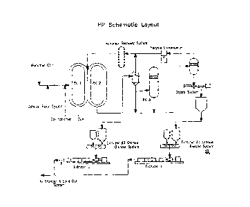
system, the dryer, granule systems and two extruders. Figure 23 shows a
typical
PP layout. The PP process employs catalysts in the form of very fine particles
mixed with cold oil and grease to form a very thick and paste - like mixture.
The thick and paste-like property of the catalyst mixture makes it difficult
to
pump catalysts into the reactors, thus makes the catalyst system prone to
plugging problems. The catalyst mixture and the fresh monomer feed
(Propylene or C3=) along with the co-monomer (Ethylene) are fed into two large
reactors (RX I & RX 2) in series. In the reactors, when the monomers are in
contact with the catalysts, a very exothermic reaction occurs and polymer
granules are formed in the reactor slurry. To remove the heat generated by the
reaction, cooling water is continuously pumped around the reactor jackets to
CA 02646327 2008-09-17
WO 2007/109320 PCT/US2007/007019
-2-
maintain the reactor temperature at a desired target. In each of the first two
reactors, there is a big pump continuously 'circulating the polymer slurry to
prevent the formation of chunks. Depending on the product grades, the PP has
two distinct reactor configuration modes - One configuration mode utilizes two
reactors (RX 1& 2) in series, while the other mode requires a third reactor
(RX
3) in series with the first two reactors. The polymer slurry exiting the
reactors is
pumped into the separators where un-reacted monomers are removed and sent to
the monomer recovery system before recycling back to the reactors. The
polymer granules are fed into the dryer system where any last trace of
monomers
is removed, any trace of catalyst residues is steam stripped and the granules
are
dried off. The dry polymer granules are sent to the granule system where they
are blended with additives and sent to the two extruders for pelletization.
The
polymer pellets are then sent the storage system or to the load out system.
[00031 Due to the complicated dynamic nature of the PP, abnormal process
operations can easily result from various root causes that can escalate to
serious
problems and even cause plant shutdowns. These operations can have significant
safety and economic implications ranging from lost production, equipment
damage, environmental emissions, injuries and death. A primary job of the
operator is to identify the cause of the abnormal situation and execute
compensatory or corrective actions in a timely and efficient manner.
[0004] The current commercial practice is to use advanced process control
applications to automatically adjust the process in response to minor process
disturbances, to rely on human process intervention for moderate to severe
abnormal operations, and to use automatic emergency process shutdown systems
for very severe abnormal operations. The normal practice to notify the console
operator of the start of an abnormal process operation is through process
alarms.
These alarms are triggered when key process measurements (temperatures,
pressures, flows, levels and compositions) violate predefined static set of
CA 02646327 2008-09-17
WO 2007/109320 PCT/US2007/007019
-3-
operating ranges. This notification technology is difficult to provide timely
alarms while keeping low false positive rate when the key measurements are
correlated for complicated processes such as PP.
[0005) There are more than'450 key process measurements, which cover the
operation of a typical PP. Under the conventional Distributed Control System
(DCS) system, the operator must survey this list of sensors and its trends,
compare them with a mental knowledge of normal PP operation, and use his/her
skills to discover the potential problems. Due to the very large number of
sensors
in an operating PP, abnormalities can be and are easily missed. With the
current
DCS based monitoring technology, the only automated detection assistance an
operator has is the DCS alarm system which is based on the alarming of each
sensor when it violates predetermined limits. In any large-scale complex
process
such as the PP, this type of notification is clearly a limitation as it often
comes in
too late for the operator to act on and mitigate the problem. The present
invention provides a more effective notification to the operator of the PP.
SUMMARY OF THE INVENTION
[0006) The present invention is a method and system for detecting an
abnormal event for the polymer process unit. In a preferred embodiment, the
polymer process is a polyolefin process. In another preferred embodiment, the
polyolefin process is a polyethylene or polypropylene process or a combination
thereof. It utilizes the existing Abnormal Event Detection (AED) technology
but
with modifications to handle the complicated dynamic nature of the PP due to
the frequent changes in operating conditions due to grade switches, and
sometimes changes in the reactor configuration to produce different product
grades. The modifications include the development of models for different
product grades, the mechanism to detect the onset of product grade switching
state, the notification suppression during the grade transitional duration,
and the
automatic switching of models presented to the operator based on changes in
the
CA 02646327 2008-09-17
WO 2007/109320 PCT/US2007/007019
-4-
operating modes, and reactor configurations. The automatic switching of the
models is in-apparent to the operators as they still utilize the same operator
interfaces. The PP AED application includes a number of highly integrated
dynamic process units. The method compares the current operation to various
models of normal operation for the covered units. If the difference between
the
operation of the unit and the normal operation indicates an abnormal condition
in
a process unit, then the cause of the abnormal condition is determined and
relevant information is presented efficiently to the operator to take
corrective
actions.
BRIEF DESCRIPTION OF THE DRAWINGS
[0007] Figure 1 shows how the information in the online system flows
through the various transformations, model calculations, fuzzy Petri nets and
consolidation to arrive at a summary trend which indicates the normality/
abnormality of the process areas.
[0008] Figure 2 shows a valve flow plot to the operator as a simple x-y plot.
[0009] Figure 3 shows three-dimensional redundancy expressed as a PCA
model.
[0010] Figure 4 shows a schematic diagram of a fuzzy network setup.
[0011] Figure 5 shows a schematic diagram of the overall process for
developing an abnormal event application.
[0012] Figure 6 shows a schematic diagram of the anatomy of a process
control cascade.
[0013] Figure 7 shows a schematic diagram of the anatomy of a
multivariable constraint controller, MVCC.
[0014] Figure 8 shows a schematic diagram of the on-line inferential
estimate of current quality.
CA 02646327 2008-09-17
WO 2007/109320 PCT/US2007/007019
-5-
[0015] Figure 9 shows the KPI analysis of historical data.
[0016] Figure 10 shows a diagram of signal to noise ratio.
[0017] Figure 11 shows how the process dynamics can disrupt the
correlation between the current values of two measurements.
[0018] Figure 12 shows the probability distribution of process data.
[0019] Figure 13 shows illustration of the press statistic.
[0020] Figure 14 shows the two-dimensional energy balance model.
[0021] Figure 15 shows a typical stretch of Flow, Valve Position, and Delta
Pressure data with the long period of constant operation.
[0022] Figure 16 shows a type 4 fuzzy discriminator.
[0023] Figure 17 shows a flow versus valve paraeto chart.
[0024] Figure 18 shows a schematic diagram of operator suppression logic.
[0025) Figure 19 shows a schematic diagram of event suppression logic.
[0026] Figure 20 shows the setting of the duration of event suppression.
[0027] Figure 21 shows the event suppression and the operator suppression
disabling predefmed sets of inputs in the PCA model.
[0028) Figure 22 shows how design objectives are expressed in the primary
interfaces used by the operator
[0029] Figure 23 shows the simplified schematic layout of a PP
[0030] Figure 24 shows the operator display of all the problem monitors for
the PP operation.
[0031] Figure 25 shows the fuzzy-logic based continuous abnormality
indicator for the Catalyst Plugging problem in the Poly8 Operation Area.
CA 02646327 2008-09-17
WO 2007/109320 PCT/US2007/007019
-6-
100321 Figure 26 shows AED alerts of the Catalyst Plugging Problem in
both the Poly 8 Operation, and the Poly8 Cat Area abnormality monitors.
[0033] Figure 27 shows that complete drill down for the Catalyst Plugging
problem in the Poly8 Operation Area along with the supporting evidences.
[0034] Figure 28 shows the drill down for the Catalyst Plugging problem in
the PolyB Cat Area with location of problem area.
[0035] Figure 29 shows the fuzzy logic network for detection of the
Catalyst Plugging problem in the Poly8 Cat Area.
[0036] Figure 30 shows Fuzzy Logic Network couple with rules developed
for automatic switching of PCA models underlying Poly 8 Operation
[0037] Figure 31 shows the Fuzzy Logic Network developed for automatic
detection of grade switches and for setting process transitional duration
[0038] Figure 32 shows A Pareto Chart displaying the residuals of the
deviating sensors corresponding to the Catalyst Plugging Problem highlighted
in
Figure 27.
[0039] Figure 33 shows the multi-trends for the tags in Figure 32. It shows
the tag values and also the model predictions.
[0040] Figure 34 shows the pareto chart ranking the deviating valve flow
models
[0041] Figure 35 shows the X-Y plot for a valve flow model - valve
opening versus the flow.
[0042] Figure 36 shows the drill down for the controller monitors and
Sensor validation checks.
[0043] Figure 37 shows the fuzzy logic network for the controller monitors
and Sensor validation checks.
CA 02646327 2008-09-17
WO 2007/109320 PCT/US2007/007019
-7-
[00441 Figure 3 8 shows the drill down for the heuristic models.
[0045] Figure 39 shows the fuzzy logic for the heuristic models
[0046] Figure 40 shows a Valve Flow Monitor Fuzzy Net.
[0047] Figure 41 shows an example of valve out of controllable range.
[0048] Figure 42 shows a standard statistical program, which plots the
amount of variation modeled by each successive PC.
[0049] Figure 43 shows the Event Suppression display.
[0050] Figure 44 shows the AED Event Feedback Form.
DETAILED DESCRIPTION OF THE PREFERRED EMBODIMENTS
[0051] The present invention is a method to provide early notification of
abnormal conditions in sections of the PP to the operator using a modified
Abnormal Event Detection (AED) technology. The modifications include the
development of different models for different product grades, and the
automatic
switching of models presented to the operator based on changes in the
operating
modes, and reactor configurations. The switching of the models is in-apparent
to
the operators as they still utilize the same operator interfaces. The PP AED
application includes a number of highly integrated dynamic process units. The
method compares the current operation to various models of normal operation
,
for the covered units. If the difference between the operation of the unit and
the
normal operation indicates an abnormal condition in a process unit, then the
cause of the abnormal condition is determined and relevant information is
presented efficiently to the operator to take corrective actions.
[0052] In contrast to alarming techniques that are snapshot based and
provide only an on/off indication, this method uses fuzzy logic to combine
multiple supportive evidences of abnormalities that contribute to an
operational
problem and estimates its probability in real-time. This probability is
presented
CA 02646327 2008-09-17
WO 2007/109320 PCT/US2007/007019
-8-
as a continuous signal to the operator thus removing any chattering associated
with the current single sensor alarming-based on/off methods. The operator is
provided with a set of tools that allow complete investigation and drill down
to
the root cause of a problem for focused action. This approach has been
demonstrated to furnish the operator with advanced warning of the abnormal
operation that can be minutes to hours earlier than the conventional alarm
system. This early notification lets the operator make informed decision and
take
corrective action to avert any escalation or mishaps. This method has been -
successfully applied to the PP. As an example, Figure 27 shows the complete
drill down for the Catalyst Plugging problem in the Poly8 Operation area (the
details of the subproblems are described later).
(0053] The PP AED application uses diverse sources of specific operational
knowledge to combine indications from Principal Component Analysis (PCA),
correlation-based engineering models such as Valve Flow models (VFM),
heuristic models (H1VI) or specific "operating rules-of-thumb" collected from
experienced operators that are constructed in the fuzzy logic network,
Controller
Monitoring and Sensor Consistency Check (CM) to monitor relevant sensors
through the use of fuzzy logic networks. This fuzzy logic network aggregates
the evidence and indicates the combined confidence level of a potential
problem.
Therefore, the network can detect a problem with higher confidence at its
initial
developing stages and provide crucial lead-time for the operator to take
compensatory or corrective actions to avoid serious incidents. This is a key
advantage over the present commercial practice of monitoring PP based on
single sensor alarming from a DCS system. Very often the alarm comes in too
late for the operator to mitigate an operational problem due to the
complicated,
fast dynamic nature of PP or multiple alarms could flood the operator,
confusing
him/her and thus hindering rather than aiding in response.
CA 02646327 2008-09-17
WO 2007/109320 PCT/US2007/007019
-9-
[0054] The PP unit is divided into equipment groups (referred to as key
functional sections or operational sections). These equipment groups may be
different for different PP units depending on its design. The procedure for
choosing equipment groups which include specific process units of the PP unit
is
described in Appendix 1.
[0055] In the preferred embodiment, the present invention divides the
Polypropylene Unit (PP) operation into the following overall monitors
1. Overall Polymerization Operation (Poly8 Operation)
2. Overall Dryers Operation (Dryer8 Operation)
3. Overall Extruderl Operation (EX801 Operation)
4. Overall Extruderl Operation (EX831 Operation)
and these special concern monitors
1. Flow Control Valve Monitoring (Poly8 Control Valves)
2. Catalyst Area Alerts (Poly8 Cat Area Alerts)
3. Sensor Checks (Poly8 Sensors)
4. Sensor Checks (Poly4 Sensors)
5. 831 Granules Area Alerts
6. 801 Granules Area Alerts
7. Finishing 4 Area Alerts
[0056] The overall monitors carry out "gross model checking" to detect any
deviation in the overall operation and cover a large number of sensors. The
special concern monitors cover areas with potentially serious concerns and
consist of focused models for early detection. In addition to all these
monitors
the application provides for several practical tools such as those dealing
with
CA 02646327 2008-09-17
WO 2007/109320 PCT/US2007/007019
-10-
suppression of notifications generated from normal/routine operational events
and elimination of false positives due to special cause operations.
A. Operator Interface
[0057] The operator user interface is a critical component of the system as it
provides the operator with a bird's eye view of the process. The display is
intended to give the operator a quick overview of PP operations and indicate
the
probability of any developing abnormalities.
[0058] Figure 24 shows the operator interface for the system. A detailed
description on operator interface design considerations is provided in
subsection
IV "Operator Interaction & Interface Design" under section "Deploying PCA
models and Simple Engineering Models for AEDD" in Appendix 1 section IV,
under The interface consists of the abnormality monitors mentioned above. This
was developed to represent the list of important abnormal indications in each
operation area. Comparing model results with the state of key sensors
generates
abnormal indications. Fuzzy logic is used to aggregate abnormal indications to
evaluate a single probability of a problem. Based on specific knowledge about
the normal operation of each section, we developed a fuzzy logic network to
take
the input from sensors and model residuals to evaluate the probability of a
problem. Figure 25 shows the probability for the Catalyst Plugging problem in
the Poly8 Cat area using the corresponding fuzzy logic network shown in Figure
29. Figure 26 shows that the Catalyst Plugging Problem is seen in both the
Poly
8 Operation and PolyB Cat Area abnormality monitors. Figure 27 shows the
complete drill down of the catalyst plugging problem in the Poly8 Operation
Area. Figure 28 shows the complete drill down of the catalyst plugging problem
in the Poly8 Cat Area identifying the location of the plug. Figure 29 shows
the
fuzzy logic network with the green nodes indicating the subproblems that
combine together to determine the final certainty of the Catalyst Plugging
Problem in the Poly8 Cat Area. The estimated probability of an abnormal
CA 02646327 2008-09-17
WO 2007/109320 PCT/US2007/007019
-11-
condition is shown to the operating team in a continuous trend to indicate the
condition's progression as shown in Figure 26. This gives the operator a
significant advantage to get an overview of the health of the process than
having
to check the status of each sensor individually. More importantly, it gives
the
operator 'peace-of-mind' - due to its extensive coverage, chances of missing
any
event are remote. So, it is can also be used as a normality-indicator. When
the
probability reaches 0.6, the problem indicator turns yellow (warning) and the
indicator turns red (alert) when the probability reaches 0.9.
[0059] This invention comprises five Principle Component Analysis (PCA)
models to cover the areas of Cat. Prep., the Reactors including two Loop
Reactors (RX 1& 2) and a Gas Phase Reactor (RX 3), the Monomer Gas
Recycle System, Recycle Gas Compressor, the dryers, the granule areas and two
extruders system including Extruders 801 area, and Extrusion EX831 area. The
coverage of the PCA models was determined based on the interactions of the
different processing units and the models have overlapping sensors to take
this
into account. Since there is significant interaction in the Cat. Prep, the
Reactors,
and Monomer Gas Recycle system and the Recycle Gas Compressor, these areas
are combined to represent the "Poly8 Operation". Since PP has two distinct
operating conditions using two reactor configuration modes to produce
different
product grades - one mode using two reactors in series, and the other mode
using three reactors in series, it is necessary to have two PCA models to
handle
those two modes. However, only one PCA model is on-line at a time to underlie
Poly8 Operation". In this case, fuzzy logic network is used to automatically
switch the online PCA model to the appropriate model. Figure 30 shows the
fuzzy logic network designed to automatically detect the onset of the switch
and
switch the online PCA model underling Poly8 Operation. The third PCA model
combines the dryers, and the granule areas to represent the "Dryers8
Operation".
The fourth and fifth PCA models represent the two extrusion areas labeled as
"EX801 Operation", and "EX831 Operation". In addition, there are a number
CA 02646327 2008-09-17
WO 2007/109320 PCT/US2007/007019
-I2-
of special concern monitors intended to watch conditions that could escalate
into
serious events. The objective is to detect the problems early on so that the
operator has sufficient lead time to act.
[00601 Under normal operations, the operator executes several routine
actions such as feed rate changes, setpoint moves that could produce short-
lived
high residuals in some sensors in the PCA models. Since such notifications are
redundant and do not give new information, this invention has mechanism built-
in to detect their onset and suppress the notifications. As part of PP routine
operations, product grade switches are done very frequently, which make PP a
very fast dynamic process. There are grade switches within a product grade
family (called flying grade-switch) that do not require changes in reactor
configuration). In this case, operators can make large setpoint changes to
some
key product-quality controllers to steer the PP to a new operation state.
During
the transitional state, some sensors will experience high residuals and
therefore
depict abnormal conditions. The existing AED notification - suppression
mechanism could not handle the grade switches, and therefore modifications
were made. The modifications include mechanism to detect the onset of a grade
switch and set a grade -switch state. The grade switch state is then latched
on
for a certain period of time to depict a process transitional duration. During
the
transitional duration, the notifications are suppressed using the existing
mechanism to avoid flooding operators with nuisance alerts, as they are
already
aware of the condition changes, and are already keeping a close watch of the
PP.
However, during the transitional duration, AED continues to update PCA model
parameters, and once the PP reaches its new steady state, AED resumes its
notification. Figure 31 shows the added fuzzy network logics for automatic
detection of grade switches and for setting the transitional duration. There
are
also product grade switches requiring changes in reactor configuration (from
two
reactor mode to three reactor mode and vice versa). This modification of the
AED notification suppression also handles the suppression for this case.
CA 02646327 2008-09-17
WO 2007/109320 PCT/US2007/007019
-13-
[0061] The operator is informed of an impending problem through the
warning triangles that change color from green to yellow and then red. The
application provides the operator with drill down capability to further
investigate
the problem by viewing a list of prioritized subproblems. This novel method
provides the operator with drill down capabilities to the subproblems. This
enables operators to narrow down the search for the root cause, and assists
them
in isolating and diagnosing the root cause of the condition so that
compensatory
or corrective actions can be taken sooner than later. As previously shown in
Figure 27, a pareto chart indicating the residuals of the deviating sensors
sorted
by their deviations is displayed when operators click on the red triangles to
drill
down to the subproblems.
[0062] The application uses the pareto-chart approach quite extensively to
present information to the operator. The sequence of presentation is in
decreasing
order of individual deviation from normal operation. This allows a succinct
and
concise view of the process narrowed down to the few critical bad actors so
the
console operator can make informed decisions about course of action. Figure 32
demonstrates this functionality through a list of sensors organized in a
pareto-
chart. Upon clicking on an individual bar, a custom plot showing the tag trend
versus model prediction for the sensor is created. The operator can also look
at
trends of problem sensors together using the "multi-trend view". For instance,
Figure 33 shows the trends of the value and model predictions of the sensors
in
the Pareto chart of Figure 32. Figure 34 shows the same concept, this time
applied to the ranking of valve-flow models (VFM) based on the normalized-
projection-deviation error. Clicking on the bar in this case, generates an X-Y
scatter plot that shows the current operation point in the context of the
bounds of
normal operation (Figure 35).
[0063] In addition to the PCA models, there are a number of special
concern monitors built using engineering relationships such as the VFM, the
CA 02646327 2008-09-17
WO 2007/109320 PCT/US2007/007019
-14.-
controller monitorings (CM), the sensor checks (SC), and the heuristic models
(FM). The VFMs cover critical equipment in the Poly8 Control Valves. The
HMs cover the critical equipment plugging problems in the PolyB Cat, the 801
Granule, the 831 Granule, and the Finsihing4 Areas. The CM and SC covers
the critical controllers and sensors in the PolyB Sensor Check, and Poly4
Sensor
Check Areas. Underlying these monitors are fuzzy-logic networks that generate
a single abnormality signal in each area. Figure 36 shows the drill down for
the
controller monitors and Sensor checks. Figure 37 shows the fuzzy logic network
for the controller monitors and Sensor checks. Figure 38 shows the drill down
for the heuristic models. Figure 39 shows the fuzzy logic for the heuristic
models
[00641 In summary, the advantages of this invention include:
1. The modification of existing Abnormal Event Detection (AED)
technology to successfully handle the frequent changes in
operating conditions due to grade switches, and sometimes
changes in the reactor configuration to produce different product
grades.
2. The decomposition of the entire PP operation into 11
operational areas - the Polymerization Reactors, the Dryers, the
Extrusion EX83 1, the Extrusion EX801, the Poly8 Flow Control
Valves, the Poly8 Catalyst Preparation, Poly8 Sensors, 831
Granules, 801 Granules, and Finishing 4 for supervision.
3. The operational condition of the entire PP is summarized into 11
single alerts
4. The PCA models provide model predictions of the 450+ sensors
covered in the models.
CA 02646327 2008-09-17
WO 2007/109320 PCT/US2007/007019
-15-
5. The abnormal deviations of these sensors are summarized by the
alerts based on the Sum of Square Error of the 5 PCA models
6. The valve-flow models provide a powerful way to monitor
control loops, which effect control actions and thus can be the
source or by affected by upsets.
7. The heuristic models covering the critical equipment plugging
problems in the PolyB Cat, the 801 Granule, the 831 Granule,
and the Finsihing4 Areas add enhanced focused and early
detection capability.
8. The controller monitors and the sensor checks add enhanced
focused and early detection capability for key process variables.
9. Events resulting from special cause/routine operations are
suppressed to eliminate the false positives. The enormous
dimensionality reduction from 450+ individual tags to just 12
signals significantly cuts down on the false positive rate. The
PCA modeling approach inherently resolves the single sensor
alarming issue in an elegant manner.
B. Development and Deployment of AED Models for PP
[0065] The application has PCA models, engineering models and heuristics
to detect abnormal operation in a PP. The first steps involve analyzing the
concerned unit for historical operational problems. This problem
identification
step is important to define the scope of the application.
[0066] The development of these models is described in general in
Appendix 1. Some of the specific concerns around building these models for the
PP unit are described below.
CA 02646327 2008-09-17
WO 2007/109320 PCT/US2007/007019
-16-
Problem Identification
[0067] The first step in the application development is to identify a
significant problem, which will benefit.process operations. The abnormal event
detection application in general can be applied to two different classes of
problem. The first is a generic abnormal event application that monitors an
entire
process area looking for any abnormal event. This type will use several
hundred
measurements, but does not require a historical record of any specific
abnormal
operations. The application will only detect and link an abnormal event to a
portion (tags) of the process. Diagnosis of the problem requires the skill of
the
operator or engineer.
[0068] The second type is focused on a specific abnormal operation. This
type will provide a specific diagnosis once the abnormality is detected. It
typically involves only a small number of measurements (5 -20), but requires a
historical data record of the event. These models can be PCA based or simple
engineering correlation such as the Valve Flow (VF) models monitoring the
main process flow valves for broken correlation or out-of-range operation that
are constructed based on historical data of sensors around the flow control
valve
such as upstream/downstream pressure, flow measurement and valve output; the
Heuristic Models (HM) are specific "operating rules-of-thumb" collected from
experienced operators and are constructed in the fuzzy logic network to
identify
those circumstances that violate these rules-of-thumb; the Controller
Monitoring
(CM) and Sensor Check (SC) monitor the performance of the controller or
sensor to detect a frozen instrument, a controller malfunction, or an
instrument
that has a highly variant reading. This invention uses the above models in
order
to provide extensive coverage. The operator or the engineer would then rely on
their process knowledge / expertise to accurately diagnose the cause.
Typically
most of the events seem to be primarily the result ofproblems with the
instruments and valves.
CA 02646327 2008-09-17
WO 2007/109320 PCT/US2007/007019
- i7-
[0069] The following problem characteristics should be considered when
selecting an abnormal event detection problem: Infrequent abnormalities (every
3 - 4 months) may not justify the effort to create an abnormal event detector.
Also, when a particular abnormality occurs only every 3 or 4 months, an
individual operator may go for years without seeing the event. As a
consequence, he would not know what to do once the event finally occurs.
Therefore the problem identification should be broad enough that the operator
would be regularly interacting with the application.
[0070] When scoping the problem, it is common to get the wrong
impression from site personnel that there would not be a sufficient number of
abnormal events to justify an abnormal event detection application. In
general,
an overly low estimate of how frequently abnormal events affect the process
occurs because:
= Abnormal events are often not recorded and analyzed. Only those
that cause significant losses are tracked and analyzed.
= Abnormal events are often viewed as part of normal operations
since operators deal with them daily.
Unless there is a regularly repeating abnormal event, the application should
cover a large enough portion of the process to "see" abnormal events on a
regular basis (e.g. more than 5 times each week).
1. PCA Models
[0071] The PCA models are the heart of the PP AED. PCA transforms the
actual process variables into a set of 'orthogonal' or independent variables
called
Principal Components (PC) which are linear combinations of the original
variables. It has been observed that the underlying process has a number of
degrees of freedom which represent the specific independent effects that
CA 02646327 2008-09-17
WO 2007/109320 PCT/US2007/007019
-18-
influence the process. These different independent effects show up in the
process
data as process variation. Process variation can be due to intentional
changes,
such as feed rate changes, or unintentional disturbances, such as ambient
temperature variation.
[0072] Each principal component captures a unique portion of the process
variability caused by these different independent influences on the process.
The
principal components are extracted in the order of decreasing process
variation.
Each subsequent principal component captures a smaller portion of the total
process variability. The major principal components should represent
significant underlying sources of process variation. As an example, the first
principal component often represents the effect of feed rate changes since
this is
usually the largest single source of process changes.
[0073] The application is based on a Principal Component Analysis, PCA,
of the process, which creates an empirical model of "normal operations". The
process of building PCA models is described in detail in the section
"Developing
PCA Models for AED" in Appendix 1. The following will discuss the special
considerations that are necessary to apply PCA toward creating an abnormal
event detection application for Polymers Process.
PP PCA Model Development
[0074] There are five PCA models developed for PP. The two PCA models
underlying the PoIy8 Operation to cover the two reactor configuration modes
are
PolyB TCR and Poly8_ICP. These two PCA models include sensors in the
Catalyst Preparation, the Reactors, the Monomer Gas Recycle system and the
Recycle Gas Compressor because there is significant interaction between these
systems. The Poly8_TCR PCA model started with an initial set of 321 tags,
which was then refined to 155 tags. The PolyB_ICP PCA model started with an
initial set of 414 tags, which was then refined to 200 tags. The Dryer8 model
started with an initial set of 76 tags in the dryers, and the granule areas,
which
CA 02646327 2008-09-17
WO 2007/109320 PCT/US2007/007019
-19-
was then refined to 37 tags. The EX801 model narrowed down from 43 to 25
tags to cover the extrusion 1 area. The EX831 model narrowed down from 43 to
25 tags to cover the extrusion 2 area. The details of the PolyB TCR PCA model
is shown in Appendix 2A, the Poly8_ICP PCA model in Appendix 2B, the
Dryer8 PCA model in Appendix 2C, the EX801 PCA model in Appendix 2D,
the EX83 1PCA model in Appendix 2E. This allows extensive coverage of the
overall PP operation and early alerts.
[00751 The PCA model development comprises of the following steps:
1) Input Data and Operating Range Selection
2) Historical data collection and pre-processing
3) Data and Process Analysis
4) Initial model creation
5) Model Testing and Tuning
6) Model Deployment
[0076] The general principles involved in building PCA models are
described in the subsection I "Conceptual PCA Model Design" under section
"Developing PCA Models for AED" in Appendix 1 These steps constitute the
primary effort in model development. Since PCA models are data-driven, good
quality and quantity of training data representing normal operations is very
crucial. The basic development strategy is to start with a very rough model,
then
to successively improve that model's fidelity. This requires observing how the
model compares to the actual process operations and re-training the model
based
on these observations. The steps are briefly described next.
Input Data and Operating Range Selection
[0077] As the list of tags in the PCA model dictates coverage, we start with
a comprehensive list of all the tags in the concerned areas. The process of
CA 02646327 2008-09-17
WO 2007/109320 PCT/US2007/007019
-2Q-
selecting measurements and variables is outlined in subsection II "Input Data
and Operating Range Selection" under the section "Developing PCA Models for
AED" in Appendix 1. Any measurements that were known to be unreliable or
exhibit erratic behavior should be removed from.the list. Additional
measurement reduction is performed using an iterative procedure once the
initial
PCA model is obtained. The specific concern around input data selection for
PP is the development of tag list to handle the two reactor configuration
modes.
The tag list for the three - reactor mode includes tags to cover the operation
of all
three reactors, while the tag list for the two - reactor mode contains tags
for two
reactors. The specific concern around operating range selection for PP is to
make sure the range covers the process operating conditions of all product
grades.
Historical Data collection and Pre-Processing
[0078] Developing a good model of normal operations requires a training
data set of normal operations. This data set should:
= Span the normal operating range
= Only include normal operating data
[0079] Because it is very rare to have a complete record of the abnormal
event history at a site, historical data can only be used as a starting point
for
creating the training data set. Operating records such as Operator logs,
Operator
Change Journals, Alarm Journals, Instrument Maintenance records provide a
partial record of the abnormal process history. The process of data collection
is
elaborated upon in subsection III "Historical Data collection" under the
section
"Developing PCA Models for AED" in Appendix I.
[0080] In the PP case, the historical data spanned 1.5 years of operation to
cover the production of all product grades as well as both summer and winter
seasons. With one-minute averaged data the number of time points turn out to
be
CA 02646327 2008-09-17
WO 2007/109320 PCT/US2007/007019
-21-
around 700,000+ for each tag. In order to make the data-set more manageable
while still retaining underlying information, the tag list was divided up into
two
sub-sets of tags for data collection and analysis.
[0081] Basic statistics such as average, min/max and standard deviation are
calculated for all the tags to determine the extent of variation/information
contained within. Also, operating logs were examined to remove data contained
within windows with known unit shutdowns or abnormal operations. Each
candidate measurement was scrutinized to determine appropriateness for '
inclusion in the training data set.
Creating Balanced Training Data Set
100821 Using the operating logs, the historical data is divided into periods
with known abnormal operations and periods with no identified abnormal
operations. The data with no identified abnormal operations will be the
preliminary training data set. For PP, operating logs were studied to
determine
the time periods when each product grade is produced. The historical data set
is
then divided up and saved by the grade families. Each grade family data set is
then analyzed for exclusion of periods with known abnormal operations and
periods with no identified abnormal operations.
[0083] Once these exclusions have been made the first rough PCA model is
built for each grade family. Since this is going to be a very rough model the
exact number of principal components to be retained is not important. This
should be no more than 5% of the number measurements included in the model.
The number of PCs should ultimately match the number of degrees of freedom
in the process, however this is not usually known since this includes all the
different sources of process disturbances. There are several standard methods
for determining how many principal components to include. Also at this stage
the statistical approach to variable scaling should be used: scale all
variables to
unit variance.
CA 02646327 2008-09-17
WO 2007/109320 PCT/US2007/007019
_22_
[0084] The training data set should now be run through this preliminary
model to identify time periods where the data does not match the model. These
time periods should be examined to see whether an abnormal event was
occurring at the time. If this is judged to be the case, then these time
periods
should also be flagged as times with known abnormal events occurring. These
time periods should be excluded from the training data set and the model
rebuilt
with the modified data. The process of creating balanced training data sets
using
data and process analysis is outlined in Section IV "Data & Process Analysis"
under the section "Developing PCA Models for AED" in Appendix 1.
Initial Model Creation
[0085] The model development strategy is to start with a very rough model
(the consequence of a questionable training data set) then use the model to
gather a high quality training data set. This data is then used to improve the
model, which is then used to continue to gather better quality training data.
This
process is repeated until the model is satisfactory.
[0086] Once the specific measurements have been selected and the training
data set has been built, the model can be built quickly using standard
statistical
tools. An, example of such a program showing the percent variance captured by
each principle component is shown in Figure 42.
The model building process is described in Section V "Model Creation" under
the section "Developing PCA Models for AED" in Appendix 1.
Model Testing and Tuning
[0087] Once the initial model has been created, it needs to be enhanced by
creating a new training data set. This is done by using the model to monitor
the
process. Once the model indicates a potential abnormal situation, the engineer
should investigate and classify the process situation. The engineer will find
three different situation, either some special process operation is occurring,
an
CA 02646327 2008-09-17
WO 2007/109320 PCT/US2007/007019
- 23 -
actual abnormal situation is occurring, or the process is normal and it is a
false
indication.
[00881 The process data will not have a gaussian or norma] distribution.
Consequently, the standard statistical method of setting the trigger for
detecting
an abnormal event from the variability of the residual error should not be
used.
Instead the trigger point needs to be set empirically based on experience with
using the model. Section VI "Model Testing & Tuning" under the section
"Developing PCA Models for AED" in Appendix 1 describes the Model testing
and enhancement procedure.
PCA Model Deployment
[0089] Successful deployment of AED on a process unit requires a
combination of accurate models, a well designed user interface and proper
trigger points. The detailed procedure of deploying PCA model is described
under "Deploying PCA Models and Simple Engineering Models for AED" in
Appendix 1.
[0090] Over time, the developer or site engineer may determine that it is
necessary to improve one of the models. Either the process conditions have
changed or the model is providing a false indication. In this event, the
training
data set could be augmented with additional process data and improved model
coefficients could be obtained. The trigger points can be recalculated using
the
same rules of thumb mentioned previously.
[0091] Old data that no longer adequately represents process operations
should be removed from the training data set. If a particular type of
operation is
no longer being done, all data from that operation should be removed. After a
major process modification, the training data and AED model= may need to be
rebuilt from scratch.
CA 02646327 2008-09-17
WO 2007/109320 PCT/US2007/007019
-24-
[0092] In addition to the PCA models, there are a number of special
concern monitors intended to watch conditions that could escalate into serious
events. These monitors were developed based on simple engineering correlation
such as the Valve Flow models (VFM), the Controller Monitoring (CM) and
Sensor Check (SC), or the specific "operating rules-of-thumb" collected from
experienced operators (heuristic models - HM).
II. Other PP AED Models
Engineering Models Development
[0093] The engineering models comprise of correlation-based models
focused on specific detection of abnormal conditions. The detailed description
of
building engineering models can be found under "Simple Engineering Models
for AED" section in Appendix 1.
[0094] The engineering model requirements for the PP application were
determined by performing an engineering evaluation of historical process data
and interviews with console operators and equipment specialists. The
engineering evaluation included areas of critical concern and worst case
scenarios for PP operation. To address the conclusions from the engineering
assessment, the following engineering models were developed for the PP AED
application:
= Valve-Flow Models (VFM)
= Controller monitors (CM)
= Sensor Checks (SC)
[0095] The Flow-Valve position consistency monitor was derived from a
comparison of the measured flow (compensated for the pressure drop across the
valve) with a model estimate of the flow. These are powerful checks as the
condition of the control loops are being directly monitored in the process.
The
model estimate of the flow is obtained from historical data by fitting
coefficients
CA 02646327 2008-09-17
WO 2007/109320 PCT/US2007/007019
-25-
to the valve curve equation (assumed to be either linear or parabolic). In the
PP
AED application, 20 flow/valve position consistency models were developed.
An example is shown in Figure 35 for the Monomer Flow Valve. Several
models were also developed for the flow control loops which historically
exhibited unreliable performance. The details of the valve flow models are
given in Appendix 3 A.
[0096] In addition to the valve-flow model mismatch, there is an additional
check to notify the operator in the event that a control valve is beyond
controllable range using value-exceedance. Figure 41 shows both the
components of the fuzzy network and an example of value-exceedance is shown
in Figure 40
[0097] A time-varying drift term was added to the model estimate to
compensate for long term sensor drift. The operator can also request a reset
of
the drift term after a sensor recalibration or when a manual bypass valve has
been changed. This modification to the flow estimator significantly improved
the
robustness for implementation within an online detection algorithm.
[00981 The controller monitors (CM) and sensor checks (SC) were derived by
analyzing the historical data and applying simple engineering calculations.
The
model for the CM was derived from calculation of the standard of deviation
(SD) to detect a frozen instrument in the case the measurement experiences
very
low SD or a highly variant instrument when the measurement experiences high
SD. Other calculations for CM include the accumulation of the length of time
during which the measurement is not meeting and not criss-crossing the
setpoint,
and also the accumulation of the deviation between the measurement and the
setpoint to detect the controller malfunction. The model for the SC was
obtained
by analyzing the historical data for the relationship between measurements.
These are powerful checks as the condition of the controllers or the sensors
are
being directly monitored and compared to the models. The details of the
CA 02646327 2008-09-17
WO 2007/109320 PCT/US2007/007019
-26-
measurement correlation are given in Appendix 3 B. The abnormal monitor
with drill down to the subproblem is shown in Figure 36. The components of the
fixzzy network are shown in Figure 37.
[0099] The heuristic models (HM) are specific "operating rules-of-thumb"
collected from experienced operators. These models identify those
circumstances that violate these rules-of-thumb. An example is the monitoring
of 801 granule area process variables to detect potential line plugging
problems
with the details given in Appendix 3 C. The abnormal monitor with drill down
to the subproblem is shown in Figure 38. The components of the fuzzy network
are shown in Figure 39.
Engineering Model & Heuristic Model Deployment
[00100] ' The procedure for implementing the engineering models within
AED is fairly straightforward. For the computational models (e.g. VFM, CM
and SC) the trigger points for notification were initially derived from the
standard deviation of the model residual. For the heuristic models which
identify
specific known types of behavior within the unit (e.g. the Poly8 Cat, 801
Granule area, 831 Granule area, and Finishing 4 area operation), the trigger
points for notification were determined from the analysis of historical data
in
combination with console operator input. For the first several months of
operation, known AED indications were reviewed with the operator to ensure
that the trigger points were appropriate and modified as necessary. Section
"Deploying PCA Models and Simple Engineering Models for AED" in
Appendix 1 describes details of engineering model deployment.
[00101] Under certain circumstances, the valve/flow diagnostics could
provide the operator with redundant notification. Model suppression was
applied to the valve / flow diagnostics to provide the operator with a single
alert
to a problem with a valve/flow pair.
CA 02646327 2008-09-17
WO 2007/109320 PCT/US2007/007019
-27-
C. AED Additional Tools
[00102] In order to facilitate smooth daily AED operation, various tools are
provided to help maintain AED models and accommodate real concerns.
Event sunpression/Taizs Disabling
[00103] Under normal operations, the operator executes several routine
actions (e.g., setpoint changes, tags under maintenance, and pump swaps).
These moves could produce short-lived high residuals in some sensors. In
practice if the AED models are not already aware of such changes, the result
can
be an abnormality signal. Since such notifications are redundant and do not
give
new information, this invention has mechanism built-in to detect their onset
and
suppress the event notifications. To temporary suppress the event
notification, a
fuzzy net uses the condition checks to suppress the specified tags. In other
situations, tags in PCA models, valve flow models and fuzzy nets can be
temporarily disabled for specified time periods. In most cases, a reactivation
time of 12 hours is used to prevent operators from forgetting to reactivate.
If a
tag has been removed from service for an extended period, it can also be
disabled. In the case of PP routine operations, product grade switches are
done
very frequently. There are grade switches within a product grade family
(called
flying grade-switch) that do not require changes in reactor configuration. In
this
case, operators can make large setpoint changes to some key product-quality
controllers to steer the PP to a new operation state. During the transitional
state,
some sensors will experience high residuals and therefore depict abnormal
conditions. Modifications were made to the existing AED notification -
suppression mechanism to handle the grade switches. The modifications
include mechanism to detect the onset of a grade switch and set a grade -
switch
state. The grade switch state is then latched on for a certain period of time
to
depict a process transitional duration. During the transitional duration, the
notifications are suppressed using the existing mechanism to avoid flooding
CA 02646327 2008-09-17
WO 2007/109320 PCT/US2007/007019
-28-
operators with nuisance alerts. However, during the transitional duration, AED
continues to update PCA model parameters, and once the PP reaches its new
steady state, AED resumes its notification. Figure 31 shows the fuzzy logic
network for automatic detection of grade switches and for setting the
transitional
duration. There are also product grade switches requiring changes in reactor
configuration (from two reactor mode to three reactor mode and vice versa).
This modification of the AED notification suppression also handles the
suppression for this case. The list of events currently suppressed is shown in
Figure 43.
Logging Event Details
[00104] To derive the greatest benefits from such a system, it is necessary
to train the operators and incorporate the AED system into the daily 'work
process. Since the final authority still rests with the operator to take
corrective
actions, it is important to get their input on AED performance and
enhancements. In order to capture AED event details in a systematic manner to
review and provide feedback, the operators were provided with AED Event
Forms. These helped maintain a record of events and help evaluate AED
benefits. Since the time AED was commissioned, several critical events have
been captured and documented for operations personnel. A sample form is
shown in Figure 44.
Alternative Solutions May Be Better -Corrective actions for repeated events
[00105] If a particular repeating problem has been identified, the developer
should confirm that there is not a better way to solve the problem. In
particular
the developer should make the following checks before trying to build an
abnormal event detection application.
= Can the problem be permanently fixed? Often a problem exists
because site personnel have not had sufficient time to
investigate and permanently solve the problem. Once the
CA 02646327 2008-09-17
WO 2007/109320 PCT/US2007/007019
- 29 -
attention of the organization is focused on the problem, a
permanent solution is often found. This is the best approach.
= Can the problem be directly measured? A more reliable way to
detect a problem is to install sensors that can directly measure
the problem in the process. This can also be used to prevent the
problem through a process control application. This is the
second best approach.
= Can an inferential measurement be developed which will
measure the approach to the abnormal operation? Inferential
measurements are very close relatives to PCA abnormal event
models. If the data exists which can be used to reliable measure
the approach to the problem condition (e.g. tower flooding using
delta pressure), this can then be used to not only detect when the
condition exists but also as the base for a control application to
prevent the condition from occurring. This is.the third best
approach.
Abnormal Event Detection Applications Do Not Replace the Alarm System
[001061 Whenever a process problem occurs quickly, the alarm system will
identify the problem as quickly as an abnormal event detection application.
The
sequence of events (e.g. the order in which measurements become unusual) may
be more useful than the order of the alarms for helping the operator diagnose
the
cause. This possibility should be investigated once the application is on-
line.
[00107) However, abnormal event detection applications can give the
operator advanced warning when abnormal events develop slowly (longer than
15 minutes). These applications are sensitive to a change in the pattern of
the
process data rather than requiring a large excursion by a single variable.
Consequently alarms can be avoided. If the alarm system has been configured to
CA 02646327 2008-09-17
WO 2007/109320 PCT/US2007/007019
-30-
alert the operator when the process moves away from a small operating region
(not true safety alarms), this application may be able to replace these
alarms.
(00108] In addition to just detecting the presence of an abnormal event the
AED system also isolates the deviant sensors for the operator to investigate
the
event. This is a crucial advantage considering that modem plants have
thousands
of sensors and it is humanly infeasible to monitor them all online. The AED
system can thus be thought of as another powerful addition to the operator
toolkit to deal with abnormal situations efficiently and effectively.
CA 02646327 2008-09-17
WO 2007/109320 PCT/US2007/007019
-31-
A,PPENDIX 1
[00109] Events and disturbances of various magnitudes are constantly
affecting process operations. Most of the time these events and disturbances
are
handled by the process control system. However, the operator is required to
make an unplanned intervention in the process operations whenever the process
control system cannot adequately handle the process event. We define this
situation as an abnormal operation and the cause defined as an abnormal event.
[00110] A methodology and system has been developed to create and to
deploy on-line, sets of models, which are used to detect abnormal operations
and
help the operator isolate the location of the root cause. In a preferred
embodiment, the models employ principle component analysis (PCA). These
sets of models are composed of both simple models that represent known
engineering relationships and principal component analysis (PCA) models that
represent normal data patterns that exist within historical databases. The
results
from these many model calculations are combined into a small number of
summary time trends that allow the process operator to easily monitor whether
the process is entering an abnormal operation.
[00111] Figure 1 shows how the information in the online system flows
through the various transformations, model calculations, fuzzy Petri nets and
consolidations to arrive at a summary trend which indicates the normality /
abnormality of the process areas. The heart of this system is the various
models
used to monitor the normality of the process operations.
[00112] The PCA models described in this invention are intended to broadly
monitor continuous refining and chemical processes and to rapidly detect
developing equipment and process problems. The intent is to provide blanket
monitoring of all the process equipment and process operations under the span
of
responsibility of a particular console operator post. This can involve many
major refining or chemical process operating units (e.g. distillation towers,
CA 02646327 2008-09-17
WO 2007/109320 PCT/US2007/007019
-32-
reactors, compressors, heat exchange trains, etc.) which have hundreds to
thousands of process measurements. The monitoring is designed to detect
problems which develop on a minutes to hours timescale, as opposed to long
term performance degradation. The process and equipment problems do not need
to be specified beforehand. This is in contrast to the use of PCA models cited
in
the literature which are structured to detect a specific important process
problem
and to cover a much smaller portion of the process operations.
[00113] To accomplish this objective, the method for PCA model
development and deployment includes a number of novel extensions required for
their application to continuous refining and chemical processes including:
= criteria for establishing the equipment scope of the PCA models
criteria and methods for selecting, analyzing, and transforming
measurement inputs
= developing of multivariate statistical models based on a variation
of principle component models, PCA
= developing models based on simple engineering relationships
restructuring the associated statistical indices
= preprocessing the on-line data to provide exception calculations
and continuous on-line model updating
= using fuzzy Petri nets to interpret model indices as normal or
abnormal
= using fuzzy Petri nets to combine multiple model outputs into a
single continuous summary indication of normality / abnormality
for a process area
= design of operator interactions with the models and fuzzy Petri
. nets to reflect operations and maintenance activities
CA 02646327 2008-09-17
WO 2007/109320 PCT/US2007/007019
33-
[00114] These extensions are necessary to handle the characteristics of
continuous refining and chemical plant operations and the corresponding data
characteristics so that PCA and simple engineering models can be used
effectively. These extensions provide the advantage of preventing many of the
Type I and Type IT errors and quicker indications of abnormal events.
(00115] This section will not provide a general background to PCA. For
that, readers should refer to a standard textbook such as E. Jackson's "A
User's
Guide to Principal Component Analysis" (2)
[00116] The classical PCA technique makes the following statistical
assumptions, all of which are violated to some degree by the data generated
from
normal continuous refining and chemical plant process operations:
1. The process is stationary-its mean and variance are constant
over time.
2. The cross correlation among.variables is linear over the range of
normal process operations
3. Process noise random variables are mutually independent.
4. The covariance matrix of the process variables is not degenerate
(i.e. positive semi-definite).
5. The data are scaled "appropriately" (the standard statistical
approach being to scale to unit variance).
6. There are no (uncompensated) process dynamics (a standard
partial compensation for this being the inclusion of lag variables
in the model)
7. All variables have some degree of cross correlation.
8. The data have a multivariate normal distribution
CA 02646327 2008-09-17
WO 2007/109320 PCT/US2007/007019
-34-
[00117] Consequently, in the selection, analysis and transformation of inputs
and the subsequent in building the PCA model, various adjustments are made to
evaluate and compensate for the degree of violation.
[00115] Once these PCA models are deployed on-line the model calculations
require specific exception processing to remove the effect of known operation
and maintenance activities, to disable failed or "bad acting" inputs, to allow
the
operator observe and acknowledge the propagation of an event through the
process and to automatically restore the calculations once the process has
returned to normal.
[00119] Use of PCA models is supplemented by simple redundancy checks
that are based on known engineering relationships that must be true during
normal operations. These can be as simple as checking physically redundant
measurements, or as complex as material and engineering balances.
(00120] The simplest form of redundancy checks are simple 2x2 checks, e.g.
= temperature 1 = temperature 2
= flow 1= valve characteristic curve 1(valve 1 position)
= material flow into process unit 1= material flow out of process u.,
,
[00121] These are shown to the operator as simple x-y plots, such as the
valve flow plot in Figure 2. Each plot has an area of normal operations, shown
on this plot by the gray area. Operations outside this area are signaled as
abnormal.
[00122] Multiple redundancy can also be checked through a single
multidimensional model. Examples of multidimensional redundancy are:
= pressure 1= pressure 2=.... = pressure n
= material flow into process unit 1= material flow out of process
unit 1=... = material flow into process unit 2
CA 02646327 2008-09-17
WO 2007/109320 PCT/US2007/007019
-35-
[00123] Multidimensional checks are represented with "PCA like" models.
In Figure 3, there are three independent and redundant measures, X1, X2, and
X3. Whenever X3 changes by one, X1 changes by a13 and X2 changes by a23.
This set of relationships is expressed as a PCA model with a single principle
component direction, P. This type of model is presented to the operator in a
manner similar to the broad PCA models. As with the two dimensional
redundancy checks the gray area shows the area of normal operations. The
principle component loadings of P are directly calculated from the engineering
equations, not in the traditional manner of determining P from the direction
of
greatest variability.
[00124] The characteristics of the process operation require exception
operations to keep these relationships accurate over the normal range of
process
operations and normal field equipment changes and maintenance activities.
Examples of exception operations are:
= opening of bypass valves around flow meters
= compensating for upstream / downstream pressure changes
= recalibration of field measurements
= redirecting process flows based on operating modes
[00125] The PCA models and the engineering redundancy checks are
combined using fuzzy Petri nets to provide the process operator with a
continuous summary indication of the normality of the process operations under
his control (Figure 4).
[00126] Multiple statistical indices are created from each PCA model so that
the indices correspond to the configuration and hierarchy of the process
equipment that the process operator handles. The sensitivity of the
traditional
sum of Squared Prediction Error, SPE, index is improved by creating subset
indices, which only contain the contribution to the SPE index for the inputs
CA 02646327 2008-09-17
WO 2007/109320 PCT/US2007/007019
-36-
which come from designated portions of the complete process area covered by
the PCA model. Each statistical index from the PCA models is fed into a fuzzy
Petri net to convert the index into a zero to one scale, which continuously
indicates the range from normal operation (value of zero) to abnormal
operation
(value of one).
[00127] Each redundancy check is also converted to a continuous normal -
abnormal indication using fuzzy nets. There are two different indices used for
these models to indicate abnormality; deviation from the model and deviation
outside the operating range (shown on Figure 3). These deviations are
equivalent to the sum of the square of the error and the Hotelling T square
indices for PCA models. For checks with dimension greater than two, it is
possible to identify which input has a problem. In Figure 3, since the X3-X2
relationship is still within the normal envelope, the problem is with input
Xl.
Each deviation measure is converted by the fuzzy Petri net into a zero to one
scale that will continuously indicate the range from normal operation (value
of
zero) to abnormal operation (value of one).
[001281 For each process area under the authority of the operator, the
applicable set of normal - abnormal indicators is combined into a single
normal -
abnormal indicator. This is done by using fuzzy Petri logic to select the
worst
case indication of abnormal operation. In this way the operator has a high
level
summary of all the checks within the process area. This section will not
provide
a general background to fuzzy Petri nets. For that, readers should refer to
Cardoso, et al, Fuzzy Petri Nets: An Overview (1)
[00129] The overall process for developing an abnormal event application is
shown in Figure 5. The basic development strategy is iterative where the
developer starts with a rough model, then successively improves that model's
capability based on observing how well the model represents the actual process
CA 02646327 2008-09-17
WO 2007/109320 PCT/US2007/007019
-37-
operations during both normal operations and abnormal operations. The models
are then restructured and retrained based on these observations.
Developing PCA models for Abnormal Event Detection
1. Conceptual PCA Model Design
[00130] The overall design goals are to:
= provide the console operator with a continuous status (normal vs.
abnormal) of process operations for all of the process units under
his operating authority
0 provide him with an early detection of a rapidly developing
(minutes to hours) abnormal event within his operating authority
= provide him with only the key process information needed to
diagnose the root cause of the abnormal event.
1001311 Actual root cause diagnosis is outside the scope of this invention.
The console operator is expected to diagnosis the process problem based on his
process knowledge and training.
[00132] Having a broad process scope is important to the overall success of
abnormal operation monitoring. For the operator to learn the system and
maintain his skills, he needs to regularly use the system. Since specific
abnormal events occur infrequently, abnormal operations monitoring of a small
portion of the process would be infrequently used by the operator, likely
leading
the operator to disregard the system when it finally detects an abnormal
event.
This broad scope is in contrast to the published modeling goal which is to
design
the model based on detecting a specific process problem of significant
economic
interest (see Kourti, 2004).
[00133] There are thousands of process measurements within the process
units under a single console operator's operating authority. Continuous
refining
and chemical processes exhibit significant time dynamics among these
CA 02646327 2008-09-17
WO 2007/109320 PCT/US2007/007019
-38-
measurements, which break the cross correlation among the data. This requires
dividing the process equipment into separate PCA models where the cross
correlation can be maintained.
[00134] Conceptual model design is composed of four major decisions:
= Subdividing the process equipment into equipment groups with
corresponding PCA models
= Subdividing process operating time periods into process
operating modes requiring different PCA models
= Identifying which measurements within an equipment group
should be designated as inputs to each PCA model
= Identifying which measurements within an equipment group
should act as flags for suppressing known events or other
exception operations
A. Process Unit Coverage
[00135] The initial decision is to create groups of equipment that will be
covered by a single PCA model. The specific process units included requires an
understanding of the process integration / interaction. Similar to the design
of a
multivariable constraint controller, the boundary of the PCA model should
encompass all significant process interactions and key upstream and downstream
indications of process changes and disturbances.
[00136] The following rules are used to determined these equipment groups:
[00137] Equipment groups are defined by including all the major material
and energy integrations and quick recycles in the same equipment group. If the
process uses a multivariable constraint controller, the controller model will
explicitly identify the interaction points among the process units. Otherwise
the
interactions need to be identified through an engineering analysis of the
process.
CA 02646327 2008-09-17
WO 2007/109320 PCT/US2007/007019
-39-
[00138] Process groups should be divided at a point where there is a
minimal interaction between the process equiprnent groups. The most obvious
dividing point occurs when the only interaction comes through a single pipe
containing the feed to the next downstream unit. In this case the temperature,
pressure, flow, and composition of the feed are the primary influences on the
downstream equipment group and the pressure in the immediate downstream
unit is the primary influence on the upstream equipment group. These primary
influence measurements should be included in both the upstream and
downstream equipment group PCA models.
[00139] Include the influence of'the process control applications between
upstream and downstream equipment groups. The process control applications
provide additional influence paths between upstream and downstream equipment
groups. Both feedforward and feedback paths can exist. Where such paths exist
the measurements which drive these paths need to be included in both equipment
groups. Analysis of the process control applications will indicate the major
interactions among the process units.
[00140] Divide equipment groups wherever there are significant time
dynamics (e.g. storage tanks, long pipelines etc). The PCA models primarily
handle quick process changes (e.g. those which occur over a period of minutes
to
hours). Influences, which take several hours, days or even weeks to have their
effect on the process, are not suitable for PCA models. Where these influences
are important to the normal data patterns, measurements of these effects need
to
be dynamically compensated to get their effect time synchronized with the
other
process measurements (see the discussion of dynamic compensation).
B. Process Operating Modes
[00141) Process operating modes are defined as specific time periods where
the process behavior is significantly different. Examples of these are
production
of different grades of product (e.g. polymer production), significant process
CA 02646327 2008-09-17
WO 2007/109320 PCT/US2007/007019
-44-
transitions (e.g. startups, shutdowns, feedstock switches), processing of
dramatically different feedstock (e.g. cracking naphtha rather than ethane in
olefins production), or different configurations of the process equipment
(different sets of process units running).
[00142] Where these significant operating modes exist, it is likely that
separate PCA models will need to be developed for each major operating mode.
The fewer models needed the better. The developer should assume that a
specific PCA model could cover similar operating modes. This assumption must
be tested by running new data from each operating mode through the model to
see if it behaves correctly.
C. Historical Process Problems
[00143] In order for there to be organizational interest in developing an
abnormal event detection system, there should be an historical process problem
of significant economic impact. However, these significant problems must- be
analyzed to identify the best approach for attacking these problems. In
particular, the developer should make the following checks before trying to
build
an abnormal event detection application:
I. Can the problem be permanently fixed? Often a problem exists because
site personnel have not had sufficient time to investigate and permanently
solve the problem. Once the attention of the organization is focused on the
problem, a permanent solution is often found. This is the best approach.
2. Can the problem be directly measured? A more reliable way to detect a
problem is to install sensors that can directly measure the problem in the
process. This can also be used to prevent the problem through a process
control application. This is the second best approach.
3. Can an inferential measurement be developed which will measure the
approach to the abnormal operation? Inferential measurements are usually
CA 02646327 2008-09-17
WO 2007/109320 PCT/US2007/007019
-41-
developed using partial least squares, PLS, models which are very close
relatives to PCA abnormal event models. Other common alternatives for
developing inferential measurements include Neural Nets and linear
regression models. If the data exists which can be used to reliably measure
the approach to the problem condition (e.g. tower flooding using delta
pressure), this can then be used to not only detect when the condition exists
but also as the base for a control application to prevent the condition from
occurring. This is the third best approach.
(00144] Both direct measurements of problem conditions and inferential
measurements of these conditions can be easily integrated into the overall
network of abnormal detection models.
II. Input Data and Operating Range Selection
[00145] Within an equipment group, there will be thousands of process
measurements. For the preliminary design:
= Select all cascade secondary controller measurements, and
especially ultimate secondary outputs (signals to field control
valves) on these units
= Select key measurements used by the console operator to monitor
the process (e.g. those which appear on his operating schematics)
= Select any measurements used by the contact engineer to
measure the performance of the process
= Select any upstream measurement of feedrate, feed temperature
or feed quality
= Select measurements of downstream conditions which affect the
process operating area, particularly pressures.
= Select extra redundant measurements for measurements that are
important
CA 02646327 2008-09-17
WO 2007/109320 PCT/US2007/007019
-42-
= Select measurements that may be needed to calculate non-linear
transformations.
= Select any external measurement of a disturbance (e.g. ambient
temperature)
= Select any other measurements, which the process experts regard
as important measures of the process condition
[00146] From this list only include measurements which have the following
characteristics:
= The measurement does not have a history of erratic or problem
performance
= The measurement has a satisfactory signal to noise ratio
= The measurement is cross-correlated with other measurements in
the data set
= The measurement is not saturated for more than 10% of the time
during normal operations.
= The measurement is not tightly controlled to a fixed setpoint,
which rarely changes (the ultimate primary of a control
hierarchy).
= The measurement does not have long stretches of "Bad Value"
operation or saturated against transmitter limits.
= The measurement does not go across a range of values, which is
known to be highly non-linear
= The measurement is not a redundant calculation from the raw
measurements
= The signals to field control valves are not saturated for more than
10% of the time
CA 02646327 2008-09-17
WO 2007/109320 PCT/US2007/007019
-43-
A. Evaluations for Selecting Model Inputs
[00147] There are two statistical criteria for prioritizing potential inputs
into
the PCA Abnormal Detection Model, Signal to Noise Ratio and Cross-
Correlation.
1) Signal to Noise Test
The signal to noise ratio is a measure of the information content in
the input signal.
The signal to noise ratio is calculated as follows:
1. The raw signal is filtered using an exponential filter with an approximate
dynamic time constant equivalent to that of the process. For continuous
refining and chemical processes this time constant is usually in the range of
30 minutes to 2 hours. Other low pass filters can be used as well. For the
exponential filter the equations are:
Yn= P* Yn-t+(1-P) * Xõ Exponential filter equation Equation 1
P= Exp(-Ts/Tf) Filter constant calculation Equation 2
where:
Yõ the current filtered value
Yn.1 the previous filtered value
Xn the current raw value
P the exponential filter constant
TS the sample time of the measurement
Tf the filter time constant
2. A residual signal is created by subtracting the filtered signal from the
raw
signal
R'n = Xn - Yn Equation 3
CA 02646327 2008-09-17
WO 2007/109320 PCT/US2007/007019
- 44 -
3. The signal to noise ratio is the ratio of the standard deviation of the
filtered
signal divided by the standard deviation of the resiciual signal
s/ N= 6y / 6R Equation 4
[00148] It is preferable to have all inputs exhibit a S/N which is greater
than
a predetermined minimum, such as 4. Those inputs with S/N less than this
ininimum need individual examination to determine whether they should be
included in the model
[00149] The data set used to calculate the SIN should exclude any long
periods of steady-state operation since that will cause the estimate for the
noise
content to be excessively large.
2) Cross Correlation Test
[00150] The cross correlation is a measure of the information redundancy the
input data set. The cross correlation between any two signals is calculated
as:
1. Calculate the co-variance, Sik, between each input pair, i and k
Sik = N* I {X; *XtiZ (E Xi * E X_ Equation 5
N*(N-1)
2. Calculate the correlation coefficient for each pair of inputs from the co-
variance:
CCik = Sik/(Sii*Skk)112 Equation 6
[00151] There are two circumstances, which flag that an input should not be
included in the model. The first circumstance occurs when there is no
significant correlation between a particular input and the rest of the input
data
set. For each input, there must be at least one other input in the data set
with a
significant correlation coefficient, such as 0.4.
CA 02646327 2008-09-17
WO 2007/109320 PCT/US2007/007019
- 45 -
[00152] The second circumstance occurs when the same input information
has been (accidentally) included twice, often through some calculation, which
has a different identifier. Any input pairs that exhibit correlation
coefficients
near one (for example above 0.95) need individual examination to determine
whether both inputs should be included in the model. If the inputs are
physically
independent but logically redundant (i.e., two independent thermocouples are
independently measuring the same process temperature) then both these inputs
should be included in the model.
[00153] If two inputs are transformations of each other (i.e., temperature and
pressure compensated temperature) the preference is to include the measurement
that the operator is familiar with, unless there is a significantly improved
cross
correlation between one of these measurements and the rest of the dataset.
Then
the one with the higher cross correlation should be included.
3) Identifying & Handling Saturated Variables
[00154] Refining and chemical processes often run against hard and soft
constraints resulting in saturated values and "Bad Values" for the model
inputs.
Common constraints are: instrument transmitter high and low ranges, analyzer
ranges, maximum and minimum control valve positions, and process control
application output limits. Inputs can fall into several categories with regard
to
saturation which require special handling when pre-processing the inputs, both
for model building and for the on-line use of these models.
[00155] For standard analog instruments (e.g., 4-20 milliamp electronic
transmitters), bad values can occur because of two separate reasons:
= The actual process condition is outside the range of the field
transmitter
= The connection with the field has been broken
CA 02646327 2008-09-17
WO 2007/109320 PCT/US2007/007019
-46-
[00156] When either of these conditions occur, the process control system
could be configured on an individual measurement basis to either assign a
special code to the value for that measurement to indicate that the
measurement
is a Bad Value, or to maintain the last good value of the measurement. These
values will then propagate throughout any calculations performed on the
process
control system. When the "last good value" option has been configured, this
can
lead to erroneous calculations that are difficult to detect and exclude.
Typically
when the "Bad Value" code is propagated through the system, all calculations
which depend on the bad measurement will be flagged bad as well.
[00157] Regardless of the option configured on the process control system,
those time periods, which include Bad Values should not be included in
training
or test data sets. The developer needs to identify which option has been
configured in the process control system and then configure data filters for
excluding samples, which are Bad Values. For the on-line implementation,
inputs must be pre-processed so that Bad Values are flagged as inissing
values,
regardless of which option had been selected on the process control system.
[00158] Those inputs, which are normally Bad Value for extensive time
periods should be excluded from the model.
[00159] Constrained variables are ones where the measurement is at some
limit, and this measurement matches an actual process condition (as opposed to
where the value has defaulted to the maximum or minimum limit of the
transmitter range - covered in the Bad Value section). This process situation
can
occur for several reasons:
= Portions of the process are normally inactive except under
special override conditions, for example pressure relief flow to
the flare system. Time periods where these override conditions
are active should be excluded from the training and validation
CA 02646327 2008-09-17
WO 2007/109320 PCT/US2007/007019
-47-
data set by setting up data filters. For the on-line implementation
these override events are trigger events for automatic suppression
of selected model statistics
= The process control system is designed to drive the process
against process operating limits, for example product spec limits.
These constraints typically fall into two categories: - those,
which are occasionally saturated and those, which are normally
saturated. Those inputs, which are normally saturated, should be
excluded from the model. Those inputs, which are only
occasionally saturated (for example less than 10% of the time)
can be included in the model however, they should be scaled
based on the time periods when they are not saturated.
B. Input from Process Control Applications
[00160] The process control applications have a very significant effect on the
correlation structure of the process data. In particular:
= The variation of controlled variables is significantly reduced so
that movement in the controlled variables is primarily noise
except for those brief time periods when the process has been hit
with a significant process disturbance or the operator has
intentionally moved the operating point by changing key
setpoints.
= The normal variation in the controlled variables is transferred by
the control system to the manipulated variables (ultimately the
signals sent to the control valves in the field).
[00161] The normal operations of refinery and chemical processes are
usually controlled by two different types of control structures: the classical
CA 02646327 2008-09-17
WO 2007/109320 PCT/US2007/007019
-48-
control cascades (shown in Figure 6) and the more recent multivariable
constraint controllers, MVCC (shown in Figure 7).
1) Selecting model inputs from cascade structures
[00162] Figure 6 shows a typical "cascade" process control application,
which is a very common control structure for refining and chemical processes.
Although there are many potential model inputs from such an application, the
only ones that are candidates for the model are the raw process measurements
(the "PVs" in this figure ) and the final output to the field valve.
[00163] Although it is a very important measurement, the PV of the ultimate
primary of the cascade control structure is a poor candidate for inclusion in
the
model. This measurement usually has very limited movement since the
objective of the control structure is to keep this measurement at the
setpoint.
There can be movement in the PV of the ultimate primary if its setpoint is
changed but this usually is infrequent. The data patterns from occasional
primary
setpoint moves will usually not have sufficient power in the training dataset
for
the model to characterize the data pattern.
[00164] Because of this difficulty in characterizing the data pattern
resulting
from changes in the setpoint of the ultimate primary, when the operator makes
this setpoint move, it is likely to cause a significant increase in the sum of
squared prediction error, SPE, index of the model. Consequently, any change in
the setpoint of the ultimate primary is a candidate trigger for a "known event
suppression". Whenever the operator changes an ultimate primary setpoint, the
"known event suppression" logic will automatically remove its effect from the
SPE calculation.
[00165] Should the developer include the PV of the ultimate primary into the
model, this measurement should be scaled based on those brief time periods
during which the operator has changed the setpoint and until the process has
CA 02646327 2008-09-17
WO 2007/109320 PCT/US2007/007019
-49-
moved close to the vale of the new setpoint (for example within 95% of the new
setpoint change thus if the setpoint change is from 10 to 11, when the PV
reaches 10.95)
[00166] There may also be measurements that are very strongly correlated
(for example greater than .95 correlation coefficient) with the PV of the
Ultimate
Primary, for example redundant thermocouples located near a temperature
measurement used as a PV for an Ultimate Primary. These redundant
measurements should be treated in the identical manner that is chosen for the
PV
of the Ultimate Primary.
1001671 Cascade structures can have setpoint limits on each secondary and
can have output limits on the signal to the field control valve. It is
important to
check the status of these potentially constrained operations to see whether
the
measurement associated with a setpoint has been operated in a constrained
manner or whether the signal to the field valve has been constrained. Date
during these constrained operations should not be used.
2) Selecting / Calculating Model Inputs from Multivariable Constraint
Controllers, MVCC
[00168] Figure 7 shows a typical MVCC process control application, which
is a very common control structure for refining and chemical processes. An
MVCC uses a dynamic mathematical model to predict how changes in
manipulated variables, MVs, (usually valve positions or setpoints of
regulatory
control loops) will change control variables, CVs (the dependent temperatures,
pressures, compositions and flows which measure the process state). An MVCC
atternpts to push the process operation against operating limits. These limits
can
be either MV limits or CV limits and are determined by an external optimizer.
The number of limits that the process operates against will be equal to the
number of MVs the controller is allowed to manipulate minus the number of
material balances controlled. So if an MVCC has 12 MVs, 30 CVs and 2 levels
CA 02646327 2008-09-17
WO 2007/109320 PCT/US2007/007019
-s0-
then the process will be operated against 10 limits. An MVCC will also predict
the effect of measured load disturbances on the process and compensate for
these
load disturbances (known as feedforward variables, FF).
[00169] Whether or not a raw MV or CV is a good candidate for inclusion in
the PCA model depends on the percentage of time that MV or CV is held against
its operating limit by the MVCC. As discussed in the Constrained Variables
section, raw variables that are constrained more than 10% of the time are poor
candidates for inclusion in the PCA model. Normally unconstrained variables
should be handled per the Constrained Variables section discussion.
[00170] If an unconstrained MV is a setpoint to a regulatory control loop, the
setpoint should not be included; instead the measurement of that regulatory
control loop should be included. The signal to the field valve from that
regulatory control loop should also be included.
[00171] If an unconstrained MV is a signal to a field valve position, then it
should be included in the model.
C. Redundant Measurements
[00172] The process control system databases can have a significant
redundancy among the candidate inputs into the PCA model. One type of
redundancy is "physical redundancy", where there are multiple sensors (such as
thermocouples) located in close physical proximity to each other within the
process equipment. The other type of redundancy is "calculational redundancy",
where raw sensors are mathematically combined into new variables (e.g.
pressure compensated temperatures or mass flows calculated from volumetric
flow measurements).
[00173] As a general rule, both the raw measurement and an input which is
calculated from that measurement should not be included in the model. The
general preference is to include the version of the measurement that the
process
CA 02646327 2008-09-17
WO 2007/109320 PCT/US2007/007019
-51 -
operator is most familiar with. The exception to this rule is when the raw
inputs
must be mathematically transformed in order to improve the correlation
structure
of the data for the model. In that case the transformed variable should be
included in the model but not the raw measurement.
[00174] Physical redundancy is very important for providing cross validation
information in the model. As a general rule, raw measurements, which are
physically redundant, should be included in the model. When there are a large
number of physically redundant measurements, these measurements must be
specially scaled so as to prevent them from overwhelming the selection of
principle components (see the section on variable scaling). A common process
example occurs from the large number of thermocouples that are placed in
reactors to catch reactor runaways.
[00175] When mining a very large database, the developer can identify the
redundant measurements by doing a cross-correlation calculation among all of
the candidate inputs. Those measurement pairs with a very high cross-
correlation (for example above .95) should be individually examined to
classify
each pair as either physically redundant or calculationally redundant.
III. Historical Data Collection
[00176] A significant effort in the development lies in creating a good
training data set, which is known to contain all modes of normal process
operations. This data set should:
[00177] Span the normal operating range: Datasets, which span small parts
of the operating range, are composed mostly of noise. The range of the data
compared to the range of the data during steady state operations is a good
indication of the quality of the information in the dataset.
[00178] Include all normal operating modes (including seasonal mode
variations). Each operating mode may have different correlation structures.
CA 02646327 2008-09-17
WO 2007/109320 PCT/US2007/007019
-52-
Unless the patterns, which characterize the operating mode, are captured by
the
model, these unmodeled operating modes will appear as abnormal operations.
[00179] Only include normal operating data: If strong abnormal operating
data is included in the training data, the model will mistakenly model these
abnormal operations as normal operations. Consequently, when the model is
later compared to an abnormal operation, it may not detect the abnormality
operations.
[00180] History should be as similar as possible to the data used in the on-
line system: The online system will be providing spot values at a frequency
fast
enough to detect the abnormal event. For continuous refining and chemical
operations this sampling frequency will be around one minute. Within the
limitations of the data historian, the training data should be as equivalent
to one-
minute spot values as possible.
[001811 The strategy for data collection is to start with a long operating
history (usually in the range of 9 months to 18 months), then try to remove
those
time periods with obvious or documented abnormal events. By using such a
long time period,
= the smaller abnormal events will not appear with sufficient
strength in the training data set to significantly influence the
model parameters
= most operating modes should have occurred and will be
represented in the data.
A. Historical Data Collection Issues
1) Data Compression
[00182] Many historical databases use data compression to minimize the
storage requirements for the data. Unfortunately, this practice can disrupt
the
correlation structure of the data. At the beginning of the project the data
CA 02646327 2008-09-17
WO 2007/109320 PCT/US2007/007019
-53-
compression of the database should be turned off and the spot values of the
data
historized. Final models should be built using uncompressed data whenever
possible. Averaged values should not be used unless they are the only data
available, and then with the shortest data average available.
2) Length of Data History
[00183] For the model to properly represent the normal process patterns, the
training data set needs to have examples of all the normal operating modes,
normal operating changes and changes and normal minor disturbances that the
process experiences. This is accomplished by using data from over a long
period
of process operations (e.g. 9 - 18 months). In particular, the differences
among
seasonal operations (spring, summer, fall and winter) can be very significant
with refinery and chemical processes.
[00184] Sometimes these long stretches of data are not yet available (e.g.
after a turnaround or other significant reconfiguration of the process
equipment).
In these cases the model would start with a short initial set of training data
(e.g.
6 weeks) then the training dataset is expanded as further data is collected
and the
model updated monthly until the models are stabilized (e.g. the model
coefficients don't change with the addition of new data)
3) Ancillary Historical Data
[00185] The various operating journals for this time period should also be
collected. This will be used to designate operating time periods as abnormal,
or
operating in some special mode that needs to be excluded from the training
dataset. In particular, important historical abnormal events can be selected
from
these logs to act as test cases for the models.
CA 02646327 2008-09-17
WO 2007/109320 PCT/US2007/007019
-54-
4) Lack of Specific Measurement History
[001861 Often setpoints and controller outputs are not historized in the plant
process data historian. Historization of these values should immediately begin
at
the start of the project.
5) Operating Modes
[00187] Old data that no longer properly represents the current process
operations should be removed from the training data set. After a major process
modification, the training data and PCA model may need to be rebuilt from
scratch. If a particular type of operation is no longer being done, all data
from
that operation should be removed from the training data set.
[00188] Operating logs should be used to identify when the process was run
under different operating modes. These different modes may require separate
models. Where the model is intended to cover several operating modes, the
number of samples in the training dataset from each operating model should be
approximately equivalent.
6) Sampling Rate
[00189] The developer should gather several months of process data using
the site's process historian, preferably getting one minute spot values. If
this is
not available, the highest resolution data, with the least amount of averaging
should be used.
7) Infrequently Sampled Measurements
[00190] Quality measurements (analyzers and lab samples) have a much
slower sample frequency than other process measurements, ranging from tens of
minutes to daily. In order to include these measurements in the model a
continuous estimate of these quality measurements needs to be constructed.
Figure 8 shows the online calculation of a continuous quality estimate. This
CA 02646327 2008-09-17
WO 2007/109320 PCT/US2007/007019
-55-
same model structure should be created and applied to the historical data.
This
quality estimate then becomes the input into the PCA model.
8) Model Triggered Data Annotation
[00191] Except for very obvious abnormalities, the quality of historical data
is difficult to determine. The inclusion of abnormal operating data can bias
the
model. The strategy of using large quantities of historical data will
compensate
to some degree the model bias caused by abnormal operating in the training
data
set. The model built from historical data that predates the start of the
project
must be regarded with suspicion as to its quality. The initial training
dataset
should be replaced with a dataset, which contains high quality annotations of
the
process conditions, which occur during the project life.
[00192] The model development strategy is to start with an initial "rough"
model (the consequence of a questionable training data set) then use the model
to trigger the gathering of a high quality training data set. As the model is
used
to monitor the process, annotations and data will be gathered on normal
operations, special operations, and abnormal operations. Anytime the model
flags an abnormal operation or an abnormal event is missed by the model, the
cause and duration of the event is annotated. In this way feedback on the
model's ability to monitor the process operation can be incorporated in the
training data. This data is then used to improve the model, which is then used
to
continue to gather better quality training data. This process is repeated
until the
model is satisfactory.
IV. Data & Process Analysis
A. Initial Rough Data Analysis
[00193] Using the operating logs and examining the process key
performance indicators, the historical data is divided into periods with known
CA 02646327 2008-09-17
WO 2007/109320 PCT/US2007/007019
-56-
abnormal operations and periods with no identified abnormal operations. The
data with no identified abnormal operations will be the training data set.
[00194] Now each measurement needs to be examined over its history to see
whether it is a candidate for the training data set. Measurements which should
be excluded are:
= Those with many long periods of time as "Bad Value"
= Those with many long periods of time pegged to their transmitter
high or low limits
= Those, which show very little variability (except those, which are
tightly controlled to their setpoints)
= Those that continuously show very large variability relative to
their operating range
= Those that show little or no cross correlation with any other
measurements in the data set
= Those with poor signal to noise ratios
[00195] While examining the data, those time periods where measurements
are briefly indicating "Bad Value" or are briefly pegged to their transmitter
high
or low limits should also be excluded.
[00196] Once these exclusions have been made the first rough PCA model
should be built. Since this is going to be a very rough model the exact number
of principal components to be retained is not important. This will typically
be
around 5% of the number measurements included in the model. The number of
PCs should ultimately match the number of degrees of freedom in the process,
however this is not usually known since this includes all the different
sources of
process disturbances. There are several standard methods for determining how
CA 02646327 2008-09-17
WO 2007/109320 PCT/US2007/007019
-57-
many principal components to include. Also at this stage the statistical
approach
to variable scaling should be used: scale all variables to unit variance.
X' =(X - X."g) / 6 Equation 7
[00197] The training data set should now be run through this preliminary
model to identify time periods where the data does not match the model. These
time periods should be examined to see whether an abnormal event was
occurring at the time. If this is judged to be the case, then these time
periods
should also be flagged as times with known abnormal events occurring. These
time periods should be excluded from the training data set and the model
rebuilt
with the modified data.
B. Removing Outliers and Periods of Abnormal Operations
[00198] Eliminating obvious abnormal events will be done through the
following: .
Removing documented events. It is very rare to have a complete record of the
abnormal event history at a site. However, significant operating problems
should
be documented in operating records such as operator logs, operator change
journals, alarm journals, and instrument maintenance records. These are only
providing a partial record of the abnormal event history.
Removing time periods where key performance indicators, KPIs, are abnormal.
Such measurements as feed rates, product rates, product quality are common key
performance indicators. Each process operation may have additional KPIs that
are specific to the unit. Careful examination of this limited set of
measurements
will usually give a clear indication of periods of abnormal operations. Figure
9
shows a histogram of a KPI. Since the operating goal for this KPI is to
maximize
it, the operating periods where this KPI is low are likely abnormal
operations.
Process qualities are often the easiest KPIs to analyze since the optimum
CA 02646327 2008-09-17
WO 2007/109320 PCT/US2007/007019
-58-
operation is against a specification limit and they are less sensitive to
normal
feed rate variations.
C. -Compensating for Noise
[00199] By noise we are referring to the high frequency content of the
measurement signal which does not contain useful information about the
process. Noise can be caused by specific process conditions such as two-phase
flow across an orifice plate or turbulence in the level. Noise can be caused
by
electrical inductance. However, significant process variability, perhaps
caused
by process disturbances is useful information and should not be filtered out.
[00200] There are two primary noise types encountered in refining and
chemical process measurements: measurement spikes and exponentially
correlated continuous noise. With measurement spikes, the signal jumps by an
unreasonably large amount for a short number of samples before returning to a
value near its previous value. Noise spikes are removed using a traditional
spike
rejection filter such as the Union filter.
[00201] The amount of noise in the signal can be quantified by a measure
known as the signal to noise ratio (see Figure 10). This is defined as the
ratio of
the amount of signal variability due to process variation to the amount of
signal
variability due to high frequency noise. A value below four is a typical value
for
indicating that the signal has substantial noise, and can harm the model's
effectiveness.
[00202] Whenever the developer encounters a signal with significant noise,
he needs to make one of three choices. In order of preference, these are:
= Fix the signal by removing the source of the noise (the best
answer)
= Remove / minimize the noise through filtering techniques
CA 02646327 2008-09-17
WO 2007/109320 PCT/US2007/007019
-59-
= Exclude the signal from the model
[00203] Typically for signals with signal to noise ratios between 2 and 4, the
exponentially correlated continuous noise can be removed with a traditional
low
pass filter such as an exponential filter. The equations for the exponential
filter
are:
Yn= P* Yn"I+(1-P) * X" Exponential filter equation Equation 8
P = Exp(-Ts/Tf) Filter constant calculation Equation 9
Y" is the current filtered value
Yi"1 is the previous filtered value
X" is the current raw value
P is the exponential filter constant
T. is the sample time of the measurement
Tf is the filter time constant
[00204] Signals with very poor signal to noise ratios (for example less than
2) may not be sufficiently improved by filtering techniques to be directly
included in the model. If the input is regarded as important, the scaling of
the
variable should be set to de-sensitize the model by significantly increasing
the
size of the scaling factor (typically by a factor in the range of 2 - 10).
D. Transformed Variables
[00205] Transformed variables should be included in the model for two
different reasons.
[002061 First, based on an engineering analysis of the specific equipment and
process chemistry, known non-linearities in the process should be transformed
and included in the model. Since one of the assumptions of PCA is that the
variables in the model are linearly correlated, significant process or
equipment
non-linearities will break down this correlation structure and show up as a
deviation from the model. This will affect the usable range of the model.
CA 02646327 2008-09-17
WO 2007/109320 PCT/US2007/007019
-6U-
[00207] Examples of well known non-linear transforms are:
= Reflux to feed ratio in distillation columns
= Log of composition in high purity distillation
= Pressure compensated temperature measurement
= Sidestream yield
= Flow to valve position (Figure 2)
= Reaction rate to exponential temperature change
[00208] Second, the data from process problems, which have occurred
historically, should also be examined to understand how these problems show up
in the process measurements. For example, the relationship between tower delta
pressure and feedrate is relatively linear until the flooding point is
reached, when
the delta pressure will increase exponentially. Since tower flooding is picked
up
by the break in this linear correlation, both delta pressure and feed rate
should be
included. As another example, catalyst flow problems can often be seen in the
delta pressures in the transfer line. So instead of including the absolute
pressure
measurements in the model, the delta pressures should be calculated and
included.
E. Dynamic Transformations
[00209] Figure 11 shows how the process dynamics can disrupt the
correlation between the current values of two measurements. During the
transition time one value is constantly changing while the other is not, so
there is
no correlation between the current values during the transition. However these
two measurements can be brought back into time synchronization by
transforming the leading variable using a dynamic transfer function. Usually a
first order with deadtime dynamic model (shown in Equation 9 in the Laplace
transform format) is sufficient to time synchronize the data.
CA 02646327 2008-09-17
WO 2007/109320 PCT/US2007/007019
-61-
Y'(s) = e` S Y(s) Equation 9
Ts+1
Y - raw data
Y' - time synchronized data
T - time constant
O - deadtime
S - Laplace Transform parameter
[00210] This technique is only needed when there is a significant dynamic
separation between variables used in the model. Usually only 1-2% of the
variables requires this treatment. This will be true for those independent
variables such as setpoints which are often changed in large steps by the
operator
and for the measurements which are significantly upstream of the main process
units being modeled.
F. Removing Average Operating Point
[00211] Continuous refining and chemical processes are constantly being
moved from one operating point to another. These can be intentional, where the
where the operator or an optimization program makes changes to a key
setpoints,
or they can be due to slow process changes such as heat exchanger fouling or
catalyst deactivation. Consequently, the raw data is not stationary. These
operating point changes need to be removed to create a stationary dataset.
Otherwise these changes erroneously appear as abnormal events.
[00212] The process measurements are transformed to deviation variables:
deviation from a moving average operating point. This transformation to remove
the average operating point is required when creating PCA models for abnormal
event detection. This is done by subtracting the exponentially filtered value
(see
Equations 8 and 9 for exponential filter equations) of a measurement from its
raw value and using this difference in the model.
CA 02646327 2008-09-17
WO 2007/109320 PCT/US2007/007019
-62-
X' = X- Xfil.d Equation 10
X' - measurement transformed to remove operating point changes
X - original raw measurement
XGltered - exponentially filtered raw measurement
[00213] The time constant for the exponential filter should be about the same
size as the major time constant oÃthe process. Often a time constant of around
40 minutes will be adequate. The consequence of this transformation is that
the
inputs to the PCA model are a measurement of the recent change of the process
from the moving average operating point.
[00214] In order to accurately perform this transform, the data should be
gathered at the sample frequency that matches the on-line system, often every
minute or faster. This will result in collecting 525,600 samples for each
measurement to cover one year of operating data. Once this transformation has
been calculated, the dataset is resampled to get down to a more manageable
number of samples, typically in the range of 30,000 to 50,000 samples.
V. Model Creation
[00215] Once the specific measurements have been selected and the training
data set has been built, the model can be built quickly using standard tools.
A. Scaling Model Inputs
[00226] The performance of PCA models is dependent on the scaling of the
inputs. The traditional approach to scaling is to divide each input by its
standard
deviation, a', within the training data set.
Xi' = Xi / 6i Equation 11
[00217] For input sets that contain a large number of nearly identical
measurements (such as multiple temperature measurements of fixed catalyst
CA 02646327 2008-09-17
WO 2007/109320 PCT/US2007/007019
- 63 -
reactor beds) this approach is modified to further divide the measurement by
the
square root of the number of nearly identical measurements.
For redundant data groups
x; = x; /(6i * sqrt(1v) ) Equation 12
Where N = number of inputs in redundant data group
[00218] These traditional approaches can be inappropriate for measurements
from continuous refining and chemical processes. Because the process is
usually
well controlled at specified operating points, the data distribution is a
combination of data from steady state operations and data from "disturbed" and
operating point change operations. These data will have overly small standard
deviations from the preponderance of steady state operation data. The
resulting
PCA model will be excessively sensitive to small to moderate deviations in the
process measurements.
[00219] For continuous refining and chemical processes, the scaling should
be based on the degree of variability that occurs during normal process
disturbances or during operating point changes not on the degree of
variability
that occurs during continuous steady state operations. For normally
unconstrained variables, there are two different ways of determining the
scaling
factor.
[00220] First is to identify time periods where the process was not running at
steady state, but was also not experiencing a significant abnormal event. A
limited number of measurements act as the key indicators of steady state
operations. These are typically the process key performance indicators and
usually include the process feed rate, the product production rates and the
product quality. These key measures are used to segment the operations into
periods of normal steady state operations, normally disturbed operations, and
abnormal operations. The standard deviation from the time periods of normally
CA 02646327 2008-09-17
WO 2007/109320 PCT/US2007/007019
-64-
disturbed operations provides a good scaling factor for most of the
measurements.
,
[00221] An alternative approach to explicitly calculating the scaling based on
disturbed operations is to use the entire training data set as follows. The
scaling
factor can be approximated by looking at the data distribuion outside of 3
standard deviations from the mean. For example, 99.7% of the data should lie,
within 3 standard deviations of the mean and that 99.99% of the data should
lie,
within 4 standard deviations of the mean. The span of data values between
99.7% and 99.99% from the mean can act as an approximation for the standard
deviation of the "disturbed" data in the data set. See Figure 12.
[00222] Finally, if a measurement is often constrained (see the discussion on
saturated variables) only those time periods where the variable is
unconstrained
should be used for calculating the standard deviation used as the scaling
factor.
B. Selecting the Number of Principal Components
[00223] PCA transforms the actual process variables into a set of
independent variables called Principal Components, PC, which are linear
combinations of the original variables (Equation 13).
PCi = A ;,j * Xl + A i,2 * X2 + A ;,3 * X3 -}- , . , Equation 13
[00224] The process will have a number of degrees of freedom, which
represent the specific independent effects that influence the process. These
different independent effects show up in the process data as process
variation.
Process variation can be due to intentional changes, such as feed rate
changes, or
unintentional disturbances, such as ambient temperature variation.
1002251 Each principal component models a part of the process variability
caused by these different independent influences on the process. The principal
components are extracted in the direction of decreasing variation in the data
set,
with each subsequent principal component modeling less and less of the process
CA 02646327 2008-09-17
WO 2007/109320 PCT/US2007/007019
-65-
variability. Significant principal components represent a significant source
of
process variation, for example the first principal component usually
represents
the effect of feed rate changes since this is usually the source of the
largest
process changes. At some point, the developer must decide when the process
variation modeled by the principal components no longer represents an
independent source of process variation.
[00226] The engineering approach to selecting the correct number of
principal components is to stop when the groups of variables, which are the
primary contributors to the principal component no longer make engineering
sense. The primary cause of the process variation modeled by a PC is
identified
by looking at the coefficients, A0, of the original variables (which are
called
loadings). Those coefficients, which are relatively large in magnitude, are
the
major contributors to a particular PC. Someone with a good understanding of
the process should be able to look at the group of variables, which are the
major
contributors to a PC and assign a name (e.g. feed rate effect) to that PC. As
more and more PCs are extracted from the data, the coefficients become more
equal in size. At this point the variation being modeled by a particular PC is
primarily noise.
[00227] The traditional statistical method for determining when the PC is just
modeling noise is to identify when the process variation being modeled with
each new PC becomes constant. This is measured by the PRESS statistic, which
plots the amount of variation modeled by each successive PC (Figure 13).
Unfortunately this test is often ambiguous for PCA models developed on
refining and chemical processes.
VI. Model Testing & Tuning
[00228] The process data will not have a gaussian or normal distribution.
Consequently, the standard statistical method of setting the trigger for
detecting
an abnormal event at 3 standard deviations of the error residual should not be
CA 02646327 2008-09-17
WO 2007/109320 PCT/US2007/007019
-66-
used. Instead the trigger point needs to be set empirically based on
experience
with using the model.
[00229] Initially the trigger level should be set so that abnormal events
would be signaled at a rate acceptable to the site engineer, typically 5 or 6
times
each day. This can be determined by looking at the SPEX statistic for the
training
data set (this is also referred to as the Q statistic or the DMOD" statistic).
This
level is set so that real abnormal events will not get missed but false alarms
will
not overwhelm the site engineer.
A. Enhancing the Model
[00230] Once the initial model has been created, it needs to be enhanced by
creating a new training data set. This is done by using the model to monitor
the
process. Once the model indicates a potential abnormal situation, the engineer
should investigate and classify the process situation. The engineer will find
three different situations, either some special process operation is
occurring, an
actual abnormal situation is occurring, or the process is normal and it is a
false
indication.
[00231] The new training data set is made up of data from special operations
and normal operations. The same analyses as were done to create the initial
model need to be performed on the data, and the model re-calculated. With this
new model the trigger lever will still be set empirically, but now with better
annotated data, this trigger point can be tuned so as to only give an
indication
when a true abnormal event has occurred.
Simple Engineering Models for Abnormal Event Detection
[002321 The physics, chemistry, and mechanical design of the process
equipment as well as the insertion of multiple similar measurements creates a
substantial amount of redundancy in the data from continuous refining and
chemical processes. This redundancy is called physical redundancy when
CA 02646327 2008-09-17
WO 2007/109320 PCT/US2007/007019
-67-
identical measurements are present, and calculational redundancy when the
physical, chemical, or mechanical relationships are used to perform
independent
but equivalent estimates of a process condition. This class of model is called
an
engineering redundancy model.
1. Two Dimensional Engineering Redundancy Models
[00233] This is the simplest form of the model and it has the generic form:
F(y;) = G(x;) + filtered bias; + operator bias + error; Equation 14
raw bias ;= F(y ;) - { G(x ;) + filtered bias ;+ operator bias } Equation 15
= error i
filtered bias filtered bias;.I+N *raw bias;_i Equation 16
N - convergence factor ( e.g. .0001 )
Normal operating range: xmin < x < xmax
Normal model deviation: -(max error) < error < (max error)
[00234] The "operator bias" term is updated whenever the operator
determines that there has been some field event (e.g. opening a bypass flow)
which requires the model to be shifted. On the operator's command, the
operator
bias term is updated so that Equation 14 is exactly satisfied (error; = 0)
[00235) The "filtered bias" term updates continuously to account for
persistent unmeasured process changes that bias the engineering redundancy
model. The convergence factor, "N", is set to eliminate any persistent change
after a user specified time period, usually on the time scale of days.
[00236] The "normal operating range" and the "normal model deviation" are
determined from the historical data for the engineering redundancy model. In
most cases the max error value is a single value; however this can also be a
vector of values that is dependent on the x axis location.
[00237J Any two dimensional equation can be represented in this manner.
Material balances, energy balances, estimated analyzer readings versus actual
CA 02646327 2008-09-17
WO 2007/109320 PCT/US2007/007019
-68-
analyzer readings, compressor curves, etc. Figure 14 shows a two dimensional
energy balance.
[00238] As a case in point the flow versus valve position model is explained
in greater detail.
A. The Flow versus Valve Position Model
[00239] A particularly valuable engineering redundancy model is the flow
versus valve position model. This model is graphically shown in Figure 2. The
particular form of this model is:
Flow + filtered bias + operator bias = Cv (VP)
(Delta Pressure / Delta Pressure ) a
_ _ reference
Equation 17
where:
Flow: measured flow through a control valve
Delta Pressure = closest measured upstream pressure -
closest measured downstream pressure
Delta Pressurereference : average Delta Pressure during normal operation
a: model parameter fitted to historical data
Cv: valve characteristic curve determined empirically from historical data
VP: signal to the control valve (not the actual control valve position)
The objectives of this model are to:
= Detecting sticking / stuck control valves
= Detecting frozen / failed flow measurements
= Detecting control valve operation where the control system loses
control of the flow
[00240] This particular arrangement of the flow versus valve equation is
chosen for human factors reasons: the x-y plot of the equation in this form is
the
CA 02646327 2008-09-17
WO 2007/109320 PCT/US2007/007019
-69-
one most easily understood by the operators. It is important for any of these
models that they be arranged in the way which is most likely to be easily
understood by the operators.
B. Developing the Flow versus Valve Position Model
[00241] Because of the long periods of steady state operation experienced by
continuous refining and chemical processes, a long historical record (I to 2
years) may be required to get sufficient data to span the operation of the
control
valve_ Figure 15 shows a typical stretch of Flow, Valve Position, and Delta
Pressure data with the long periods of constant operation. The first step is
to
isolate the brief time periods where there is some significant variation in
the
operation, as shown. This should be then mixed with periods of normal
operation taken from various periods in history.
100242] Often, either the Upstream Pressure (often a pump discharge) or the
Downstream Pressure is not available. In those cases the missing measurement
becomes a fixed model parameter in the model. If both pressures are missing
then it is impossible to include the pressure effect in the model.
[00243] The valve characteristic curve can be either fit with a linear valve
curve, with a quadratic valve curve or with a piecewise linear function. The
piecewise linear function is the most flexible and will fit any form of valve
characteristic curve.
[00244] The theoretical value for "a" is 1/2 if the measurements are taken
directly across the valve. Rarely are the measurements positioned there. "a"
becomes an empirically determined parameter to account for the actual
positioning of the pressure measurements.
[00245] Often there will be very few periods of time with variations in the
Delta Pressure. The noise in the Delta Pressure during the normal periods of
operation can confuse the model-fitting program. To overcome this, the model
CA 02646327 2008-09-17
WO 2007/109320 PCT/US2007/007019
-70-
is developed in two phases, first where a small dataset, which only contains
periods of Delta Pressure variation is used to fit the model. Then the
pressure
dependent parameters ("a" and perhaps the missing upstream or downstream
pressure) are fixed at the values determined, and the model is re-developed
with
the larger dataset.
C. Fuzzy-net Processing of Flow versus Valve Abnormality Indications
[002461 As with any two-dimensional engineering redundancy model, there
are two measures of abnormality, the "normal operating range" and the "normal
model deviation". The "normal model deviation" is based on a normalized index:
the error / max error. This is fed into a type 4 fuzzy discriminator (Figure
16).
The developer can pick the transition from normal (value of zero) to abnormal
(value of 1) in a standard way by using the normalized index.
[00247] The "normal operating range" index is the valve position distance
from the normal region. It typically represents the operating region of the
valve
where a change in valve position will result in little or no change in the
flow
through the valve. Once again the developer can use the type 4 fuzzy
discriminator to cover both the upper and lower ends of the normal operating
range and the transition from normal to abnormal operation.
D. Grouping Multiple Flow / Valve Models
[00248] A common way of grouping Flow / Valve models which is favored
by the operators is to put all of these models into a single fuzzy network so
that
the trend indicator will tell them that all of their critical flow controllers
are
working. In that case, the model indications into the fuzzy network (Figure 4)
will contain the "normal operating range" and the "normal model deviation"
indication for each of the flow/valve models. The trend will contain the
discriminator result from the worst model indication.
CA 02646327 2008-09-17
WO 2007/109320 PCT/US2007/007019
-71-
[00249] When a common equipment type is grouped together, another
operator favored way to look at this group is through a Pareto chart of the
flow /
valves (Figure 17). In this chart, the top 10 abnormal valves are dynamically
arranged from the most abnormal on the left to the least abnormal on the
right.
Each Pareto bar also has a reference box indicating the degree of variation of
the
model abnormality indication that is within normal. The chart in Figure 17
shows that "Valve 10" is substantially outside the normal box but that the
others
are all behaving normally. The operator would next investigate a plot for
"Valve
10" similar to Figure 2 to diagnose the problem with the flow control loop.
II. Multidimensional Engineering Redundancy Models
[00250) Once the dimensionality gets larger than 2, a single "PCA like"
model is developed to handle a high dimension engineering redundancy check.
Examples of multidimensional redundancy are:
= pressure 1= pressure 2=.... = pressure n
= material flow into process unit 1= material flow out of process
unit 1=... = material flow into process unit 2
[00251] Because of measurement calibration errors, these equations will each
require coefficients to compensate. Consequently, the model set that must be
first developed is:
Fl(y;) = a1G1 (x;) + filtered bias1,; + operator biasl + errori,
F2(y;) = a.G2 (x;) + filtered bias2,; + operator biasz + error2,;
F& ;) = aõG. (x ;) + filtered bias., ; + operator bias. + error,,, ;
Equation 18
[00252] These models are developed in the identical manner that the two
dimensional engineering redundancy models were developed.
[00253] This set of multidimensional checks are now converted into "PCA
like" models. This conversion relies on the interpretation of a principle
CA 02646327 2008-09-17
WO 2007/109320 PCT/US2007/007019
-72-
component in a PCA model as a model of an independent effect on the process
where the principle component coefficients (loadings) represent the
proportional
change in the measurements due to this independent effect. In Figure 3, there
are
three independent and redundant measures, X1, X2, and X3. Whenever X3
changes by one, X1 changes by a, and X2 changes by a2. This set of
relationships is expressed as a single principle component model, P, with
coefficients in unscaled engineering units as:
P= a2 X1 + ax X2 + a3X3 Equation 19
Where a3 = 1
[00254] This engineering unit version of the model can be converted to a
standard PCA model format as follows:
[00255] Drawing analogies to standard statistical concepts, the conversion
factors for each dimension, X, can be based on the normal operating range. For
example, using 3cs around the mean to define the normal operating range, the
scaled variables are defined as:
Xsceic = X normal operating range / 6CY Equation 20
(99.7% of normal operating data should fall within 3 a of the mean)
Xmid = X mid point of operating range Equation 21
(explicitly defining the "mean" as the mid point of the normal operating
range)
X=(X - Xid )/ X,we Equation 22
(standard PCA scaling once mean and a are determined)
Then the P' loadings for Xi are:
bi (ai / Xi-scale) / ( Yk I (ak / Xk-scale)2 )t~ Equation 23
CA 02646327 2008-09-17
WO 2007/109320 PCT/US2007/007019
-73-
(the requirement that the loading vector be normalized)
This transforms P to
P'=b1*Xl+b2*X2+ == = +bõ*XN Equation 24
P' "standard deviation" = bl + b2 +== =+b. Equation 25
[00256] With this conversion, the multidimensional engineering redundancy
model can now be handled using the standard PCA structure for calculation,
exception handling, operator display and interaction.
Deploying PCA models and Simple Engineering Models for Abnormal
Event Detection
1. Operator and Known Event Suppression
[00257] Suppression logic is required for the following:
= Provide a way to eliminate false indications from measurable
unusual events
= Provide a way to clear abnormal indications that the operator has
investigated
= Provide a way to temporarily disable models or measurements
for maintenance
= Provide a way to disable bad acting models until they can be
retuned
= Provide a way to permanently disable bad acting instruments.
[00258] There are two types of suppression. Suppression which is
automatically triggered by an external, measurable event and suppression which
is initiated by the operator. The logic behind these two types of suppression
is
shown in Figures 18 and 19. Although these diagrams show the suppression
occurring on a fuzzified model index, suppression can occur on a particular
CA 02646327 2008-09-17
WO 2007/109320 PCT/US2007/007019
-74-
measurement, on a particular model index, on an entire model, or on a
combination of models within the process area.
[00259] For operator initiated suppression, there are two timers, which
determine when the suppression is over. One timer verifies that the suppressed
information has returned to and remains in the normal state. Typical values
for
this timer are from 15 - 30 minutes. The second timer will reactivate the
abnormal event check, regardless of whether it has returned to the normal
state.
Typical values for this timer are either equivalent to the length of the
operator's
work shift (8 to 12 hours) or a very large time for semi-permanent
suppression.
1002601 For event based suppression, a measurable trigger is required. This
can be an operator setpoint change, a sudden measurement change, or a digital
signal. This signal is converted into a timing signal, shown in Figure 20.
This
timing signal is created from the trigger signal using the following
equations:
Yn = P* Yõ-1+(1-P) * Xr, Exponential filter equation Equation 26
P Exp(-TS/Tf) Filter constant calculation Equation 27
Zn = Xõ - Yn Timing signal calculation Equation 28
where:
Yn the current filtered value of the trigger signal
Yn_I the previous filtered value of the trigger signal
Xn the current value of the trigger signal
Zn the timing signal shown in Figure 20
P the exponential filter constant
Ts the sample time of the measurement
Tf the filter time constant
100261] As long as the timing signal is above a threshold (shown as .05 in
Figure 20), the event remains suppressed. The developer sets the length of the
CA 02646327 2008-09-17
WO 2007/109320 PCT/US2007/007019
-75-
suppression by changing the filter time constant, Tf. Although a simple timer
could also be used for this function, this timing signal will account for
trigger
signals of different sizes, creating longer suppressions for large changes and
shorter suppressions for smaller changes.
(00262] Figure 21 shows the event suppression and the operator suppression
disabling predefined sets of inputs in the PCA model. The set of inputs to be
automatically suppressed is determined from the on-line model performance.
Whenever the PCA model gives an indication that the operator does not want to
see, this indication can be traced to a small number of individual
contributions to
the Sum of Error Square index. To suppress these individual contributions, the
calculation of this index is modified as follows:
E2 -En w e2 Equation 29
t=2 i i
w; - the contribution weight for input i (normally equal to 1)
ei - the contribution to the sum of error squared from input i
[00263] When a trigger event occurs, the contribution weights are set to zero
for each of the inputs that are to be suppressed. When these inputs are to be
reactivated, the contribution weight is gradually returned to a value of 1.
II. PCA Model Decomposition
[00264] Although the PCA model is built using a broad process equipment
scope, the model indices can be segregated into groupings that better match
the
operators' view of the process and can improve the sensitivity of the index to
an
abnormal event.
[00265] Referring again to Equation 29, we can create several Sum of Error
Square groupings:
E1 2-~I 2 Equation 30
i=1 wjei
E22_ IWTe2
CA 02646327 2008-09-17
WO 2007/109320 PCT/US2007/007019
-76-
Em2- In kwTe2
[002661 Usually these groupings are based around smaller sub-units of
equipment (e.g. reboiler section of a tower), or are sub-groupings, which are
relevant to the function of the equipment (e.g. product quality).
[00267] Since each contributor, e;, is always adding to the sum of error
square based on process noise, the size of the index due to noise increases
linearly with the number of inputs contributing to the index. With fewer
contributors to the sum of error square calculation, the signal to noise ratio
for
the index is improved, making the index more responsive to abnormal events.
[002681 In a similar manner, each principle component can be subdivided to
match the equipment groupings and an index analogous to the Hotelling T2 index
can be created for each subgroup.
p -
b Equation 31
1,a T-1 1,IXl
bl,iX i
1"= Zn J-k b1,iXi
PZ'a =1b2,zxi
pZ,b- ~i=lb2,fXi
n y
P2,C=I T =k u2,T X T
m
T 2
e i=1Pi,a
2 2
Tb Pr,b
T"2 - Ii? 1I'i,c
[002691 The thresholds for these indices are calculated by running the
testing data through the models and setting the sensitivity of the thresholds
based
on their performance on the test data.
CA 02646327 2008-09-17
WO 2007/109320 PCT/US2007/007019
-77-
[00270] These new indices are interpreted for the operator in the identical
manner that a normal PCA model is handled. Pareto charts based on the original
inputs are shown for the largest contributors to the sum of error square
index,
and the largest contributors to the largest P in the T2 calculation.
III. Overlapping PCA models
[00271] Inputs will appear in several PCA models so that all interactions
affecting the model are encompassed within the model. This can cause multiple
indications to the operator when these inputs are the major contributors to
the
sum of error squared index.
[00272] To avoid this issue, any input, which appears in multiple PCA
models, is assigned one of those PCA models as its primary model. The
contribution weight in Equation 29 for the primary PCA model will remain at
one while for the non-primary PCA models, it is set to zero.
IV. Operator Interaction & Interface Design
[00273] The primary objectives of the operator interface are to:
= Provide a continuous indication of the normality of the major
process areas under the authority of the operator
= Provide rapid (I or 2 mouse clicks) navigation to the underlying
model information
= Provide the operator with control over which models are enabled.
Figure 22 shows how these design objectives are expressed in the
primary interfaces used by the operator.
[00274] The final output from a fuzzy Petri net is a normality trend as is
shown in Figure 4. This trend represents the model index that indicates the
greatest likelihood of abnormality as defined in the fuzzy discriminate
function.
The number of trends shown in the summary is flexible and decided in
CA 02646327 2008-09-17
WO 2007/109320 PCT/US2007/007019
-78-
discussions with the operators. On this trend are two reference lines for the
operator to help signal when they should take action, a yellow line typically
set
at a value of 0.6 and a red line typically set at a value of 0.9. These lines
provide
guidance to the operator as to when he is expected to take action. When the
trend crosses the yellow line, the green triangle in Figure 4 will turn yellow
and
when the trend crosses the red line, the green triangle will turn red. The
triangle
also has the function that it will take the operator to the display associated
with
the model giving the most abnormal indication.
[00275] If the model is a PCA model or it is part of an equipment group (e.g.
all control valves), selecting the green triangle will create a Pareto chart.
For a
PCA model, of the dozen largest contributors to the model index, this will
indicate the most abnormal (on the left) to the least abnormal (on the right)
Usually the key abnormal event indicators will be among the first 2 or 3
measurements. The Pareto chart includes a red box around each bar to provide
the operator with a reference as to how unusual the measurement can be before
it
is regarded as an indication of abnormality.
[00276] For PCA models, operators are provided with a trend Pareto, which
matches the order in the bar chart Pareto. With the trend Pareto, each plot
has
two trends, the actual measurement (in cyan) and an estimate from the PCA
model of what that measurements should have been if everything was normal (in
tan).
[00277] For valve / flow models, the detail under the Pareto will be the two
dimensional flow versus valve position model plot. From this plot the operator
can apply the operator bias to the model.
[00278] If there is no equipment grouping, selecting the green triangle will
take the operator right to the worst two-dimensional model under the summary
trend.
CA 02646327 2008-09-17
WO 2007/109320 PCT/US2007/007019
-79-
j00279] Operator suppression is done at the Pareto chart level by selecting
the on/off button beneath each bar.
CA 02646327 2008-09-17
WO 2007/109320 PCT/US2007/007019
-80-
BIBLIOGRAPHY
I. U.S. Patent Documents
-------------------------------------------------------------------------------
------------------------------------------------
1 5,859,964 1/12/99 Wang, et al, "System and method for performing real time
data
acquisition, process modeling and fault detection of wafer
fabrication processes"
------------------------------ ------------------------------------------------
------
2 5,949,678 9/7/99 Wold, et al, "Method for Monitoring Multivariable
Processes"
- ---- - ------------------------- ------ -------------------------------------
------- ------ --------------------------
3 6,522,978 2/18/02 Chen, et al, "Paper web breakage prediction using
principal
_ components analysis and classification and regression trees"
- - -- - - - -------------------------------------------- ------------
4 6,368,975 4/9/02 Balasubramhanya, et al, "Method and apparatus for
monitoring
a process by employing principal component analysis"
- -----------------------------------------------------------------------------
---------- -------------------
6,466,877 10/15/02 Chen, et al, "Paper web breakage prediction using principal
....................................... components analysis_and classification
and re,~ression trees"
- ------------
6,521,080 2/18/03 Balasubramhanya, et al, "Method and apparatus for monitoring
........................................ aprocess by em-ployin~_princi~al
com~onent analysis" _ __ __
7 6,564,119 5/13/03 Vaculik, et al, "Multivariate Statistical Model Based
System
for Monitoring the Operation of a Continuous Caster and
__ ______ Detecting the-Onset of Impendin~;_Breakouts"
-
------------------
8 6,636,842 10/21/03 Zambrano, et al, "System and method for controlling an
_ _ -industrial process utilizing process tra,jectories" _
---------------------------- ------------------
IZ Literature
1. Cardoso, J. et al "~'
Fuzz,y Petri Nets : An Overview", 13 Word Congress of IFAC,
Vol. I: Identification II, Discrete Event Systems, San Francisco,
CA, USA, June 30 _ July 5, 1996, pp. 443-448_
--------------------------- -----------------
2. Jackson, E. " A User's Guide to Principal Component Analysis ", John Wiley
& Sons, 1991
------------ ----------------------------------------------- ------------------
--------------------------------------------------
3. Kourti, T. "Process Analysis and Abnormal Situation Detection: From Theory
to
Practice", IEEE Control Systems Magazine, Oct. 2002, pp. 10 - 25
------------ ---------- - - ------------------------------------------- ------
-------------------------------------
4. Ku, W. "Disturbance Detection and Isolation for Statistical Process Control
in
- Chemical Processes", PhD Thesis, Lehigh University, August 17,1994
- - - - ------------------------------------------------
5. Martens, H., & Naes, T., "Multivariate Calibration", John Wiley & Sons,
1989
----------------- ---------------------------- -------------------- -----------
--------------------------------- ----------------
6. Piovoso, M.J., et al. "Process Data Chemometrics", IEEE Trans on
Instrumentation
and Measurement, Vol. 41, No. 2, April 1992, pp. 262 - 268
CA 02646327 2008-09-17
WO 2007/109320 PCT/US2007/007019
-81-
APPENDIX 2
Principal Component Analysis Models
APPENDIX 2 A
The POLY8 TCR PCA Model: 10 Principal Components (PC)
With Sensor Description and Engineering Units
PC Tac1 Description Eng. Unit
P1 Co-Catalyst Flow LB/HR
RXI COOL H20 DELTA T DEGF
C3= Feed to Reactors KLB/HR
RX LOOPS PRODUCTION CNTL KLB/HR
Co-Catalyst Flow LB/HR
P2 C3 Pump outlet temp. DEGF
C3 Supply LIQ OUT TEMP DEGF
Pre-RX1 Pump C3= FLUSH DEGF
RX1 BDL HDR TEMP DEGF
Recycle Towerl GAS OUT TEMP DEGF
P3 RX1 BTM TEMPLEG 3 DEGF
RX1 BTM TEMP LEG 2 DEGF
RX1 BTM TEMPLEG 4 DEGF
RX1 BTM TEMP LEG 1 DEGF
RX2 BTM TEMPLEG 3 DEGF
P4 Steam Drum BOOT LEVEL PCT
Recycle Towerl BTMS TEMP DEGF
Recycle Compressor STAGE 3 DISCHRG PSIG
Rxl & 2 OVHD Drum C3= Level Backup PCT
Rxl & 2 OVHD Drum C3= Level PCT
P5 Overhead Drum VAPOR TO BDL PSIG
RX2 PRESSURE OVRD CTRL PSIG
Pre-RX1 REACTOR PRESSURE PSIG
RX1 PRESSURE LEG 4 PSIG
RX2 SLURRY DENSITY LB/CF
P6 Cat Pump Stroke CTRL PCT
CAT FLOW CTRL LB/HR
CAT FLOW CTRL LB/HR
LOW RANGE H2 TO RX1 LB/HR
LOW RANGE H2 TO RX2 PCT
P7 Propane Concentration in C3= Feed MOLPCT
Recylce Gas H2 Concentration MOLPPM
LOW RANGE H2 TO RX1 LB/HR '
HYDROGEN TO RX1 LB/HR
Recycle gas flow Control Valve PCT
CA 02646327 2008-09-17
WO 2007/109320 PCT/US2007/007019
-82-
PB Recycle Compressor STAGE 1 DISCHRG DEGF
Recycle Compressor STAGE 3 DISCHRG DEGF
Recycle Compressor STAGE 1 DISCHRG PSIG
Recycle Compressor STAGE 2 DISCHRG PSIG
Recycle Compressor STAGE 2 DISCHRG DEGF
P9 Recycle GAS OUT TEMP DEGF
Recycle Towerl BOTTOM LEVEL PCT
STEAM PRESS PSIG
Dust Collector BTMS TEMP DEGF
Recycle Towerl REFLUX CONTROL KLB/HR
P10 Recycle Towerl FEED FRM D-8122 PSIG
Dust Collector BTMS TEMP DEGF
Recycle GAS OUT TEMP DEGF
Recycle Compressor STAGE 1 DISCHRG DEGF
Recycle Compressor MOTOR AMPS AMP
CA 02646327 2008-09-17
WO 2007/109320 PCT/US2007/007019
-83-
APPENDIX 2 B:
The POLY8 ICP PCA Model: 12 Principal Components
With Sensor Description and Engineering Units
PC Tag Description Eng. Unit
P1 Co-Catalyst flow LB/HR
Monomer (C3=) TO RXI Cooler KLB/HR
RX1 JKT H2O OUTLET DEGF
Pre-RX1 JKT H2O INLET DEGF
Catalyst flow LB/HR
P2 RX3 Gas Compressor MOTOR AMPS AMP
RX3 TOP PRESS PSIG
Rx3 Cooler PURGE TO RX3 PSIG
RX3 TOP PRESS PSIG
N2 Suppy PRESS PSIG
P3 C3= Supply Temp DEGF
C3 Pump outlet temp. DEGF
Recycle Towerl GAS OUT TEMP DEGF
Pre-RX1 C3= FLUSH DEGF
Recycle C3= OUTLET TEMP CTL PCT
P4 C3 Pump outlet temp. DEGF
C3= Suppiy Temp DEGF
Pre-Rxl Pump C3= FLUSH DEGF
Pre-RX1 LOWER TEMP 1 DEGF
RX1 BDL HDR TEMP DEGF
P5 Overhead Drum VAPOR TO BDL PSIG
RX2 PRESSURE OVRD CTRL PSIG
Pre-RX1 REACTOR PRESSURE PSIG
RX1 PRESSURE LEG 4 PSIG
Pre-RX1 CHILLED H20 M/U PCT
P6 Recycle Tower2 TRAY 12 TEMP DEGF
Recycle Tower2 TO RX3 Gas Compressor KLB/HR
Recycle Compressor STAGE 3 DISCHRG PSIG
Recycle Tower2 TRAY 23 TEMP DEGF
Recycle Tower2 PRESSURE CONTROL PSIG
P7 RX3 Cooler H20 OUT TEMP DEGF
Recycle Tower2 OVHD VAPTEMP DEGF
C3=,Feed to RX3 KLB/HR
RX3 Cooler CHILLED H20 FLOW PCT
Recycle Tower2 OVHD C2= MOLPCT
CA 02646327 2008-09-17
WO 2007/109320 PCT/US2007/007019
-84-
P8 C3= Suppy Press PSIG
RXI Pump C3= SEAL FLUSH KLB/HR
Rxl & 2 OVHD Drum C3= Level PCT
Rx1 & 2 OVHD Drum C3= Level Backup PCT
RX2 Pump C3= SEAL FLUSH KLB/HR
P9 Recycle Tower2 VENT FLOW KLB/HR
Recycle Tower2 VENT FLOW CONTROL PCT
RX3 OVHD H2 MOLPCT
RX2 BTM TEMPLEG 3 DEGF
RX2 BTM TEMPLEG 4 DEGF
P10 RX2 BTM TEMPLEG 4 DEGF
RX2 BTM TEMPLEG 3 DEGF
RX2 BTM TEMP LEG 2 DEGF
RX2 BTM TEMP LEG 1 DEGF
RX2 SLURRY DENSITY LB/CF
P11 C3= Suppy Pressure PSIG
Recycle GAS OUT TEMP DEGF
C3= Suppy Pressure control PSIG
C3= Flow to the Reactors PCT
Granule OUT TEMP DEGF
P12 Recycle Towerl BOTTOM LEVEL PCT
Granule OUT TEMP DEGF
Recycle GAS OUT TEMP DEGF
Stripper Steam Press PSIG
Recycle Towerl REFLUX CONTROL KLB/HR
CA 02646327 2008-09-17
WO 2007/109320 PCT/US2007/007019
-8S-
APPENDIX 2 C
The Dryers8 PCA Model
With Sensor Description, Engineering Units
Tag Description Ena. Unit
Dryer PRESSURE PSIG
N2 In I To Dryer DEGF
N2 In 2 To Dryer DEGF
Dryer Vapor Outlet TEMP DEGF
DR MOTOR AMPS AMP
MA-8751 MOTOR AMPS AMP
Dryer STEAM FLOW PCT
Dryer STEAM FLOW LB/HR
Dryer STM FLOW CONTROL PCT
Dryer STM FLOW CONTROL LB/HR
Dryer WET N2 FLOW CTL PCT
Dryer WET N2 FLOW CTL LB/HR
Dryer Dry N2 FLOW CTL PCT
Dryer Dry N2 FLOW CTL LB/HR
Discharge Flow to Fuel Gas System KLB/HR
Calculated Dryer Granule Flow PCT
Accum Drum 1 LEVEL Output PCT
Accum Drum 1 LEVEL PCT
Accum Drum 2 LEVEL PCT
Dryer STEAM PRESSURE PSIG
Dryer PRESSURE CONTROL PSIG
Dust Collector DELTA PRESS INH2O
N2 Filter DELTA PRESS PSI
Compressor SUCTION PRESSURE PSIG
Transfer System SUCTION PRESSURE PSIG
Transfer System DISCHARGE PRESS PSIG
Dryer FUEL GAS HDR PSIG
Dryer Pressure PSIG
C-8754 DISCHARGE PRESS PSIG
Dryer Motorl SPEED RPM
Dryer Motor2 SPEED RPM
Dryer BOTTOMS TEMP DEGF
C-8754 DISCHRG TEMP DEGF
Dryer Granule DISCHRG TEMP DEGF
Dryer GRANULESTEMP DEGF
Dryer GRANULES OUT TEMP DEGF
D-8757 TO FUEL GAS HDR DEGF
CA 02646327 2008-09-17
WO 2007/109320 PCT/US2007/007019
-86-
APPENDIX 2 D
The EX801 PCA Model
With Sensor Description, Engineering Units
Tag Description Eng. Unit
EX MAIN MOTOR POWER KW
EX PELLETIZER KWS KW
EX Feed LB/HR
EX N2 INJ FLOW CTL PCT
EX N2 INJ FLOW CTL SCFH
EX HEAD PRESSUR.E PSIG
EX DIE HOUSE PRESSURE PSIG
EX BARREL 2 COOL CTRL DEGF
EX BARREL 3 COOL CTRL PCT
EX BARREL 3 COOL CTRL DEGF
EX BARREL 4 COOL CTRL PCT
EX BARREL 4 COOL CTRL DEGF
EX BARREL 5 COOL CTRL DEGF
EX BARREL 6 COOL CTRL DEGF
EX BARREL 7 COOL CTRL PCT
EX BARREL 7 COOL CTRL DEGF
EX BARREL 8 COOL CTRL DEGF
EX ZONE 8 MELT TMP DEGF
EX ZONE 8 TEMP DEGF
EX ZONE 8 TEMP DEGF
EX SLIDE PLATE TEMP DEGF
EX DIE HOUSE TEMP DEGF
EX DIE PLATE TEMP DEGF
EX DIE MELT TEMP DEGF
EX PEL H20 TEMP CTL DEGF
CA 02646327 2008-09-17
WO 2007/109320 PCT/US2007/007019
-87-
APPENDIX 2 E
The EX831 PCA Model
With Sensor Description, Engineering Units
Tag Description Enct. Unit
EX MAIN MOTOR POWER KW
EX PELLETIZER KWS KW
Ex Total Feed LB/HR
EX N2 INJ FLOW CTL PCT
EX N2 INJ FLOW CTL SCFH
EX HEAD PRESSURE PSIG
EX DIE HOUSE PRESSURE PSlG
EX BARREL 2 COOL CTRL DEGF
EX BARREL 3 COOL CTRL PCT
EX BARREL 3 COOL CTRL DEGF
EX BARREL 4 COOL CTRL PCT
EX BARREL 4 COOL CTRL DEGF
EX BARREL 5 COOL CTRL DEGF
EX BARREL 6 COOL CTRL DEGF
EX BARREL 7 COOL CTRL PCT
EX BARREL 7 COOL CTRL DEGF
EX BARREL 8 COOL CTRL DEGF
EX ZONE 8 MELT TMP DEGF
EX ZONE 8 TEMP DEGF
EX ZONE 8 TEMP DEGF
EX SLIDE PLATE TEMP DEGF
EX DIE HOUSE TEMP DEGF
EX DIE PLATE TEMP DEGF
EX DIE MELT TEMP DEGF
EX PEL H20 TEMP CTL DEGF
CA 02646327 2008-09-17
WO 2007/109320 PCT/US2007/007019
-88-
APPENDIX 3
ENGINEERING MODELS / HEITRISTIC MODELS
A. Valve-Flow-Models
There are a total of 20 valve models developed for the AED PP application. All
the valve models have bias-updating implemented. The flow is compensated for
the Delta Pressure in this manner:
Compensated Flow = FL /(DP/ StdDP)^a, where
FL= Actual Flow, DP = Upstream Pressure - Downstream Pressure, StdDP =
Standard Delta Pressure, a are parameters. A plot is then made between the
Estimated Compensated Flow and the Actual Compensated Flow to check the
model consistency (X-Y plot). The following is the list of the 12 valve flow
models. The order of the variables in the models below are thus: (OP, FL, UpP-
DnP, StdDP, a, Bound).
Description StdDp Bound = A
Pre-Rxl C3= Feed 140 0.35 0.43
Pre-RX1 Pump C3= SEAL FLUSH 213 0.21 0.1
C3= FLSH TO Pre-Rx1 LETDOWN 166 1.75 0.9
RXI C3=Feed 152 24 0.19
RX1 Pump C3= SEAL FLUSH 186 0.52 0.26
RXI C2=Feed 165 60 0.1
LOW RANGE H2 TO RX1 183 0.41 0.9
HIGH RANGE H2 TO RX1 181 2.85 0.9
RX2 C3=Feed 130 7.5 0:9
RX2 Pump C3= SEAL FLUSH 152 0.35 0.21 -
LOW RANGE H2 TO RX2 166 0.63 0.9
HIGH RANGE H2 TO RX2 150 3.5 0.23
Overhead Drum Vent 122 525 0.1
Overhead Drum C3= MakeUp 157 480 0.46
Additive Flow 400 1.75 0.2
C3= Flow To Pre-RXI Heat Exchanger
1 340 2 0.9
CA 02646327 2008-09-17
WO 2007/109320 PCT/US2007/007019
-89-
RX3 C3=Feed 120 1 0.16
RX3C2=Feed 450 1.2 0.47
RX3 H2 Feed Low 500 0.55 0.42
RX3 H2 Feed High 480 1.8 0.17
B. Controller Monitor (CM) & Sensor Check (SC) Monitors:
The CM and SC cover the critical controllers and sensors in the Poly8 Sensor
Check, and Poly4 Sensor Check Areas. The CM detects frozen instrument,
highly variant instrument, or controller malfunction when any of the below
violates the rule limits:
1. Standard Deviation
2. The accumulation of the length of time during which the
measurement is not meeting and not criss-crossing the setpoint
3. The accumulation of the deviation between the measurement and
the setpoint.
The SC checks the relationship between sensors for violation of the
correlation
rule limits.
The CM and SC monitors are implemented for the below critical instruments:
Instrument Type of Monitoring Pre RX1 Temp1 Cross-correlation between two
temperatures for consistency check
Pre RXI Temp2
RX 1 Concentration Cross-correlation between reactor amps and concentration
for imbalance
RX1 Slurry Pump check
Amps
RXI Slurry Pump
Amps High standard deviation for excessive fluctuation check
RX1 Slurry Density Low standard deviation for frozen value check
RX 2 Concentration Cross-correlation between reactor amps and concentration
for imbalance
RX2 Slurry Pump check
Amps
RX2 Slurry Pump
Amps High standard deviation for excessive fluctuation check
RX2 Slurry Density Low standard deviation for frozen value check
RX3 Exchanger
Fouling Checks for violation of limits
CA 02646327 2008-09-17
WO 2007/109320 PCT/US2007/007019
-90-
Level Instrument 1 Low standard deviation for frozen value check
Level Instrument 2 Low standard deviation for frozen value check
Level Instrument 2 Controller frozen PV and Output check
Level Instrument 3 Low standard deviation for frozen value check
Level Instrument 3 Controller frozen PV and Output check
Level Instrument 4 Low standard deviation for frozen value check
Level Instrument 4 Controller frozen PV and Output check
C. Heuristic Model Monitors:
There are four heuristic model monitors focusing on the detection of catalyst
plugging problems in the catalyst area (Poly8 Cat), and line plugging problems
in the granule areas (801 Granule, 831 Granule, and Finishing4 Area).
The Poly8 Cat heuristic model focuses on the detection of catalyst plugging
problem in the catalyst area by checking whether the following variables
violate
rule limits:
1. The Cat Line upstream pressure
2. The Cat Cylinder switching;
3. The Cat Line downstream pressure
4. The Co-catalyst and Catalyst flows
5. The Cat System Flush flow.
6. Pre-RXl temperature
The 801 Granule, 831 Granule and Finishing 4 Area heuristic models focus
on the detection of plugging problems in the three subjected granule areas by
checking whether the following variables in each area violate the rule limits:
1. Weight Feeder speeds
2. Feed flow
3. Blender Speed
4. Weight Feeder motors
5. Pressure fluctuates