Note: Descriptions are shown in the official language in which they were submitted.
CA 02646771 2012-04-17
EMBEDDED NAVIGATION ASSEMBLY AND METHOD
ON HANDHELD DEVICE
FIELD
This disclosure, in a broad sense, is directed toward a handheld communication
device that has wireless communication capabilities and the networks within
which the
wireless communication device operates. More particularly, the disclosure
relates to
apparatus and methodology for navigating through the graphical user interface
of the
device.
BACKGROUND
With the proliferation of wireless communication systems, compatible handheld
communication devices are becoming more prevalent, as well as advanced.
Whereas in
the past such handheld communication devices were typically limited to either
voice
transmission (cell phones) or text transmission (pagers and PDAs), today's
consumer
often demands a multifunctional device capable of performing both types of
transmissions, including even sending and receiving e-mail. Furthermore, these
higher-performance devices can also be capable of sending and receiving other
types of
data including that which allows the viewing and use of Internet websites.
These higher
level functionalities necessarily require greater user interaction with the
devices through
included user interfaces (UIs) which may have originally been designed to
accommodate
making and receiving telephone calls and sending messages over a related Short
Messaging Service (SMS).
As might be expected, suppliers of such mobile
communication devices and the related service providers are anxious to meet
these
customer requirements, but the demands of these more advanced functionalities
have in
many circumstances rendered the traditional user interfaces unsatisfactory, a
situation that
has caused designers to have to improve the UIs through which users input
information
and control these sophisticated operations.
Keyboards are used on many handheld devices, including telephones and mobile
communication devices. The size of keyboards has been reduced over the years,
as
newer, smaller devices have become popular. Cell phones, for example, are now
sized to
fit in one's pocket or the palm of the hand. As the size of the devices has
decreased, the
1
CA 02646771 2012-04-17
more important it has become to utilize the entire keyboard surface as
efficiently as
possible.
Many keyboards on mobile devices have an input device for navigation through
the graphical user interface. Interfaces include such devices as trackballs
and rotating
wheels which can be used to effect movement of a cursor or pointer, or to
scroll up, down
and about a displayed page. These navigation devices often occupy a relatively
large
amount of space on the incorporating mobile device. Because the navigation
device is
frequently used and often requires fine control, a lower end size limitation
will normally
be observed by device designers. To accommodate such larger, more convenient
navigation devices on the housing of the mobile device, the amount of space
that is
available for the keys of the keyboard is correspondingly reduced if the
keyboard and
navigational device are proximately located to one another.
Current solutions for cursor navigation and textual input require a
substantial
portion of the front face of a handheld electronic device to be dedicated to
these input
means while detracting from the space available for the display screen. It is
therefore
desirable to configure a handheld electronic device so that the space required
for the input
devices are minimized and user control of the on screen cursor is improved.
BRIEF DESCRIPTION OF THE DRAWINGS
Examplary methods and arrangements conducted and configured according to the
advantageous solutions presented herein are depicted in the accompanying
drawings
wherein:
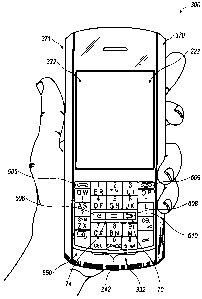
FIG. 1 illustrates a handheld wireless communication device configured
according
to the present teachings cradled in the palm of a user's hand;
FIG. 1A is a close-up of the keyfield employed on the device illustrated in
FIG. 1;
FIG. 2 is a block diagram representing a wireless handheld communication
device
interacting in a communication network;
FIG. 3A illustrates an examplary QWERTY keyboard layout;
FIG. 3B illustrates an examplary QWERTZ keyboard layout;
FIG. 3C illustrates an examplary AZERTY keyboard layout;
FIG. 3D illustrates an examplary Dvorak keyboard layout;
FIG. 4 illustrates a QWERTY keyboard layout paired with a traditional ten-key
keyboard;
2
CA 02646771 2012-04-17
FIG. 5 illustrates ten digits comprising the numerals 0-9 arranged in a
traditional,
ITU Standard E.161 numeric telephone keypad layout, including the * and # keys
flanking the 0 key;
FIG. 6 illustrates a traditional or standard phone key arrangement or layout
according to the ITU Standard E.161 including both numerals and letters;
FIG. 7 is an alternative embodiment of keyfield employed on a handheld
electronic communication device;
FIG. 8 is a schematic section view of a key configured to have dual input
functionality; and
FIG. 9 is a flow chart illustrating an examplary method for on-screen cursor
navigation instruction.
DETAILED DESCRIPTION
An examplary handheld wireless communication device 300 is shown in FIG. 1,
and the device's cooperation in a wireless network 319 is exemplified in the
block
diagram of FIG. 2. These figures are examplary only, and those persons skilled
in the art
will appreciate the additional elements and modifications necessary to make
the device
300 work in particular network environments.
As shown in the block diagram of FIG. 2, the handheld device 300 includes a
microprocessor 338 that controls the operation of the device 300. A
communication
subsystem 311 performs all communication transmission and reception with the
wireless
network 319. The microprocessor 338 further connects with an auxiliary
input/output
(1/0) subsystem 328, a serial port (preferably a Universal Serial Bus port)
330, a display
322, a keyboard 332, a speaker 334, a microphone 336, random access memory
(RAM)
326, and flash memory 324. Other communication subsystems 340 and other device
subsystems 342 are generally indicated as being functionally connected with
the
microprocessor 338 as well. An example of a communication subsystem 340 is
that of a
short range communication system such as BLUETOOTH communication module or a
Wi-Fi communication module (a communication module in compliance with IEEE
802.11b) and associated circuits and components. Additionally, the
microprocessor 338
is able to perform operating system functions and preferably enables execution
of
software applications on the handheld wireless communication device 300.
Furthermore,
the microprocessor 338 is communicatively interposed between alphabetic keys
of the
3
CA 02646771 2012-04-17
keyboard 332 and a display screen of the display area 322, and is configured
to receive
text input instructions via the alphabetic keys of the keyboard area and to
display
corresponding text on the display screen of the display area 322.
As will be explained more fully below, the auxiliary input system 328
according
to this disclosure is embedded in that it shares space with and overlaps the
keyfield area
650 generally used for text entry, as illustrated in FIGS. 1 and 1A. The
auxiliary input
system has a navigation initiation zone 70 from which navigation is initiated
and a cursor
navigation area 72 through which the user moves his finger to control motion
of a cursor,
pointer, icon, menu highlighting or the like across the display screen 322 of
the device
300. The navigation initiation zone 70 is bounded by coincidently located
alphabetic
keys 610 of the keyfield area 650 and the cursor navigation area 72. The
navigation
initiation zone 70 includes a navigation initiation key 74, but may also
include other
navigation-related buttons such as a menu key 606 and an escape or back key
608 to
facilitate interaction with the device if so desired. The cursor navigation
area 72 bounds
the navigation initiation zone 70 and overlies a number of the alphabetic keys
610 of the
keyfield area 650 on the device 300. Thus, the user navigates by dragging his
fingertip
over the keys of the keyfield area 650 that are otherwise ¨ generally, as
referenced above
¨ used for text entry. The user initiates navigation by actuating the
navigation initiation
key 74; this indicates to the device microprocessor 338 that the user is
navigating, as
opposed to moving between keys while typing, and ensures that subsequent
pressure on
or depression of keys of the keyfield area 650 is interpreted as part of the
navigational
input instead of textual input. The microprocessor 338 is programmed to
interpret cursor
guidance instructions from the sweeping contact motion that is initiated at
the navigation
initiation zone 70. As the sweeping motion continues across the cursor
navigation area
72, the microprocessor 338 is configured to receive cursor guidance
instructions via the
cursor navigation area 72 and to cause corresponding cursor movement on the
display
screen 322 of the display area 222. Furthermore, the microprocessor 338 is
programmed
to interpret text input instructions from contact that initiates at an
alphabetic key 610.
The device can be configured such that navigation is terminated in a variety
of ways,
including by pressing the navigation initiation key 74 a second time; by
pressing a text
key a certain number of times in a row (for example, two or three times); or
by a time-out
after a predetermined period of time (for example, two seconds) of no
activation of the
keyfield area 650.
4
CA 02646771 2012-04-17
In another exemplary embodiment, keys within the navigation initiation zone 70
may utilize a surface treatment on the key surface such that the top surface
of the key is
distinctive from the surface of other keys and which is tactilely perceptible.
The surface
treatments will be indicative of the permissible directions in which cursor
guidance can
initiate. In one embodiment, the indicated permissible directions include
horizontal and
vertical. In yet another embodiment, the indicated permissible directions
include
horizontal, vertical and diagonal directions. In yet another embodiment, the
indicated
permissible directions can include those listed above as well as other
directions.
Suitably, the navigation initiation key 74, in one example illustrated in FIG.
8, is
an actual or physical key configured for two levels of functionality. In
particular, it may
be configured with both "soft-press" attributes and "hard-press" attributes.
The soft-press
mode of actuation would be used to initiate navigation, whereas the hard-press
mode of
actuation would be used to make other entries into the device 300 (for
example, to select
a menu option, highlighted icon, and the like). The soft-press functionality
can be
provided by making the navigation initiation key 74 contact-sensitive, for
example,
through the use of a capacitance detector or a surface acoustic wave detector
on its upper
surface or through the use of pressure sensors which can sense the application
of pressure
to the navigation initiation key 74 in any direction. The hard-press
functionality, on the
other hand, can be provided by means of a dome switch located below the
navigation
initiation key 74. (Such dual functionality likely would not be present on a
"virtual" or
image-type navigation initiation key 74 that could be employed on devices
using one or
more LCD's to present to the user ¨ at least when the device is turned on ¨
the keyfield
area 650 as well as the main user interface display screen 322; in that case,
functionality
of the navigation initiation "button" would be limited to initiating
navigation.)
Similarly, depending on their basic construction (particularly in the case of
physical keys), the keys of the keyfield area 650, may be configured with dual
means of
actuation ¨ one means of actuation being provided to effect navigation and the
other
means of actuation being provided to effect text entry. For example, like a
physical
navigation initiation key, the keyfield keys may have both soft-press
functionality for
navigation (provided, for example, by capacitance or surface acoustic wave
detectors or
pressure sensors) and hard-press functionality for text entry (provided, for
example, by
dome switches). In that case, pressing the navigation initiation key 74 in the
manner that
activates device navigation indicates to the handheld device 300 which of the
two
5
CA 02646771 2012-04-17
keyfield input modalities to be activated or recognized. Alternatively, the
keys of the
keyfield area 650 may be constructed with just a single input modality. For
example, the
keys may be flush with the surface of the handheld device 300 and register
that they are
being pressed by capacitance or surface wave detectors, or they may be
"virtual" keys
that are presented to the user on an LCD display. In that case, pressing the
navigation
initiation key 74 in the manner that activates device navigation indicates to
the handheld
device 300 how to interpret the input signal from the keys of the keyfield
area 650 ¨ for
example, whether the user is navigating the display area 222 the handheld
device 300 or
making a textual entry into the handheld device 300. Additionally the
navigation
initiation key 74 may have a contact-sensitive top surface that is physically
depressible.
As may be appreciated from FIG. 1, one embodiment of a handheld wireless
communication device 300 comprises a lighted display 322 located above a
keyboard 332
constituting a user input and suitable for accommodating both textual input
and
navigational input to the handheld wireless communication device 300. The
front face
370 of the device 300 has a navigation initiation zone 70 and an at least
partially
surrounding the keyfield 650. The keyfield 650 may, as shown in FIGS. 1 and
la, include
alphabetic 610, alphanumeric 612, and other function keys 614. The keys of the
keyfield
area 650 may be physically depressible. Moreover, as shown in FIGS. 1 and 1 a,
the
alphabetic may be of a reduced keyboard design, in which multiple letters are
associated
with at least some of the keys. Alternatively, the alphabetic keys 610 and
alphanumeric
keys 612 may be of a full keyboard design, in which only one letter is
associated with any
given key. Regardless, however, of whether the keyboard is of a reduced or
full
configuration, the order of the letters of the alphabetic keys 610 or
alphanumeric keys 612
on the presently disclosed handheld device 300 can be described as being of a
traditional,
but non-ITU Standard E.161 layout. This terminology has been utilized to
delineate the
fact that such a telephone keypad as depicted in FIG. 6 may not allow for
efficient text
entry on the handheld device 300.
The handheld wireless communication device 300 is also configured to send and
receive voice communications such as mobile telephone calls. To facilitate
telephone
calls, two call keys 605, 609 are provided. One of the two call keys is a call
initiation key
605, and the other is a call termination key 609. In the navigation initiation
zone 70, the
menu key 606 is used to bring up a menu on the display screen 322 and the back
or
escape key 608 is used to return to the previous screen or previous menu
selection. The
6
CA 02646771 2012-04-17
functions of the call keys 605, 609 and the menu keys 606, 608 may, of course,
be
provided by buttons that are located elsewhere on the handheld device 300.
Furthermore, the handheld device 300 is equipped with components to enable
operation of various programs, as shown in FIG. 2. In an examplary embodiment,
the
flash memory 324 is enabled to provide a storage location for the operating
system 357,
device programs 358, and data. The operating system 357 is generally
configured to
manage other application programs 358 that are also stored in memory 324 and
executable on the processor 338. The operating system 357 honors requests for
services
made by application programs 358 through predefined application program 358
interfaces. More specifically, the operating system 357 typically determines
the order in
which multiple applications 358 are executed on the processor 338 and the
execution time
allotted for each application 358, manages the sharing of memory 324 among
multiple
applications 358, handles input and output to and from other device subsystems
342, and
so on. In addition, users can typically interact directly with the operating
system 357
through a user interface usually including the keyboard 332 and display screen
322.
While in an examplary embodiment the operating system 357 is stored in flash
memory
324, the operating system 357 in other embodiments is stored in read-only
memory
(ROM) or similar storage element (not shown). As those skilled in the art will
appreciate,
the operating system 357, device application 358 or parts thereof may be
loaded in RAM
326 or other volatile memory.
In one examplary embodiment, the flash memory 324 contains
programs/applications 358 for execution on the handheld device 300 including
an address
book 352, a personal information manager (PIM) 354, and the device state 350.
Furthermore, programs 358 and other information 356 including data can be
segregated
upon storage in the flash memory 324 of the handheld device 300.
When the handheld device 300 is enabled for two-way communication within the
wireless communication network 319, it can send and receive signals from a
mobile
communication service. Examples of communication systems enabled for two-way
communication include, but are not limited to, the General Packet Radio
Service (GPRS)
network, the Universal Mobile Telecommunication Service (UMTS) network, the
Enhanced Data for Global Evolution (EDGE) network, and the Code Division
Multiple
Access (CDMA) network and those networks, generally described as packet-
switched,
narrowband, data-only technologies which are mainly used for short burst
wireless data
7
CA 02646771 2012-04-17
transfer. For the systems listed above, the handheld wireless communication
device 300
must be properly enabled to transmit and receive signals from the
communication
network 319. Other systems may not require such identifying information. GPRS,
UMTS, and EDGE require the use of a Subscriber Identity Module (SIM) in order
to
allow communication with the communication network 319. Likewise, most CDMA
systems require the use of a Removable Identity Module (RUIM) in order to
communicate with the CDMA network. The RUIM and SIM card can be used in
multiple
different communication devices 300. The handheld communication device 300 may
be
able to operate some features without a SIM/RUIM card, but it will not be able
to
communicate with the network 319. A SIM/RUIM interface 344 located within the
device 300 allows for removal or insertion of a SIM/RUIM card (not shown). The
SIM/RUIM card features memory and holds key configurations 351, and other
information 353 such as identification and subscriber related information.
With a
properly enabled communication device 300, two-way communication between the
handheld wireless communication device 300 and communication network 319 is
possible.
If the handheld wireless communication device 300 is enabled as described
above
or the communication network 319 does not require such enablement, the two-way
communication enabled handheld device 300 is able to both transmit and receive
information from the communication network 319. The transfer of communication
can
be from the handheld device 300 or to the device 300. In order to communicate
with the
communication network 319, the handheld device 300 in the presently described
examplary embodiment is equipped with an integral or internal antenna 318 for
transmitting signals to the communication network 319. Likewise the handheld
wireless
communication device 300 in the presently described examplary embodiment is
equipped
with another antenna 316 for receiving communication from the communication
network
319. These antennae (316, 318) in another examplary embodiment are combined
into a
single antenna (not shown). As one skilled in the art would appreciate, the
antenna or
antennae (316, 318) in another embodiment are externally mounted on the
handheld
device 300.
When equipped for two-way communication, the handheld wireless
communication device 300 features a communication subsystem 311. As is well
known
in the art, this communication subsystem 311 is modified so that it can
support the
8
CA 02646771 2012-04-17
operational needs of the handheld device 300. The subsystem 311 includes a
transmitter
314 and receiver 312 including the associated antenna or antennae (316, 318)
as described
above, local oscillators (L0s) 313, and a processing module 320 which in the
presently
described examplary embodiment is a digital signal processor (DSP) 320.
It is contemplated that communication by the handheld device 300 with the
wireless network 319 can be any type of communication that both the wireless
network
319 and handheld device 300 are enabled to transmit, receive and process. In
general,
these can be classified as voice and data. Voice communication is
communication in
which signals for audible sounds are transmitted by the handheld device 300
through the
communication network 319. Data is all other types of communication that the
handheld
device 300 is capable of performing within the constraints of the wireless
network 319.
Example device applications that can depend on such data include email,
contacts
and calendars. For each such application synchronization with home-based
versions on
the applications can be critical for either or both of their long term and
short term utility.
As an example, emails are often time sensitive, so substantially real time
synchronization
is highly desirable. Contacts, on the other hand, can be usually updated less
frequently
without inconvenience. Therefore, the utility of the handheld device 300 is
significantly
enhanced (if not enabled) when connectable within a communication system, and
particularly when connectable on a wireless basis in a network 319 in which
voice, text
messaging, and other data transfer are accommodated.
As intimated hereinabove, one of the more important aspects of the handheld
wireless communication device 300 to which this disclosure is directed is its
size. While
some users will grasp the handheld device 300 in both hands, it is intended
that a
predominance of users will cradle the handheld device 300 in one hand in such
a manner
that input and control over the handheld device 300 can be effected using the
thumb of
the same hand in which the handheld device 300 is held. However, it is
appreciated that
additional control can be effected by using both hands. As a handheld device
300 that is
easy to grasp and desirably pocketable, the size of the handheld device 300
must be kept
commensurately small. Of the device's dimensions, limiting its width is
important for the
purpose of assuring cradleability in a user's hand. Moreover, it is preferred
that the width
of the handheld device 300 be maintained at less than eight centimeters
(approximately
three inches). Keeping the handheld device 300 within these dimensional limits
provides
a hand cradleable unit that users prefer for its usability and portability.
Limitations with
9
CA 02646771 2012-04-17
respect to the height (length) of the handheld device 300 are less stringent
when
considering hand-cradleability. Therefore, in order to gain greater size, the
handheld
device 300 can be advantageously elongated so that its height is greater than
its width, but
still remains easily supported and operated in one hand.
A potential drawback is presented by the small size of the handheld device 300
in
that there is limited exterior surface area for the inclusion of user input
and device output
features. This is especially true for the "prime real estate" on the front
face 370 of the
handheld device 300, where it is most advantageous to include a display screen
322 that
outputs information to the user. The display screen 322 is preferably located
above a
keyboard 332 that is utilized for data entry into the handheld device 300 by
the user. If
the screen 322 is provided below the keyboard 332, a problem occurs in that
viewing the
screen 322 is inhibited when the user is inputting data using the keyboard
332. Therefore
it is preferred that the display screen 322 be above the input area, thereby
solving the
problem by assuring that the hands and fingers do not block the view of the
screen 322
during data entry periods.
To facilitate textual data entry into the handheld device 300, an alphabetic
keyboard 332 is provided. In the exemplary illustrated embodiment, a reduced
format
alphabetic keyboard 332 is utilized in which there are multiple letters
associated with at
least some of the keys (with some of the letter keys also having numbers,
symbols, or
functions associated with them). In this regard, the letter indicia associated
with the
alphabetic keys can be advantageously organized in QWERTY, QWERTZ, AZERTY, or
Dvorak layouts, among others, thereby capitalizing on certain users'
familiarity with
these various letter orders. An exemplary arrangement is shown in FIGS. 1 and
la, where
indicia for the letter Q is located above the navigation initiation zone 70 on
the front face
of the body of the device and the indicia for the letter M is located below
the navigation
initiation zone 70 on the front face 370 of the body of the device 300.
As shown in FIG. 1, the handheld wireless communication device 300 is
cradleable in the palm of a user's hand. The handheld device 300 is provided
with a
keyboard 332 to enter text data and place telephone calls and a display screen
322 for
communicating information to the user. A connect/send key 605 is preferably
provided to
aid in the placement of a phone call. Additionally, a disconnect/end key 609
is provided.
The send key 605 and end key 609 preferably are located at the upper left and
right
comers of the keyfield, as shown, although many other locations may be
utilized.
CA 02646771 2012-04-17
The keyboard 332 includes a plurality of keys that can be of a physically
depressible nature such as actuable buttons, or they can be of a software
nature, typically
constituted by virtual representations of physical keys on a display screen
322 (referred to
herein as "virtual keys"). It is also contemplated that the user input can be
provided as a
combination of the two types of keys. Each key of the plurality of keys has at
least one
actuable action which can be the input of a character, a command or a
function. In this
context, "characters" are contemplated to exemplarily include alphabetic
letters, language
symbols, numbers, punctuation, insignias, icons, pictures, and even a blank
space. Input
commands and functions can include such things as delete, backspace, moving a
cursor
up, down, left or right, initiating an arithmetic function or command,
initiating a
command or function specific to an application program or feature in use,
initiating a
command or function programmed by the user and other such commands and
functions
that are well known to those persons skilled in the art. Further, depending on
the
application 358 or feature in use, specific keys can be enabled or disabled.
In the case of physical keys, all or a portion of the plurality of keys have
one or
more indicia representing character(s), command(s), functions(s), or a
combination
including one or more of character(s), command(s), and function(s) displayed
at on one or
more of their top surface (as illustrated in FIGS. 1 and 1A) and on the
surface of the area
adjacent the respective key. In the instance where the indicia of a key's
function is
provided adjacent the key, the indicia can be printed on the device cover
beside the key,
or in the instance of keys located adjacent the display screen 322.
Additionally, current
indicia for the key may be temporarily shown nearby the key on the screen 322.
In the case of virtual keys, the indicia for the respective keys are shown on
the
display screen 322, which in one embodiment each virtual key has a contact-
sensitive top
surface and is enabled by touching the display screen 322, for example, with a
stylus to
generate the character or activate the indicated command or function. Some
examples of
display screens 322 capable of detecting a touch include resistive,
capacitive, projected
capacitive, infrared and surface acoustic wave (SAW) touchscreens.
Physical and virtual keys can be combined in many different ways as
appreciated
by those skilled in the art. In one embodiment, physical and virtual keys are
combined
such that the plurality of enabled keys for a particular application or
feature of the
handheld wireless communication device 300 is shown on the display screen 322
in the
same configuration as the physical keys. Using this configuration, the user
can select the
11
CA 02646771 2012-04-17
appropriate physical key corresponding to what is shown on the display screen
322.
Thus, the desired character, command or function is obtained by depressing the
physical
key corresponding to the character, command or function displayed at a
corresponding
position on the display screen 322, rather than touching the display screen
322.
The various characters, commands, and functions associated with keyboard
typing
in general are traditionally arranged using various conventions. The most
common of
these in the United States, for instance, is the QWERTY keyboard layout.
Others include
the QWERTZ, AZERTY, and Dvorak keyboard configurations. The QWERTY keyboard
layout is the standard English-language alphabetic key arrangement 44a shown
in FIG. 3a
and is employed in the exemplary embodiment illustrated in FIG. 1. The QWERTZ
keyboard layout is normally used in German-speaking regions; this alphabetic
key
arrangement 44b is shown in FIG. 3b. The AZERTY keyboard layout 44c is
normally
used in French-speaking regions and is shown in FIG. 3c. The Dvorak keyboard
layout
was designed to allow typists to type faster; this alphabetic key arrangement
44d is shown
in FIG. 3d. In other examplary embodiments, keyboards having multi-language
key
arrangements can be implemented.
Alphabetic key arrangements are often presented along with numeric key
arrangements. Typically, the numbers 1-9 and 0 are positioned in the row above
the
alphabetic keys 44a-d, as shown in FIG. 3a-d. Alternatively, the numbers share
keys with
the alphabetic characters, such as the top row of the QWERTY keyboard. Yet
another
examplary numeric key arrangement is shown in FIG. 4, where a "ten-key" style
numeric
keypad 46 is provided on a separate set of keys that is spaced from the
alphabetic/numeric
key arrangement 44. Further, a split numeric phone key arrangement 242 is
exemplarily
illustrated in FIGS. 1 and I a, where the numbers 1-3 and 4-6 are located in
rows above
the navigation initiation zone 70 and the numbers 7-9 and 0 are located in
rows blow the
navigation initiation zone 70.
As shown in FIG. 5, the numeric phone key arrangement 42 may also utilize a
surface treatment on the surface of the "5" key. This surface treatment is
configured such
that the top surface of the key is distinctive from the surface of other keys.
Preferably
the surface treatment is in the form of a raised bump or recessed dimple 43.
Alternatively, raised bumps may be positioned on the housing 76 around the "5"
key and
do not necessarily have to be positioned directly on the key.
12
CA 02646771 2012-04-17
It is desirable for handheld devices 300 to include a combined text-entry
keyboard
and a telephony keyboard, as illustrated in FIGS. 1 and la. Examples of such
handheld
devices 300 include mobile stations, cellular telephones, wireless personal
digital
assistants (PDAs), two-way paging devices, and others. Various keyboard
arrangements
can be used with such devices and can be termed a full keyboard, a reduced-
format
keyboard (as illustrated), or phone key pad. In embodiments of a handheld
device 300
having a full keyboard, the alphabetic characters are singly associated with
the plurality
of physical keys. Thus, in an English-language keyboard of this configuration,
there
would be at least 26 keys in the plurality, with one letter per alphabetic
key.
FIGS. 5 and 6 both feature numeric keys arranged according to the ITU Standard
E.161 form. In addition, FIG. 6 also incorporates alphabetic characters
according to the
ITU Standard E.161 layout as well. The International Telecommunications Union
("ITU") has established phone standards for the arrangement of alphanumeric
keys. The
standard phone numeric key arrangement shown in FIGS. 5 (no alphabetic
letters) and 6
(with alphabetic letters) corresponds to ITU Standard E.161, entitled
"Arrangement of
Digits, Letters, and Symbols on Telephones and Other Devices That Can Be Used
for
Gaining Access to a Telephone Network." This standard is also known as ANSI
TI.703-
1995/1999 and ISO/IEC 9995-8:1994. As shown in FIGS. 1 and la, the numeric key
arrangement can be overlaid on a QWERTY arrangement. The numeric arrangement
as
shown can be aptly described as a top-to-bottom ascending order three-by-three-
over-zero
pattern.
While several keyboard layouts have been described above, the layouts can be
described as having keys disposed on the keyboard in a QWERTY, reduced QWERTY,
QWERTZ, Dvorak, or AZERTY key layout. These familiar keyboard layouts allow
users
to type more intuitively and quickly than, for example, on the standard
alphabetic layout
on a telephone pad. As mentioned above, the key arrangements can be reduced
compared
to a standard layout through the use of more than one letter or character per
key. By
utilizing fewer keys, the keys can be made larger and therefore more
convenient to the
user.
Reverting now to a more detailed discussion of the focus of this disclosure, a
preferred arrangement for navigating a handheld wireless device 300 is
disclosed in
FIGS. 1, la, and 7-8. As summarized above, a preferred keyboard arrangement
includes
a initiation zone 70 from which navigation is initiated and a cursor
navigation area 72
13
CA 02646771 2012-04-17
through which the user moves his finger or other object or digit to control
motion of a
cursor, pointer, icon, menu highlighting or the like across the display screen
322. The
navigation initiation zone 70 is bounded at least partially by the
coincidently located
portions of the alphabetic keys 610 and cursor navigation area 72 and includes
a
navigation initiation key 74. The navigation initiation zone 70 may also
include other
navigation-related keys such as a menu key 606 and an escape or back key 608
to
facilitate interaction with the device if so desired. In at least one
embodiment, the
navigation initiation zone 70 includes a physically depressible key 210, which
may have a
contact-sensitive top surface. The navigation initiation zone 70 may include a
plurality of
input keys, for example the menu 606, navigation initiation key 74, escape key
608 and
other keys. This plurality of input keys within the navigation initiation zone
70 may also
have contact-sensitive top surfaces. Additionally, the plurality of input keys
can be a
physically depressible key with a contact-sensitive top surface. Furthermore,
in addition
to initiating navigation, the navigation initiation zone 70 may also serve as
a wakeup
actuator for the cursor navigation area 72 from an energy-saving sleep mode.
The cursor navigation area 72 bounds the navigation initiation zone 70 and
overlies a number of the text entry keyfield keys on the device. The cursor
navigation
area 72 is illustrated with broken lines to indicate that its bounds may vary
in size, for
example, depending on the application being run on the device, size of the
keyfield area
650 and the like. Furthermore, the cursor navigation area 72 may completely
surround
the navigation initiation zone 70, as illustrated, although complete
encirclement is not
necessary for implementation of a device according to this disclosure. Rather,
bounding
¨ whether partial or total ¨ is sufficient. In operation of the device 300,
the user navigates
by dragging his fingertip over the keys of the keyfield 650 that can be used
for text entry.
The user initiates navigation by actuating the navigation initiation key 74;
this indicates to
the device microprocessor 338 that the user is navigating, as opposed to just
moving
between keys while typing, and ensures that subsequent pressure on or
depression of
keyboard keys 332 is interpreted as part of the navigational input instead of
text input.
As further noted above, the navigation initiation key 74 is suitably an actual
or
physical key (as opposed to a screen-presented depiction of a key) that is
configured for
dual levels of actuation. Such a configuration is illustrated in FIG. 8. As
illustrated, the
navigation initiation key 74 includes a contact-sensitive layer 78 on the
upper surface of
the body 80 of the key. The contact-sensitive layer 78 may be a capacitance
sensor, a
14
CA 02646771 2012-04-17
surface acoustic wave sensor, a pressure transducer, or any other suitable
means for
sensing when a user touches (and possibly applies light pressure to) the top
of the
navigation initiation key 74. Electrical leads (not shown) from the contact-
sensitive layer
78 may extend through the body 80 of the key and connect to the printed
circuit board 82
in suitable fashion. Furthermore, a dome switch 84 may be located on the
printed circuit
board 82 beneath the key 74 in known fashion. By pressing the key 74
sufficiently to
collapse the dome switch 84, the user enters a second level of input into the
device 300,
for example, in a manner analogous to making a mouse click to make an entry or
selection as noted above.
In the illustrated embodiment, the navigation initiation key 74 is dedicated
to the
navigation-initiation function. In alternate embodiments in which the
navigation
initiation key 74 is configured with dual modes of input, however, it could
also function
as a text entry key in addition to being used to initiate navigation.
Moreover, as noted above and particularly where they are physical or actual
keys,
the alphabetic keys 610 of keyfield area 650 may also be configured for dual
input entry ¨
one level of input being used for text entry and another level of input being
used for
navigation. There, the construction of the text entry keys of keyfield area
650 would be
essentially the same as shown in FIG. 8 for the navigation initiation key 74.
In that case,
actuation of the navigation initiation key 74 in a manner that tells the
device 300 the user
is about to navigate renders the contact-sensitive portions of the keys of
keyfield area 650
operable. Alternatively, if the keys of key-field area 650 are configured for
just a single
mode of actuation ¨ for example, if they include dome switches but no contact-
sensitive
upper surfaces or if they are virtual keys ¨ actuation of the navigation
initiation key 74 in
a manner that tells the device 300 the user is about to navigate will cause
the device 300
to interpret subsequent actuations of the alphabetic keys 610 of keyfield area
650 as
indicating navigation around the device 300.
The arrangement and construction of the alphabetic keys 610 can be according
to
the above description. Furthermore, in at least one embodiment each of the
alphabetic
keys 610 is a physically depressible key. In yet another embodiment, each of
the
alphabetic keys 610 is a virtual key having a contact sensitive top surface.
Additionally,
the letter indicia associated with the alphabetic keys can be arranged in a
QWERTY
layout. In one example as illustrated in FIGS. 1 and 1A, the indicia for the
letter Q is
located above the navigation initiation zone 70 on the front face 370 of the
body 371 of
CA 02646771 2012-04-17
the device 300 and the indicia for the letter M is located below the
navigation initiation
zone 70 on the front face 370 of the body 371 of the handheld device 300.
In another embodiment is presented in FIG. 7, which makes use of the above
described keyboard arrangement including an initiation zone 470 from which
navigation
is initiated and a cursor navigation area 472 through which the user moves his
finger or
other object or digit to control motion of a cursor, pointer, icon, menu
highlighting or the
like across the display screen 322. The navigation initiation zone 470 is
bounded at least
partially by the coincidently located portions of the alphabetic keys 410, 420
and cursor
navigation area 472 and includes a navigation initiation key 474. The
alphabetic keys are
divided into a right zone of alphabetic keys 410 and a left zone of alphabetic
keys 420.
The navigation initiation zone 470 may also include other navigation-related
keys such as
a menu key 606 and an escape or back key 608 to facilitate interaction with
the device if
so desired. The navigation initiation zone 470 may include a plurality of
input keys, for
example the menu 606, navigation initiation key 474, escape key 608 and other
keys.
This plurality of input keys within the navigation initiation zone 470 may
also have
contact-sensitive top surfaces. Additionally, the plurality of input keys can
be a
physically depressible key with a contact-sensitive top surface. Furthermore,
in addition
to initiating navigation, the navigation initiation zone 470 may also serve as
a wakeup
actuator for the cursor navigation area 472 from an energy-saving sleep mode.
The
functioning of the cursor navigation area 472 is similar to that as described
above with the
functionality differing in the arrangement of the initiation zone 470 which is
vertically
arranged rather than horizontally arranged as the initiation zone 70 of FIGS.
1 and 1A.
Furthermore, the keys are arranged such that six columns of alphabetic keys
are provided.
In the illustrated embodiment, the keyboard arrangement is a reduced keyboard
arrangement where more than one alphabetic character is presented on at least
one key.
In other embodiments, the keyboard can be a full keyboard arrangement such
that only
one alphabetic character is provided on each key. While in yet another
embodiment,
numeric characters can be provided in addition to the alphabetic characters.
The numeric
characters can be provided on either the right zone of alphabetic keys 410 or
the left zone
of alphabetic keys 420. When the keyboard arrangement is a full keyboard
arrangement,
the numeric characters can be provided on the keys as well. In a preferred
embodiment,
the numeric characters are arranged in a telephone layout, as described above.
16
CA 02646771 2012-04-17
While the navigation initiation zone 70 has generally been illustrated on the
front
face of the device, it can be similarly situation on other parts of the
device. For example
the navigation initiation zone can be located on one of the sides of the
device or the back
of the device. When located on the back of the device, the navigation
initiation zone can
function very similar to the above described embodiments. However, in at least
one
embodiment, the functionality of the surrounding navigation area is modified
such that
cursor navigation is effected on the display screen based upon motion
actuation by the
operator in the same direction.
In an exemplary embodiment, a computer program will be configured to run on a
microprocessor 338 in the handheld electronic communication device 300, and
will
distinguish between desired cursor navigation or text entry on the handheld
electronic
communication device 300. The computer program will be programmed to receive
data
indicative of a sensed sweeping contact motion that is initiated at a
navigation initiation
zone 70 and which continues across a cursor navigation area 72 on a front face
of the
device. This cursor navigation area 72 being located coincidently with at
least a portion of
a plurality of alphabetic keys on a front face of the device 300, and where
the device 300
includes a display screen 322 of the display area 222 located above a keyfield
area 650.
Furthermore, the microprocessor 338 being communicatively interposed between
the
cursor navigation area 72 of the keyboard and the display screen 322 of the
display area
222 may be further programmed to receive cursor guidance instructions via the
cursor
navigation area 72, and to cause cursor movement on the display screen 322 of
the
display area 222 in correspondence with the sensed sweeping contact motion
across the
cursor navigation area 72. In a further embodiment, the computer program
configured to
run on a microprocessor 338 in the handheld electronic communication device
300, will
be further configured to receive data that is indicative of a sensed initial
contact with an
alphabetic key 610. Additionally, the microprocessor 338 may be programmed to
receive
key-selection instructions via the keyfield and be further programmed to cause
at least
one corresponding letter associated with the contacted key to be displayed on
the display
screen 322 of the display area 222.
In at least one embodiment as illustrated in FIG. 9, a method 100 for
executing
cursor navigation or text entry on a handheld electronic communication device
300. In
the case of cursor navigation, the method first involves a user executing
sweeping contact
motion initiated at a navigation initiation zone 70 (block 102). This sweeping
contact
17
CA 02646771 2012-04-17
motion continues across a cursor navigation area 72 located coincidently with
at least a
portion of a plurality of alphabetic keys on a front face 370 of the device
300, and where
the device 300 includes a display screen 322 of the display area 222 located
above a
key-field area 650. Additionally, the method senses the sweeping contact
motion across
the cursor navigation area 72 by one of the above described devices or means
or
combination thereof (block 104). Data indicative of this sensed motion is
inputted to a
microprocessor 338 that is communicatively interposed between the cursor
navigation
area and the display screen 322 of the display area 222 (block 106). The
microprocessor
338 is programmed to receive and process this cursor guidance instruction data
via the
cursor navigation area 72, cause cursor movement on the display screen 322 of
the
display area 222 in correspondence with the sensed sweeping contact motion
that occurs
across the cursor navigation area 72 (block 108). In the case of text entry,
the method
first involves a user executing an initial contact with one of the alphabetic
keys of the
keyfield. The method then senses this initial contact with one of the
alphabetic keys by
one of the above described devices, means, or some combination thereof, and
data
indicative of the contacted key is then inputted to a microprocessor 338 that
is
communicatively interposed between the keyfield area and the display screen of
the
display area 322. Then, a microprocessor 338 programmed to receive and process
key-selection instructions via the keyfield, will then cause at least one
corresponding
letter associated with the contacted key to be displayed on the display screen
of the
display area 322.
Examplary embodiments have been described hereinabove regarding both
handheld wireless communication devices 300, as well as the communication
networks
319 within which they operate. Again, it should be appreciated that the focus
of the
present disclosure is providing a navigation initiation zone and an associated
cursor
navigation area, which are capable of interpreting the input as textual input
or cursor
navigation input. The above-described implementations are intended to be
examples
only. Alterations, modifications and variations can be effected to the
particular
embodiments by those of skill in the art without departing from the scope,
which is
defined solely by the claims appended hereto.
18