Note: Descriptions are shown in the official language in which they were submitted.
CA 02646818 2008-09-23
WO 2007/126891 PCT/US2007/007685
VISION INSPECTION SYSTEM DEVICE AND METHOD
BACKGROUND OF THE INVENTION
The present invention generally relates to a machine vision inspection device.
More
particularly, the present invention pertains to a machine vision inspection
device for use with a
composite material placement system.
Composite items are generally constructed from layers of material that are
laminated together.
These layers are often referred to as partial or full plies. For structures
exceeding the available
material width, each layer is typically made up of a series of strips or
courses of material placed edge
to edge next to each other or are overlapped to some extent. Each ply may be
in the form of woven
fibers in a fabric, unidirectional fiber material; metal foils, adhesive films
or a variety of other
conformations. Unidirectional fiber material is often termed, "tape." The
fibers may be made from
any of a multitude of natural and/or "man-made" materials such as fiberglass,
graphite, Kevlar , and
the like.
The courses are generally laid upon the form or tool in a specific pattern.
Deviations from this
pattern may result in unacceptable wrinkles, twist, gaps and/or overlap of the
courses. Other errors
that may occur during ply placement include foreign objects, such as, bits of
backing material or
debris ("blobs") becoming stuck to the surface of the tool or course. Blobs
generally include bits of
resin and stray fibers pulled from the tape that may ball up into "fuzz balls"
or fiber wads.
In these and other instances, if the error is not identified and corrected
prior to placement of
the next ply, material properties of the completed composite item may be
adversely affected.
Conventionally, technicians have been employed to inspect the courses. This
typically involves
stopping course placement while the inspection occurs to insure thorough
inspection and minimize
risk to the technicians. Accordingly, inspection greatly increases the
fabrication time and expense of
the composite item. In an attempt to assist the inspection technicians,
conventional machine vision
systems have been utilized in the inspection process. However, these
conventional machine vision
systems are not capable of identifying all of the various types of anomalies.
Nor are they capable of
inspecting at the laydown rates currently achievable with multi-head tape
lamination machines.
Accordingly, it is desirable to provide a method and apparatus capable of
overcoming the
disadvantages described herein at least to some extent.
=
1
CA 02646818 2013-11-13
SUMMARY OF THE INVENTION
The foregoing needs are met, to a great extent, by the present invention,
wherein in one
respect an apparatus and method is provided that in some embodiments
identifies errors on placed
plies.
An embodiment of the invention provides a system to inspect a course material
applied to a
substrate during fabrication of a composite item, the system comprising: a
vision assembly
comprising: an area light to illuminate an area of the course material; a line
generator to generate a
line of illumination across the area; a sensor to capture an image of the
area; and an image
processor to analyze the image, wherein the image processor is configured to
identify debris on the
course material in response to the area light being activated and the image
processor is configured
to identify placement aberrations in response to the line generator being
activated.
Another embodiment of the present invention pertains to an apparatus for
inspecting a
course material applied to a substrate during fabrication of a composite item.
The apparatus
includes a means for diffusely illuminating an area of the course material, a
means for generating a
line of illumination across the area, means for capturing an image of the
area, and a means for
analyzing the image. The image is analyzed to identify debris on the course
material in response to
diffusely illuminating the area and the image is analyzed to identify
placement aberrations in
response to the line of illumination.
Yet another embodiment of the present invention provides a method of
inspecting a course
material applied to a substrate during fabrication of a composite item, the
method comprising:
diffusely illuminating an area of the course material; generating a line of
illumination across the
area; capturing an image of the area; and analyzing the image, wherein the
image is analyzed to
identify debris on the course material in response to diffusely illuminating
the area and the image is
analyzed to identify placement aberrations in response to the line of
illumination.
There has thus been outlined, rather broadly, certain embodiments of the
invention in order
that the detailed description thereof herein may be better understood, and in
order that the present
contribution to the art may be better appreciated. There are, of course,
additional embodiments of
the invention that will be described below and which will form the subject
matter of the claims
appended hereto.
In this respect, before explaining at least one embodiment of the invention in
detail, it is to
be understood that the invention is not limited in its application to the
details of construction and to
the arrangements of the components set forth in the following description or
illustrated in the
drawings.
2
CA 02646818 2008-09-23
WO 2007/126891 PCT/US2007/007685
The invention is capable of embodiments in addition to those described and of
being practiced and
carried out in various ways. Also, it is to be understood that the phraseology
and terminology
employed herein, as well as the abstract, are for the purpose of description
and should not be regarded
as limiting.
As such, those skilled in the art will appreciate that the conception upon
which this disclosure
is based may readily be utilized as a basis for the designing of other
structures, methods and systems
for carrying out the several purposes of the present invention. It is
important, therefore, that the
claims be regarded as including such equivalent constructions insofar as they
do not depart from the
spirit and scope of the present invention.
BRIEF DESCRIPTION OF THE DRAWINGS
FIG. 1 is a block diagram of a multi-head tape lamination system according to
an embodiment
of the invention. =
FIG. 2 is a perspective view of the multi-head tape lamination system
according to an
embodiment of the invention.
FIG. 3 is a side view of a head and vision assembly suitable for use with the
multi-head tape
lamination system of FIG. 1.
FIG. 4 is a rear view of the vision assembly and head suitable for use with
the multi-head tape
lamination system of FIG. 1.
FIG. 5 is a block diagram of a vision controller suitable for use with the
multi-head tape
lamination system of FIG. 1.
FIG. 6 is a flow diagram illustrating steps of a method in accordance with an
embodiment of
the invention.
DETAILED DESCRIPTION OF THE PREFERRED EMBODIMENT
The present invention provides, in some embodiments, an in-process, machine
vision,
inspection system for a composite placement device and a method of using this
system. In various
embodiments, the system is suitable for use with an automated lamination
device such as, for
example, an automated fiber placement (AFP) machine, flat tape lamination
machine (FTLM),
numerically controlled (NC) contoured tape lamination machine (CTLM), multi-
head tape lamination
machine (MHTLM), and the like. These automated lamination devices generally
include at least one
placement head or "head" to place plies of composite material upon a mandrel,
layup mold or tool to
fabricate a composite item. The MHTLM may include a plurality of such heads.
In an embodiment,
3
CA 02646818 2008-09-23
WO 2007/126891 PCT/US2007/007685
the system includes a machine vision inspection assembly associated with each
dispensing head of the
MHTLM.
The invention will now be described with reference to the drawing figures, in
which like
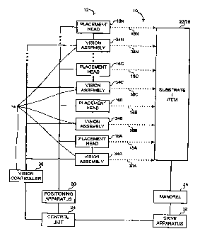
reference numerals refer to like parts throughout. As shown in FIG. 1, a multi-
head tape lamination
system ("MHTLS") 10 suitable for use in an embodiment of the invention
includes a multi-head tape
lamination machine ("MHTLM") 12 and a machine-vision inspection system
("MVIS") 14. The
MHTLM 12 includes one or more heads 16a-16n to place 18 a course 20 (shown in
FIG. 2) upon a
substrate 22. This substrate 22 includes a surface of a mandrel 24 and/or any
previously placed
courses 20. By placing courses 20 on the substrate 22 in this manner, an item
26 is generated. In
= addition, the MHTLM 12 includes a controller 28 to control a positioning
device 30 and/or a drive
apparatus 32. The positioning device 30 positions the heads 16a-16n relative
to the substrate 22. The
drive apparatus 32 positions or rotates the mandrel 24 upon which the
substrate 22 is affixed.
The MVIS 14 includes at least one vision assembly 34a-34n and a vision
controller 36. In an
embodiment, each of the heads 16a-16n includes a respective vision assembly
34a-34n. As described
herein, the vision assemblies 34a-34n are configured to inspect 38 the placed
18 courses 20.
FIG. 2 is a perspective view of the MHTLM 12 according to an embodiment of the
invention.
As shown in FIG. 2, the MHTLM 12 includes a frame 40 to position the placement
heads 16a-16d
relative to the substrate 22. The frame 40 and substrate 22 are configured to
move in directions A and
B relative to one another. In this manner, some or all of the placements heads
16a-16d are configured
to place respective courses 20 or strips of a composite tape upon the
substrate 22. Each course 20
includes any suitable material to fabricate the item 26. Examples of suitable
materials include metal
foils, films, fibers, and the like. These materials may be coated or
impregnated with resin. In a
particular example, the course 20 includes carbon fibers that are pre-
impregnated with a thermoset
resin (pre-preg). In another example, the course 20 includes a titanium foil
that is coated with a resin.
The composite item 26 includes any suitable item or part that may be
fabricated with the course 20.
Particular examples include wing and fuselage components for an aircraft.
Other examples include
car and truck body and framing members and various other consumer products.
Increasing the number of heads 16a-16n employed in the fabrication of the item
26 increases
the fabrication rate. Thus, by increasing the number of heads 16a-16n, the
item 26 may be produced
in less time and/or more economically. However, during placement of the
courses 20, the head 16a is
operable to pivot about any suitable number of axes. For example, the head 16a
may pivot about 1 to
6 or more axes depending upon the shape of the item 26 being fabricated. As
such, if too many heads.
4
CA 02646818 2008-09-23
WO 2007/126891 PCT/US2007/007685
16a-16n are placed upon the frame 40, the heads 16a-16n may interfere with one
another. In this
regard, the MHTLS 10 includes a respective operational envelope 42a-42n for
each head 16a-16n.
For the sake of simplicity, the operational envelope 42a will be described
herein and it is to be
understood that the operational envelopes 42b-42n are of a similar nature. The
operation envelope
42a defines a volume within which the head 16a operates. The operational
envelope 42a is
configured to avoid interference between the head 16a and any structure in the
proximity of the head
16a. These structures include the frame 40, heads 16b-16n, substrate 22, and
the like. For example,
by disposing the heads 16a-16n such that the respective operational envelopes
42a-42n do not
overlap, interactions between the heads 16a-16n, such as "head crashes," are
minimized. It is an
advantage of an embodiment of the invention that, the vision assembly 34a fits
within the operational
envelope 42a.
Of note, although four heads 16a-16d are depicted in FIG. 2, the various
embodiments of the
MHTLS 10 may include any suitable number of heads 16a-16n. For Example, 2,4,
8, 16, and 32 or
more heads 16a-16n are suitable for use with the MHTLS 10. In addition, heads
16a-16n may be
added or removed as indicated to fabricated the item 26. In this regard, it is
an advantage of an
embodiment of the invention that, because a respective vision assembly 34a-34n
is associated with
each head 16a-16n, as the heads 16a-16n are added or removed, the associated
vision assembly 34a-
34n is added or removed as well.
FIG. 3 is a side view of the head 16a and vision assembly 34a suitable for use
with the
MHTLS 10 of FIG. 1. As shown in FIG. 3, the head 16a includes a supply reel 50
to supply a tape 52.
The tape 52 is threaded along a tape path 54. The head 16a further includes a
take-up reel 56 to
retain an option backing 58 that may be removed from the tape 52. The head 16a
further includes a
compaction roller 60 to compact or consolidate the tape 52 upon the substrate
22 (shown in FIG. 2).
As shown in FIG. 3, the head 16a includes the vision assembly 34a. The vision
assembly 34a
includes a sensor 62 and lighting system 64. In an embodiment, the lighting
system 64 includes one
or more area lights 66 and a laser 68. In general, the area lights 66
illuminate a generalized area and
may facilitate sensing foreign objects on the course 20. The laser 68
generates a line of illumination
across the course 20 and may facilitate sensing misalignments, overlaps, gaps,
and the like in course
placement. The vision assembly 34a optionally includes an encoder 70, encoder
drive 72, and belt 74.
In operation, the head 16a is guided in direction "C" along a path via the
various movements
of the frame 40 and the mandrel 24 and is configured to place the tape 52 upon
the substrate 22. The
tape 52 and the substrate 22 are configured to adhere to one another. For
example, the tape 52 and/or
CA 02646818 2008-09-23
WO 2007/126891 PCT/US2007/007685
the substrate 22 may be tacky. The compaction roller 60 is configured to press
or urge the tape 52
towards the substrate 22 so as to consolidate the tape 52 into the layup. The
vision assembly 34a is
configured to sense this placed tape 52, the position of the placed tape
relative to any adjacent tape 52
(e.g., a previously applied course 20 and the like), and/or any foreign object
that may be present on
the surface of the tape 52.
The encoder 70, if present, is configured to sense movement of the compaction
roller 60
and/or the head 16a and output a signal in response to the sensed movement. In
a particular example,
the encoder drive 72 may mate with or engage the compaction roller 60 so as to
move in response to
movement of the compaction roller 60. The belt 74 is configured to translate
movement of the
encoder drive 72 to the encoder 70. In other examples, the encoder 70 may
directly engage the
encoder drive 72 and/or compaction roller 60 or the encoder 70 may be linked
to the encoder drive 72
via a shaft or other such linking mechanism. If not present, the actions of
the encoder 70, encoder
drive 72, and belt 74 may be subsumed by a processor, such as the controller
28, that may be
configured to generate signals in response to movement instruction or sensed
movements performed
by the MHTLS 10.
FIG. 4 is a rear view of the vision assembly 34a and head 16a suitable for use
with the
MHTLS 10 of FIG. 1. As shown in FIG. 4, the vision assembly 34 optionally
includes a mirror 80
and a marker 82. If included, the mirror 80 is configured to reflect or
redirect light, or other such
forms of electromagnetic radiation, towards the sensor 62. In this manner,
illumination from the
lighting system 64 may be configured to strike the course 20 at a relatively
low angle and the sensor
62 may be configured to view the course 20 from a relatively higher angle. The
relatively low
incident angle of the lighting system 64 facilitates a variety of advantages.
For example, having the
area lights 66 disposed relatively near the course 20 and/or casting light
substantially across the
course 20 facilitates casting a longer shadow in response to striking a
foreign object present on the
course 20. In another example, the laser 68 may be disposed at a relatively
low incident angle and
configured to generate a line 84, or a plurality of lines 84, across the
course 20. In this manner,
relatively small deviations in the height of the course 20 generate relatively
large deviations in the line
84 when viewed or sensed from a relatively high incident angle. For this
reason, the mirror 80 may be
disposed to redirect light from this relatively high incident angle towards
the sensor 62. In other
instances, the sensor 62 may be disposed to directly view the course 20 from a
relatively higher angle
and the mirror 80 and/or other reflective surface or redirecting device may be
omitted.
6
CA 02646818 2008-09-23
WO 2007/126891 PCT/US2007/007685
The marker 82, if present, is configured to place or deposit an indicator upon
the course 20. In
an embodiment, the indicator is placed in response to a sensed flaw. For
example, in response to
sensing that a foreign object is present on the course 20, the marker 82 may
be controlled to deposit
the indicator on or near the foreign object. In this regard, the marker 82 may
include any suitable
marking device for generating an indicator upon the course 20. Examples of
marking devices include
ink or paint sprayers, pens, and the like.
FIG. 5 is a block diagram of the vision controller 36 suitable for use with
the MHTLS 10 of
FIG. 1. As shown in FIG. 5, the vision controller 36 is configured to receive
signals from a pulse
counter 88. The pulse counter 88 generally acts as a switch to control the
lighting system 64. The
pulse counter 88 is configured to receive signals corresponding to movement or
rate of movement. In
a particular example, the pulse counter 88 is configured to receive signals
from the encoder 70 in
response to movement of the compaction roller 60. In this example, as the rate
of movement or
rotation of the compaction roller 60 changes, the signals received by the
pulse counter 88 are modified
accordingly. In response, the pulse counter 88 is configured to generate
signals to control the area
lights, laser 68, and/or a frame grabber 90. For example, the pulse counter 88
is configured to control
the area lights 66 and the laser 68 to turn on and illuminate the course 20 or
to turn off. In various
embodiments, the area lights 66 and the laser 68 may be controlled to turn on
and off in an alternating
fashion, to turn on and off simultaneously, to turn on and off independently,
or to turn on essentially
while the course 20 is being placed.
The vision controller 36 may include a processor 92, code 94, file 96, memory
98, clock 100,
and the like. The processor 92 is configured to execute computer readable code
such as the code 94.
According to the code 94, the processor 92 is configured to receive signals
from the pulse counter 88,
forward and receive signals to and from the frame grabber 90, process images
received from the frame
grabber 90, store and retrieve information to and from the file 96 and memory
98, receive time signals
from the clock 100 and the like. The file 96 is configured to store one or
more of the following:
positional information; time stamps; error codes; and the like.
FIG. 6 illustrates steps involved in a method 110 of inspecting the courses 20
placed on the
substrate 22. Prior to the initiation of the method 110, a composite product,
such as the item 26, is
designed and, based on this design, a series of computer readable instructions
specifying attributes of
the composite product is generated. In addition, the MHTLS 10 is prepared for
operation. These
preparations may include, for example, generating the mandrel 24 based on the
item 26, installing the
7
CA 02646818 2008-09-23
WO 2007/126891 PCT/US2007/007685
supply reels 50, threading the tape 52 along the tape path 54, powering the
MHTLS 10, calibrating the
various systems, and the like.
At step 112, the MHTLS 10 is initiated. For example, the controller 28 may
control the
positioning device 30 and drive apparatus 32 to move relative to one another.
In this manner, the
heads 16a-16n may be controlled to engage and proceed along the substrate 22.
At step 114, movement may be sensed. For example, movement of the compaction
roller 60
may be sensed and utilized at an indicator that the course 20 is being applied
to the substrate 22. In
particular, the encoder drive 72 may be rotated as a result of contact with
the compaction roller 60, the
rotation of the encoder drive 72 may, in turn, cause the belt 74 to rotate,
and the rotation of the belt 74
may modulate the encoder 70. In response to modulation, the encoder 70 may
forward a signal to the
pulse counter 88 and/or a controller such as the vision controller 36. For
example, the encoder 70
may generate a signal or pulse in response to a predetermined increment of the
tape 52 being placed
upon the substrate 22. The predetermined increment may include any suitable
value such as, 1 inch
(25.4rrun), 0.1 inch (2.54mm), 0.01 inch (0.254 mm), 0.001 inch (0.0254rrun),
and the like.
It is an advantage of an embodiment that the MVIS 14 dynamically responds to
changes in
laydown rates. For example, in response to the head 16a placing the tape 52 at
a faster rate, the
encoder 70 may be induced to generate signals at a similarly faster rate. As
described herein, in this
manner, the MVIS 14 is operable to dynamically modulate the frequency of
inspection.
In another embodiment, movement instructions for the mandrel 24 and/or the
positioning
device 30 may be utilized to sense or determine that movement has occurred or
the tape 52 has been
dispensed.
At step 116, the lighting system 64 may be modulated. In an embodiment, the
lighting system
64 may be alternated between the area lights 66 and the laser 68. That is,
either the area lights 66 or
the laser 68 is activated and, in response to a predetermined number of
signals or pulses, the other is
activated. For example, in response to receiving signals from the encoder 70,
the pulse counter 88 or
the vision controller 36 may be configured to turn off whichever of the area
lights 66 and laser 68 is
on and turn on whichever of the area lights 66 and laser 68 was off. This
alternating activation may
be continued for the duration of the laydown process.
At step 118, an image is captured. For example, the frame grabber 90 is
controlled to obtain
the image or frame from the sensor 62. In various embodiments, the frame
grabber 90 is controlled to
capture the image in response to signals from the processor 92 and/or the
pulse counter 88.
Thereafter, the captured image may be forwarded to the processor 92 for image
processing.
8
CA 02646818 2008-09-23
WO 2007/126891 PCT/US2007/007685
At step 120, it may be determined whether the area lights 66 are activated.
For example,
signals forwarded via the pulse counter 88 may include a code or indicator
that indicates which of the
area lights 66 and the laser 68 is activated. In another example, image
analysis algorithms may be
configured to determine which of the area lights 66 and the laser 68 is
activated in response to
differing lighting conditions. In response to determining that the area lights
66 are activated, a debris
algorithm is performed at step 122. In response to determining that the area
lights 66 are not
activated, it is determined if the laser 68 is activated at step 126.
At step 122, the debris algorithm is performed. For example, the captured
image may be
forwarded to the processor 92 and, according to the code 94, the captured
image may be suitably
manipulated and/or analyzed. Suitable examples of manipulations and/or
analysis include:
modulating the contrast of the image to emphasize light and/or dark regions;
identifying light and/or
dark regions; comparing any identified light and/or dark regions to a
predetermined threshold or set of
high and/or low values; and the like.
At step 124, it may be determined whether debris is present on the course 20.
For example, if
an identified light region is determined to exceed a predetermined threshold,
it may be determined
that debris is present on the course 20. In response to determining that
debris is present on the course
20, an error procedure is performed at step 132. In response to determining
that debris is not present
on the course 20, it may be determined if the laser 68 is activated at step
126.
At step 126, it may be determined whether the laser 68 is activated. For
example, signals
forwarded via the pulse counter 88 may include a code or indicator that
indicates which of the area
lights 66 and the laser 68 is activated. In another example, image analysis
algorithms may be
configured to determine which of the area lights 66 and the laser 68 is
activated in response to
differing lighting conditions. In response to determining that the laser 68 is
activated, a gap/overlap
algorithm may be performed at step 130. In response to determining that the
laser 68 is not activated,
it is determined if the method 110 is completed at step 134.
At step 128, the gap/overlap algorithm is performed. For example, the captured
image may be
forwarded to the processor 92 and, according to the code 94, the captured
image may be suitably
manipulated and/or analyzed. Suitable examples of manipulations and/or
analysis include: identifying
one or more of the lines 84; identifying aberrations in the identified line(s)
84 such as discontinuity,
convergence, divergence, skew, and the like; comparing any identified
aberrations to a predetermined
threshold or set of high and/or low values; and the like.
9
CA 02646818 2013-11-13
At step 130, it may be determined whether gaps and/or overlaps are present on
the course
20. For example, if an identified aberration is determined to exceed a
predetermined threshold, it
may be determined that a gap and/or overlap is present on the course 20. In
response to
determining that a gap and/or overlap is present on the course 20, the error
procedure is performed
at step 132. In response to determining that a gap and/or overlap is not
present on the course 20, it
may be determined if the method 110 is completed at step 134.
At step 132, the error procedure may be performed. For example, any identified
debris,
gap, and/or overlap may be logged and stored to the file 96. In addition or
alternatively,
information related to the identified debris, gap, and/or overlap may be
forwarded to another
component of the MHTLS 10 and/or an operator for logging and/or corrective
actions. In a
particular example, the information related to the identified debris, gap,
and/or overlap may
include: time/date stamp; ply number; head number; course number; frame
number; positional
information; and the like.
At step 134, it may be determined whether the method 110 is completed. For
example, if
the layup for the item 26 is determined to be complete and/or the MHTLS 10 is
deactivated, it may
be determined that the method 110 is completed and the MVIS 14 may idle or
shutdown as
appropriate. If it is determined that the method 110 is not complete, movement
may be sensed at
step 114.
The scope of the claims should not be limited by the preferred embodiments set
forth
above, but should be given the broadest interpretation consistent with the
description as a whole.