Note: Descriptions are shown in the official language in which they were submitted.
CA 02647387 2008-12-04
WO 2007/106126 PCT/US2006/035089
DUSTER WITH HANDLE INSERT
CA 02647387 2008-12-04
WO 2007/106126 PCT/US2006/035089
Cross-Reference to Related Applications
This application is a continuation-in-part of co-pending U.S.
Patent Application Ser. No. 11/108,973, filed April 19, 2005,
hereby incorporated by reference.
2
CA 02647387 2008-12-04
WO 2007/106126 PCT/US2006/035089
Field of the Invention
This invention relates to a duster and handle and specifically
to a duster having a smaller duster inserted in the handle.
3
CA 02647387 2008-12-04
WO 2007/106126 PCT/US2006/035089
Cleaning implements such as brooms, brushes and dustpans are
routinely used in combination with other cleaning implements to
enhance the ability of a user to clean a given surface. Implements
commonly combine different advantageous features to achieve a given
objective. Examples include brushes having attachable and
detachable handles and broom heads that attach to dustpans.
Cleaning, however, frequently requires performing diverse
tasks in addition to sweeping dirt and dust from a floor surface
into the dustpan. For example, cleaning can involve unrelated
tasks such as cleaning walls and dusting furniture. It can also
include scrubbing a first surface with one implement and using a
second implement to clean a second different surface or the
cleaning of a second different type of grime.
A manual cleaning apparatus is needed that can combine
multiple manual cleaning devices to perform related and independent
cleaning tasks.
4
CA 02647387 2008-12-04
WO 2007/106126 PCT/US2006/035089
A dusting apparatus comprising an elongated rod having a
proximal end and distal end, a first cleaning head, a first handle,
an opening and an insert. The first cleaning head is attached to
the proximal end of the elongated rod and the first handle is
attached to the distal end of the elongated rod. The opening is
located atop the first handle and is used to removably insert the
insert into the rod.
The elongated rod may be adjustable and may define a single
longitudinal axis while the insert defines a second longitudinal
axis. The axis of the rod and the axis of the insert are coaxial
The opening is tubular and includes a protuberance that is
received by a handle of the insert. The handle of the insert has a
proximal end and a distal end. The distal end has a cylindrical
notch around the circumference of the handle. The notch is
received by a protubE:rance of opening when the insert is positioned
in the opening.
In a first position of the cleaning apparatus the groove of
the insert is received by a notch located in the opening and the
insert and the handle being coaxially aligned. In a second position
of the cleaning device, the insert is removed from the handle.
Additionally, the insert includes a dust collecting sleeve.
The dust collecting sleeve includes a holder and holder attachment
means. The dust collecting sleeve is positioned on the insert via
a predetermined form that extends from the second handle. The
5
CA 02647387 2008-12-04
WO 2007/106126 PCT/US2006/035089
predetermined form also includes locking means. When attached, the
dust collecting means is held on the predetermined form through the
use of the holder, holder attachment means and the locking means.
6
CA 02647387 2008-12-04
WO 2007/106126 PCT/US2006/035089
Brief Description of the Drawings
Preferred embodiments of the invention are described below
with reference to the drawings, wherein like numerals are used to
refer to the same or similar elements:
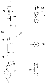
FIG. la is a front view of a duster of the present invention;
FIG. lb is a front view of a bristles and rod of the present
invention;
FIG. lc is a top view of a neck of the present invention;
FIG. 1d is a front view of a neck of the present invention;
FIG. 2a is a front view of a cleaning head of the present
invention;
FIG. 2b is a front view of a handle and rod of the present
invention;
FIG. 2c is a front view of a duster insert of the present
invention;
FIG. 3a is a top view of the handle with the insert removed;
7
CA 02647387 2008-12-04
WO 2007/106126 PCT/US2006/035089
FIG. 3b is a side view of the top portion of the handle;
FIG. 3c is a side view of the insert; and
FIG. 3d is the removable insert duster covering.
8
CA 02647387 2008-12-04
WO 2007/106126 PCT/US2006/035089
Detailed Description of Preferred Embodiment
FIG. 1 shows the cleaning device 10 of the present invention.
The cleaning device 10 can be any type of device for cleaning
and/or an applicator for uses such as sweeping, dusting, moping,
scrubbing and applying chemicals such as those for stripping,
waxing and cleaning. Cleaning apparatus 10 is preferably
fabricated of polymer materials, but can also include metals,
composites as well as cellulose and other natural materials.
The preferred embodiment of the present invention is a duster
10. The duster 10 includes cleaning head 21, elongated rod 100 and
handle 13.
As shown in Figs. 1b-1d, the cleaning head 21 includes a neck
20, bristles 101, rod 102, a.first locking mechanism 103, and a
second locking mechanism 105.
The neck 20 is removably connected to the elongated handle 100
at the distal end 19 of the handle 100. The connection is made by
female screw threads 30 located within the neck 20 of the head and
male threads 31 located on the distal end of the handle. To attach
the neck 20 to the handle 100 a user merely screws the handle 100
into the neck 20 and hand tightens the connection.
The head 21 also includes a rod 102 that holds the bristles
101 of the cleaning head 21. The bristles 101 of the cleaning head
are soft, long bristles. The bristles 101 are attached to a
material (not shown) for easier attachment. These bristles 101
mimic the old-time feather dusters of the past. The material of
9
CA 02647387 2008-12-04
WO 2007/106126 PCT/US2006/035089
the bristles 101 are attached to the rod 102 by the use of glue or
any other type of similar adhesive.
A substantial portion of the rod 102 accommodates the bristles
101 except for the distal end 103. The distal end 103 has a
cylindrical diameter that is slightly larger than the diameter of
the rod 102. This larger diameter is inserted into hole 105 for
locking the rod into the neck. This allows for easy replacement of
the cleaning*head 21.
The elongated rod 100 has a longitudinal axis X. The
elongated rod 100 is extendable/retractable and has an upper
portion 15 and a lower portion 17. The upper portion 15 has a
slightly larger cylindrical or tubular circumference than the lower
portion 17. This allows the lower portion 17 to retract into the
upper portion 16. At the point of intersection of the upper and
lower portion is a housing 16.
Rod 100 can be rigid or at least partially flexible and has a
varying length that is preferably the approximate length of a long
handled cleaning device such as a broom or a mop in which two hands
are used during cleaning.
In another embodiment rod 100 can have a fixed length. Rod
100 has an external perimeter that ergonomically accommodates the
use of cleaning device 10 with one or two hands.
The elongated rod 100 with telescoping feature has a stopper
18. This stopper 18 allows the lower portion 17 of the rod 100 to
retract only a certain distance within the upper portion 15. The
CA 02647387 2008-12-04
WO 2007/106126 PCT/US2006/035089
handle 13 may be either straight or ergonomically shaped to
accommodate a user's hand.
The rod 100 has a handle 13. The handle 13 includes a
gripping portion 14 attached to the upper portion 15 of the rod
100. The gripping portion 14 has attached at the top an insert
interface 13. The ir.sert interface is movable connected to the
gripping portion 14. That is, the insert interface rotates about
the longitudinal axis X. The insert interface 13 also contains a
through hole 62 as shown in Fig. 3b.
Insert interface 13 defines an opening 63 (as shown in Fig 3a)
aligned with longitudinal axis-X. Opening 63 is shaped and
dimensioned to receive insert 11 (See Fig. 3c) and extends a
predetermined length in.the distal direction within gripping
portion 14 and rod 1C0. The inner dimensions of the opening 63
contain a tubular wall that can advantageously accommodate any
insert 50 independent of the external shape of the handle 30. The
insert interface 13 also contains a first protuberance 60 and 61
both of which will be discussed more thoroughly below.
As shown in Fig. 3c, insert 11 includes handle 55, holding
means 50 and cleaning surface 43. The insert handle 55 preferably
has a length and shape for grasping with a single hand. Handle 55
securely interfaces with insert interface 13 to lock insert 11 in a
first position.
The handle 55 includes a through hole 12 to support the weight
of cleaning apparatus when suspended from a hook or bar positioned
11
CA 02647387 2008-12-04
WO 2007/106126 PCT/US2006/035089
through the through hole 12. The handle 55 includes an upper
portion 52 and a lower portion 53. The upper portion 52 is
constructed so that it interfaces with insert interface 13. The
lower portion 53 is placed within the insert interface 13.
At the bottom of the lower section 53 is a second protuberance
that surrounds the bottom portion of the handle 55. The second
protuberance 40 forms a cylindrical groove 41 that traverses the
circumference of the bottom of handle 55. This groove 41
interfaces with the protuberances 60 and 61 of the insert
interface. When the protuberances 60, 61 and the groove 41
interface, the insert 11 is locked into the insert interface 13.
To ensure a proper lock the insert interface 13 and insert handle
11 must be properly aligned. Also, when properly aligned through
holes 12 and 62 are aligned.
In use, the insert interface locks the insert 11 into the
handle 100. Insert 1.1 can be removed and replaced from within
handle 100. Duster 10 has a first position wherein insert 11 is
positioned in rod 100 and a second position wherein insert 11.is
removed from rod 100. Insert 11 in the second position can be used
independent of or in conjunction with duster 10.
Insert 11 has a distal end portion and a proximal end portion
that define a longitudinal axis-X', which is in coaxial alignment
with the handle 100. Distal end portion includes a cleaning head
43 and proximal end portion includes handle 55.
12
CA 02647387 2008-12-04
WO 2007/106126 PCT/US2006/035089
Insert 11 is a hand held device that includes a distal end
portion having a soft dust collecting type brush 43 shaped and
dimensioned for readily positioning into and removing from opening
63.
In this preferred embodiment, the distal end portion includes
dust-collecting fibers 43. Distal end portion is shown as
cylindrical in this one preferred embodiment, but it is understood
that distal end portion can have any cross-sectional shape normal
to longitudinal axis-X' that can be received in opening 63 and
include alternative dust collecting materials.
The dust collection fibers 43 are formed on a sleeve 43 as
shown in Fig 3d. This sleeve 43 is connected to the handle 55 via
predetermined form 50. In this embodiment, the predetermined form
50 is a metal wire but may be any type of device that will keep the
sleeve 43 erect when attached to the insert.
The metal wire 50 is attached to the lower portion 40 of the
handle. The metal wire 50 is shaped that wire 50 extends from the
lower portion 40 and loops around back to the lower portion 40
making an elongated loop 50. At the top portion of the elongated
loop 50 is a locking mechanism 45. To place the collection fibers
sleeve 43 on the insert 11 the collection fibers 43 slide along the
elongated loop 50 so that the elongated loop 50 extends along and
inside the full length of the collection fibers 43.
Once in place the collection fibers 43 have a string 44 and
holder 42 attached. The holder 42 is slide in between the
13
CA 02647387 2008-12-04
WO 2007/106126 PCT/US2006/035089
elongated loop 50 and the locking mechanism 45 is slide along the
loop 50 to hold the holder 42 firmly in place. This in turn locks
the collection device 43 firmly on the insert 11. Fig 2c shows the
sleeve 43 on the metal wire 50 with the locking mechanism 45 in
use.
The insert 11 in this preferred embodiment is preferably sized
for cleaning in small spaces such as between the slats of blinds,
for example. Insert 11 is removed and replaced within proximal end
portion by generally aligning longitudinal axis-X' with
longitudinal axis-X of handle 13.
While insert is shown to be aligned with longitudinal axis for
movement relative to longitudinal axis-X, insert 11 in the
embodiments of the present invention can be removed and replaced in
any manner to include axially, transverse to the longitudinal axis
and further include rotating about the longitudinal axis or pivotal
movements.
Cleaning apparatus 10 can also include a combination of
inserts 11 that define a kit. For example, cleaning device 10 can
also include one or more additional inserts 11 such as a flexible
whisk hand broom, a duster, a brush and/or scraper.
In operation, cleaning device 10 can be removed from a
preferred stored position wherein a hook, line or beam is
positioned through and/or into at least a portion of through holes
12 and 62 and the cleaning device is suspended from a wall, for
example. Cleaning apparatus 10 can be selectively employed using
14
CA 02647387 2008-12-04
WO 2007/106126 PCT/US2006/035089
head 20 of cleaning device 10 for cleaning, using insert 11
separately and/or in a third mode that can selectively combine the
use of both cleaning device 10 and insert 11.
Insert 11 is preferably moved from the first position to the
second position by moving insert 11 in the proximal direction along
longitudinal axis-X. Cleaning device 10 can include configurations
that support alternative movements between the first and second
positions such as transverse to the longitudinal axis and rotating
movements. Insert 11 can then be employed as a second cleaning
device. When the use of insert 11 is completed, insert 11 is moved
to the first position by any of the previously described methods.
Although the illustrative embodiments of the present
disclosure have been described with reference to the accompanying
drawings, it is to be understood that the disclosure is not limited
to those specific embodiments and that various other changes,
combinations and modifications will be apparent to one of ordinary
skill in the art without departing from the scope and spirit of the
invention which is to be determined with reference to the following
claims.