Note: Descriptions are shown in the official language in which they were submitted.
CA 02647447 2008-09-26
WO 2007/114460 PCT/JP2007/057516
1
Description
Tubular threaded joint
Technical Field
This invention relates to a tubular threaded joint suitable for use in
connecting
steel pipes such as oil country tubular goods (OCTG), riser pipes, and line
pipes.
More particularly, it relates to a tubular threaded joint which has excellent
resistance
to compression and which makes it easy to connect steel pipes in a vertical
state in
the field.
Background Art
Steel pipes such as OCTG (oil country tubular goods including oil well
tubing, casing, and drill pipes) used for the exploration and production of
oil wells
and gas wells, as well as riser pipes, line pipes, and the like are usually
connected by
a tubular threaded j oint.
A tubular threaded joint is constituted by a pin, which is a male threaded
element provided on an end portion of a first tubular member, and a box, which
is a
female threaded element provided on an end portion of a second tubular member.
Connection is carried out by engagement of the male screw thread and the
female
screw thread, which are both tapered screw threads. Typically, the first
tubular
member is a pipe such as an oil country tubular good, and the second tubular
member is a separate member in the form of a coupling (this type of tubular
threaded
joint is referred to as a coupling type). With this type, a pin is formed on
both ends
of the pipe, and a box is formed on both sides of the coupling.
There also exist integral-type tubular threaded joints which do not use a
coupling and in which a pin is formed on the outer surface of one end of a
pipe and a
box is formed on the inner surface of the other end of the pipe. With this
type, the
first tubular member is a first pipe and the second tubular member is a second
pipe.
In theory, a coupling-type tubular threaded joint in which a pin is formed on
a
coupling and a box is formed on a pipe is also possible. Below, an explanation
will
be given primarily of an exarnple of a tubular threaded joint of the type
first
3o described above in which a pin is formed on both ends of a pipe and a box
is formed
on a coupling.
CA 02647447 2008-09-26
WO 2007/114460 PCT/JP2007/057516
2
In the past, oil country tubular goods have been connected primarily using
standard threaded joints specified by API (American Petroleum Institute)
standards.
However, in recent years, as the environments for excavation and production of
crude oil and natural gas become severe, high-performance special threaded
joints
referred to as premium joints are being increasingly used.
In a premium joint, the pin and the box each have, in addition to a tapered
screw thread, a metal-to-metal seal surface, which makes direct metallic
contact in
the radial direction between mating members of the joint possible thereby
forming a
seal, and a torque shoulder surface which serves as an abutting stopper during
io tightening of the joint.
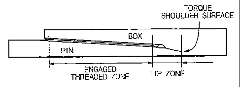
Figures 1(A) and 1(B) are schematic explanatory views of a typical premium
joint for oil country tubular goods of the coupling type. Figure 1(A) is an
overall
view, and Figure 1(B) is an enlarged view of a portion thereof. As shown in
Figure
1(B), this tubular threaded joint has a pin 1 which is a male threaded element
is provided on each end portion of a pipe and a box 2 which is a corresponding
female
threaded element provided on both sides of a coupling. On its outer surface,
the pin
1 has a tapered male threaded zone 11 and an unthreaded generally cylindrical
abutting portion 12 called a lip (referred to below as a lip zone) adjacent to
the male
threaded zone 11 on the side closer to the end. The lip zone 12 has a metal-to-
metal
20 seal surface 13 (also referred to below simply as a seal surface) on its
outer
peripheral surface and a torque shoulder surface 14 (also referred to below
simply as
a shoulder surface) on its end surface.
The corresponding box 2 has on its inner surface a tapered female threaded
zone 21, a metal-to-metal seal surface 23, and a shoulder surface 24 which can
25 interfit with, contact, or abut against the tapered male threaded zone 11,
the metal-to-
metal seal surface 13, and the shoulder surface 14, respectively, of the pin
1.
, Figure 2 is a schematic view for explaining the shape and dimensions of a
trapezoidal thread typified by a buttress thread specified by API. As in
Figures 1(A)
and 1(B), 11 is a male threaded zone and 21 is a female threaded zone. A screw
3o thread used in a premium joint is usually a trapezoidal screw thread
modeled on this
API buttress screw thread. Most premium joints employ the dimensions of an API
buttress screw thread with almost no changes with respect to the aspect ratio
(height-
to-width ratio), the flank angles (the angle of slope of the flanks), and the
like of
screw thread.
CA 02647447 2008-09-26
WO 2007/114460 PCT/JP2007/057516
3
By way of example, in the case of an API buttress screw thread having a
thread pitch of 5 TPI (5 threads per inch), the thread height 74, which is the
height to
the crest of a male thread, is 1.575 mm, the angle of slope 71 of the load
flank is 3 ,
the angle of slope 72 of the stabbing flank is 10 , and the clearance 73 in
the pipe
axial direction between the stabbing flanks of the male screw thread and the
female
screw thread when the load flanks contact each other (the stabbing flank
clearance)
is an average of approximately 100 m (30 - 180 m).
Concerning the shape of the threads of a tubular threaded joint, WO 92/15815
describes a tubular threaded joint in which the portion connecting the thread
crest
io and the stabbing flank of each thread of both a pin and a box is cut away
along a
straight line or a curve (namely, it is chamfered) such that it can function
as a contact
surface which is the first to contact when the pin is inserted into the box.
The
contact surfaces of the pin and the box are intended to contact each other to
facilitate
insertion when axial misalignment occurs during insertion of the pin into the
box.
U.S. Patent No. 6,322,110 discloses a tubular threaded joint based on the
same concept. Namely, a corner chamfer (chamfer of a corner portion) is
provided
on the stabbing flanks of the threads of both a pin and a box. When the pin is
inserted into the box, the corner chamfers engage with each other and
facilitate
insertion of the pin.
Above-described WO 92/15815 and US Patent No. 6,322,110 both facilitate
insertion of a pin by preventing misalignment of the insertion angle by
producing
contact between the pin and the box in the chamfered portions of the stabbing
flanks
and the crests. Accordingly, chamfered portions are necessary on both the pin
and
the box, and the intended effect is not exhibited if they are provided on just
one of
the two members. There is no description in these patent documents concerning
the
effect of chamfering on resistance to compression.
In a premium joint, a certain amount of interference in the radial direction
is
provided between the metal-to-metal seal surfaces of a pin and a box. When a
joint
is tightened until the shoulder surfaces of the pin and the box abut against
each
other, the seal surfaces of these members are in intimate contact around the
entire
circumference of the joint, thereby forming a seal.
The shoulder surfaces of the pin and the box function as stoppers which abut
at the time of tightening of the joint, and they also have the function of
bearing a
considerable proportion of the compressive load which acts on the joint.
CA 02647447 2008-09-26
WO 2007/114460 PCT/JP2007/057516
4
Accordingly, if the thickness of the shoulder surfaces is not large (or if the
stiffness
of the shoulder surfaces is not high), they cannot withstand a large
compressive load.
In the past, vertical wells were predominant, and threaded joints for oil
country tubular goods had sufficient performance if they could withstand the
tensile
load due to the weight of pipes connected thereto and could prevent leakage of
high
pressure fluid passing through their interior. However, in recent years, the
depth of
wells has been increasing, sloping wells and horizontal wells in which the
well bore
bends underground are increasing, and the development of wells in
disadvantageous
environments such as in the sea or in polar regions is increasing. As a
result, a
io greater variety of performance is being demanded of threaded joints, such
as
resistance to compression, resistance to bending, sealing ability against
external
pressure, and ease of use or pin insertion in the field.
When external pressure acts on the above-described conventional premium
joint, the applied external pressure is transmitted through gaps between the
screw
threads and penetrates to the portion just before the seal surfaces shown by
31 in
Figure 1(B). Since the lip zone has a much smaller wall thickness than the
body of
the pipes being connected, it sometimes undergoes deformation in the form of a
reduction in diameter due to the penetrated external pressure. If the external
pressure becomes high, a gap may develop between the seal surfaces, leading to
the
occurrence of leakage, e.g., a situation in which external fluid penetrates
into the
interior of the pipe body through the gap.
When a compressive load acts on a premium joint, for example, during
installation of an oil country tubular good in a horizontal well or a sloping
well,
since a premium joint usually has a relatively large gap between the stabbing
flanks
as is the case with the above-described API buttress screw thread, the ability
of the
screw threads of the joint to bear a compressive load is low, and most of the
compressive load is borne by the abutting shoulders thereof.
However, the wall thickness of the shoulder surfaces (the area for receiving
compressive loads which corresponds to the area of the lip end surface) is
normally
considerably smaller than that of the pipe body. Therefore, if a compressive
load
corresponding to 40 - 60% of the yield strength of the pipe body is applied,
with
most premium joints, the lip zone of the pin undergoes a substantial plastic
deformation, leading to a marked decrease in the sealing performance of the
seal
surface adjacent to this portion.
CA 02647447 2008-09-26
WO 2007/114460 PCT/JP2007/057516
The sealing ability of a joint against external pressure (external pressure
sealing ability) can be increased by increasing the stiffness of the pin so as
to
increase its resistance to deformation toward a reduction in diameter. For
this
purpose, a technique called swaging is often applied to the pipe towards the
axis in
5 order to increase the wall thickness of the lip zone.
However, if the amount of swaging is too great, with casing, there are cases
in
which a pipe which is inserted into its interior catches on the swaged
portion, and
with tubing, there are cases in which turbulence develops in a fluid such as
crude oil
flowing inside the tubing due to the swaged portion and causes erosion.
Therefore,
io the wall thickness of a lip zone can be increased by swaging only to a
limited extent.
WO 2004/109173 proposes a tubular threaded joint, as shown in Figure 3,
having a nose portion 15 provided between a metal-to-metal seal surface 13 and
a
torque shoulder surface 14 on the end surface of a pin 1. The generally
cylindrical
outer periphery of the nose portion 15 of the pin 1 does not contact the
opposing
portion of the box 2. On the other hand, the metal-to-metal seal portions 13
and 23
and the shoulder surfaces 14 and 24 of the pin and the box contact each other.
By
extending the lip zone of the pin so as to provide a noncontacting nose
portion 15 at
the end of the seal surface, the wall thickness of the lip zone including the
shoulder
surface and the seal surface can achieve a large value within a limited pipe
wall
thickness, and the resistance to compression and the sealing performance
against
external pressure of a tubular threaded joint can be markedly increased.
Disclosure of Invention
It is an object of the present invention to provide a tubular threaded joint
which has excellent resistance to compression and which facilitates connection
of
pipes in the field while in a vertical state.
Other objects, advantages, and features of the present invention will be
apparent from the following description.
In the tubular threaded joint proposed in above-described WO 2004/109173,
an improvement in resistance to compression is achieved by modifying the
portion
closer to the end of the pin than the metal-to-metal seal surface. Upon
repeated
investigations on the basis of that tubular threaded joint, the present
inventors found
that if the shape of a thread, and particularly the stabbing flank clearance,
which is
the clearance in the pipe axial direction between the stabbing flanks of the
male
CA 02647447 2008-09-26
WO 2007/114460 PCT/JP2007/057516
6
screw thread of the pin and the female screw thread of the box, and the length
of the
lip zone satisfy a certain relationship, plastic deformation of the lip zone
due to
compression is prevented from occurring, and the resistance to compression of
a
tubular threaded joint is further improved.
The present invention relates to a tubular threaded joint comprising a pin,
which is a male threaded element formed on an end portion of a first tubular
member, and a box, which is a female threaded element formed on an end portion
of
a second tubular member, wherein the pin and the box each have a threaded zone
having a screw thread and at least one torque shoulder surface, the male
thread in the
io threaded zone of the pin engages with the female thread in the threaded
zone of the
box, the at least one torque shoulder surface of the pin abuts against the at
least one
torque shoulder surface of the box in the axial direction of the tubular
joint, one of
the contacting torque shoulder surfaces is an end shoulder surface
constituting an
end surface in the transverse direction of the tubular member, and the threads
of the
male threaded zone and the female threaded zone are generally trapezoidal
threads
which have a (thread) crest, a load flank, and a stabbing flank and which have
a root
separating thread flanks.
A tubular threaded joint according to the present invention is characterized
in
that the lip length of the member having an end shoulder surface, which is the
axial
2o distance between the end shoulder surface and the load flank of the closest
engaged
thread to the end shoulder surface, is at least 140 times and preferably at
least 160
times the stabbing flank clearance, which is the axial clearance between the
stabbing
flank of male thread and the stabbing flank of female thread when the load
flank of
the male thread and the load flank of the female thread contact each other in
the
engaged male and female threads.
Some preferred embodiments of a tubular threaded joint according to the
present invention include the following:
- The stabbing flank clearance is at least 0.01 mm.
- The stabbing flank clearance is at most 0.3 mm.
- For the thread of at least one of the male and female threaded zones, the
stabbing flank comprises a first portion on the root side and a second portion
on the
crest side and the second portion has a larger average angle of slope with
respect to a
line perpendicular to the longitudinal axis of the joint than the first
portion.
- The first portion of the stabbing flank is a surface substantially limited
in
CA 02647447 2008-09-26
WO 2007/114460 PCT/JP2007/057516
7
longitudinal section by a straight line (like a generally conical surface),
and the
second portion thereof is a surface substantially limited in longitudinal
section by a
straight line, a bulging surface, or a concave surface.
- The angle of slope of the first portion with respect to a line perpendicular
to
the longitudinal axis of the joint is in the range of 5 - 25 .
- The average angle of slope of the second portion with respect to a line
perpendicular to the longitudinal axis of the joint is in the range of 20 - 70
.
- The thread of only one of the male and female threaded zones has a
stabbing flank having the first and second portions, and the angle of slope
with
io respect to a line perpendicular to the longitudinal axis of the first
portion of the
thread is the same as the angle of the stabbing flank of the thread of the
other
threaded zone.
- The product of the height in the radial direction of the first portion of
the
stabbing flank and the developed thread length of the engaged threads in the
threaded zones is larger than the difference between the nominal cross-
sectional area
of the bodies of the pipes being connected and the area of the abutting end
shoulder
surfaces of the joint.
- The crest and the root of each thread are parallel to the longitudinal axis
of
the tubular threaded joint (and hence to the pipe axis).
- The angle of slope of the load flanks of the engaged threads with respect to
a line perpendicular to the longitudinal axis of the joint is in the range of -
5 to +5 .
- For the thread of at least one of the male and female threaded zones, the
load flank of the thread comprises two portions in the form of a third portion
on the
root side and a fourth portion on the thread crest side, and the fourth
portion has a
larger average angle of slope with respect to a line perpendicular to the
longitudinal
axis of the joint than the third portion.
- The fourth portion has either a surface substantially limited in
longitudinal
section by a straight line or a bulging surface.
- Each of the pin and the box has a metal-to-metal seal surface between the
shoulder surface and the threaded zone.
- The metal-to-metal seal surface is provided in the vicinity of the threaded
zone.
- Each of the pin and the box has a noncontacting region in which the pin and
box do not contact each other between the metal-to-metal seal surface and the
CA 02647447 2008-09-26
WO 2007/114460 PCT/JP2007/057516
8
shoulder surface.
According to the present invention, by extending the length of the lip zone,
which is the distance in the member having a contacting end shoulder surface
of a
tubular threaded joint between the engaged threaded zone and the end shoulder
surface, to at least 140 times and preferably at least 160 times the stabbing
flank
clearance of the male and female threads, resistance to compression is
effectively
conferred by the stabbing flanks of the threads (or by the remaining effective
or
engaged portions of the stabbing flanks when the upper portion of the stabbing
flank
of the pin or the box has been removed by chamfering or beveling), and the
io resistance to compression of a tubular threaded joint is increased.
By controlling the stabbing flank clearance to be within a certain range,
variations in the tightening force at the time of tightening the threaded
joint can be
decreased. In addition, by suitably designing the shape of the threads and
particularly the direction of the crest and the root, the shape of a stabbing
flank, and
the shape of the chamfer on the stabbing flank side, problems and
misengagement of
threads due to deviation of the insertion angle at the time of restricted
tightening
operation such as tightening operation in the field in a vertical state which
is being
increasingly automated can be decreased, thereby making such a tightening
operation easy.
2o Brief Explanation of Drawings
Figures 1(A) is a schematic explanatory view of a typical conventional
tubular threaded joint of the coupling type referred to as a premium joint,
and Figure
1(B) is an enlarged view of a portion thereof.
Figure 2 is a schematic view for explaining the shape and dimensions of a
trapezoidal thread typified by an API buttress thread.
Figure 3 is a schematic explanatory view of a tubular threaded joint suitable
for application of the present invention in which a lip zone is extended and a
non-
contacting region is provided at the end of a metal-to-metal seal surface.
Figure 4 is an overall explanatory view showing each portion of a tubular
threaded joint.
Figure 5 is an explanatory view showing the longitudinal (axial) sectional
shape of the threaded zones of the pin and box of a tubular threaded joint.
Figure 6 is an explanatory view showing an embodiment in which the
CA 02647447 2008-09-26
WO 2007/114460 PCT/JP2007/057516
9
stabbing flank of a male thread of a pin have two portions with different
angles of
slope.
Figure 7 is an explanatory view showing a variation of the embodiment
shown in Figure 6.
Figure 8 is an explanatory view of an embodiment similar to Figure 6.
Figure 9 is an explanatory view of each portion of a stabbing flank and a load
flank of a pin (male) thread of an embodiment similar to Figure 6.
Figure 10 is a schematic longitudinal sectional view of an embodiment in
which a second shoulder surface is provided on the end surface of a box.
io Figure 11 is a schematic longitudinal sectional view of another embodiment
in which a second metal-to-metal seal surface is provided on the end portion
of a
box.
Figure 12 is a schematic view showing an embodiment in which a pin
member is given an increased wall thickness toward its end by swaging.
Figure 13 is a graph showing the results of an example.
Figure 14 is a graph showing the results of another example.
List of Reference Numerals:
1: pin, 2: box, 11: male threaded zone, 12: lip zone, 13: metal-to-metal seal
surface of pin, 14: end shoulder surface, 21: female threaded zone, 23: metal-
to-
metal seal surface of box, 24: shoulder surface of box, 71: load flank angle
of thread,
72: stabbing flank angle of thread, 73: stabbing flank clearance of thread.
Best Mode for Carrying Out the Invention
A tubular threaded joint according to the present invention can be applied to
either a coupling-type or an integral-type tubular threaded joint. In the case
of a
coupling type, typically a pin is formed on both ends of a pipe and a box is
formed
on both sides of a coupling, but it is possible to use the opposite
combination.
The basic concept of a tubular threaded joint according to the present
invention will be explained while referring to Figures 4 and 5. As shown by
the
schematic view in Figure 4, in a usual tubular threaded joint, a pin has a
threaded
zone having a male screw thread which engages with an opposing female screw
thread (an engaged thread zone in the figure), and a lip zone on the end side
thereof
which does not have engaged threads. The end surface in the transverse
direction at
the tip of the pin is an end shoulder surface functioning as a torque shoulder
surface.
CA 02647447 2008-09-26
WO 2007/114460 PCT/JP2007/057516
Correspondingly, a box has on its outer end a threaded zone having a female
screw
thread which engages with the opposing male screw thread and, on the inner
side
thereof, a generally cylindrical surface which does not have engaged threads.
The
surface in the transverse direction of the innermost portion of the box is a
torque
5 shoulder surface which abuts against the end shoulder surface of the pin.
As shown in the figure, the shoulder surfaces of the pin and the box which
abut against each other are in many cases an end shoulder surface of the pin
and a
corresponding innermost shoulder surface of the box. However, in the case of
an
integral-type joint, the surface area of the end surface of a pin having a
male screw
io thread formed on the outer surface of one end of a pipe is sometimes
smaller than the
surface area of the end surface of a box having a female screw thread formed
on the
other end of the pipe. In such a case, it is advantageous to use the end
surface of a
box as a torque shoulder surface since the resistance to compression can be
increased.
Thus, in the present invention, the lip zone means the portion of a threaded
joint member (a pin or a box) having an end shoulder surface (which functions
as a
torque shoulder surface at the time of tightening of the threaded joint) which
is
located closer to the end of the joint member than the engaged thread portion
thereof.
The screw threads of the threaded zones of the pin and the box engage with
each other. However, it is not necessary for the threads to engage along the
entire
length. As shown in Figure 1 (B), the end portions of the screw thread of one
or
both members and particularly the screw thread in the vicinity of the tip of
the box
need not be engaged with screw thread of the other meinber. In addition, as
shown
in Figure 3, an unengaged male thread can be added to a portion of the outer
surface
of the pin between the engaged threaded zone and the lip zone. By doing so,
the
stiffness of the pin against external pressure can be increased. In the
present
invention, the unengaged thread formed on the outer end (closer to the tip) of
the
threaded zone of a member (pin or box) having an end shoulder surface are
included
within the lip zone of the member.
Although it is not essential in the present invention, typically, a tubular
threaded joint has a metal-to-metal seal portion. For example, the outer
surface of
the lip zone of a pin and the unthreaded generally cylindrical inner surface
of a box
have a portion in which they contact each other to form metal-to-metal seal
surfaces
CA 02647447 2008-09-26
WO 2007/114460 PCT/JP2007/057516
11
13 and 23, as shown in Figure 3. From the standpoint of improving the
resistance to
compression of the lip zone, the metal-to-metal seal surfaces are preferably
provided
in a region of the lip zone which is close to the threaded zone, as
illustrated. Again
although not essential in the present invention, as shown in Figure 3, a
noncontacting region where the generally cylindrical surfaces of the pin and
box do
not contact each other is preferably provided in the lip zone at a location
between the
metal-to-metal seal surfaces 13, 23 and the shoulder surfaces 14, 24. As
described in
WO 2004/109173, the noncontacting region in the lip zone can further increase
the
resistance to compression of that portion. In addition, as shown in Figure 3,
the
io inner surfaces of the pin and the box on both sides of the shoulder
surfaces can be
removed to form chamfered portions 16 and 26. As a result, circularity of the
interior of the pipe around the abutting shoulder surfaces can be achieved so
that the
occurrence of turbulence of fluid flowing through the joint can be prevented.
Figure 5 schematically shows threads of a tubular threaded joint in
longitudinal section of the joint. For ease of explanation, all the corners of
the
threads shown therein are not chamfered at all. As already explained with
respect to
Figure 2, each of the engaged threads of the pin and the box has a crest, a
load flank
which is the thread flank on the rear side in the direction of insertion of
the pin, and
a stabbing flank which is the thread flank on the front side in the direction
of
insertion of the pin, and adjacent thread flanks are separated by a root. As
shown in
Figure 5, in a state in which the load flanks of the male screw thread of the
pin and
the female screw thread of the box contact (bear against) each other, the
clearance in
the longitudinal (axial) direction between the stabbing flanks of the male
screw
thread and the female screw thread is the (thread) stabbing flank clearance.
As
shown in the figure, there is also a clearance between the crest of the male
screw
thread and the root of the female screw thread. These clearances are necessary
so
that threaded engagement can be carried out without producing galling.
Figure 5 shows an example in which the stabbing flanks of the male screw
thread and the female screw thread are parallel so that the stabbing flank
clearance is
uniform over the entirety of the stabbing flanks of the engaged threads.
In the present invention; in a member (pin or box) which has an end shoulder
surface, the distance in the axial (longitudinal) direction of the member
between the
end shoulder surface and the load flank of the engaged thread located closest
to the
end shoulder surface (this distance substantially corresponds to the length of
the lip
CA 02647447 2008-09-26
WO 2007/114460 PCT/JP2007/057516
12
zone, so below it will be referred to as the lip length) is at least 140 times
and
preferably at least 160 times the stabbing flank clearance. As shown in Figure
3,
when the threaded zone (the threaded zone of the pin in the illustrated
example) has
unengaged threads on its end portion closest to the shoulder surface 14, the
axial
length of this unengaged thread portion, namely, the axial length of a
cylindrical
groove 32 provided on a box 2 in Figure 3, is included in the lip length.
As stated above, a member having an end shoulder surface which abuts
against an opposing innermost shoulder surface of the other member of a
tubular
threaded joint is typically a pin. In this case, the lip length of the pin
satisfies the
io above-described requirements with respect to the stabbing flank clearance.
However, as stated above, particularly with an integral-type tubular threaded
joint,
this end shoulder surface is sometimes provided on the box. In this case, the
lip
length of the box is made to satisfy the above-described requirement. When
both the
pin and box of a threaded joint have an end shoulder surface and hence a lip
zone, at
least one of the lip lengths of the pin and the box is made to satisfy the
requirement.
Under a compressive load, it is necessary in a tubular threaded joint that the
threads act in compression while the strain of the lip zone remains in the
elastic
region. If the lip length is at least 140 times and preferably at least 160
times the
stabbing flank clearance, even if a threaded joint undergoes compression in
the pipe
2o axial direction due to external pressure, the lip zone does not begin to
undergo
plastic deformation, and the stabbing flanks of the threads can contribute to
resistance to compression while the strain of the lip zone remains in the
state of
elastic deformation. As a result, the resistance to compression of a tubular
threaded
joint is markedly increased.
The stabbing flank clearance is preferably at least 0.01 mm (10 m) and at
most 0.3 mm (300 m). If the stabbing flank clearance is smaller than 0.01 mm,
the
clearance is so small that tightening of a threaded joint becomes unstable,
and it
becomes easy for galling to occur. On the other hand, if the stabbing flank
clearance
is larger than 0.3 mm, the clearance is so large as to allow external pressure
to easily
penetrate, thereby unduly increasing the external pressure to be applied to
the lip
zone during tightening. As shown in Figure 5, there is also a clearance in the
radial
direction of the joint between the crest of a male thread and the root of a
female
thread engaged therewith. There is no particular limitation on the dimension
of this
clearance in the radial direction, but normally it is designed so that a
sufficient
CA 02647447 2008-09-26
WO 2007/114460 PCT/JP2007/057516
13
clearance can be achieved taking into consideration the tolerances of the
thread
height.
For the thread of at least one of the pin and the box (preferably the male
thread of the pin, as shown in Figures 6 - 9), the stabbing flank of each
thread
comprises two portions in the form of a first portion on the root side and a
second
portion on the crest side. The second portion preferably has a larger average
angle
of slope with respect to a line perpendicular to the longitudinal axis than
the first
portion (namely, the second portion has a steeper slope than the first
portion). As a
result, as next explained, tightening of the threaded joint in the field can
be made
io easier while maintaining sufficient resistance to compression.
In general, the overall thread height in the engaged threaded zone of a
tubular
threaded joint (the height in the radial direction from the root to the crest
of a thread)
is designed so that the strength of the joint is at least the strength of the
pipe body
under a tensile load. Under a compressive load, the abutting shoulder surfaces
also
receive the applied load. Accordingly, the compressive load borne by the
threads is
reduced by the amount received by the cross-sectional area of the abutting
shoulder
surfaces. Namely, the thread height necessary for supporting a load is smaller
under
a compressive load than under a tensile load. A tensile load is borne by the
load
flanks of the engaged threads of a joint in the state shown in Figure 5 in
which the
load flanks contact each other, while a compressive load is borne by the
stabbing
flanks of the engaged threads in an unshown state in which the stabbing flanks
contact each other. Therefore, the thread height on the stabbing flank side of
the
threads includes a margin.
In a tubular threaded joint having abutting shoulder surfaces and engaged
threads which both contribute to resistance to compression or receive a
compressive
laod, the compression rate of the joint can be expressed by the ratio of the
total
cross-sectional area in the transverse or radial direction of the compression-
receiving
surfaces of the joint to the radial cross-sectional area of the pipe body,
which is
given by the following equation.
Compression rate (%) ={ [(cumulative projected cross-sectional area of
engaged threads) + (cross-sectional area of abutting shoulder surfaces)] /
(cross-
sectional area of pipe body)} X 100.
CA 02647447 2008-09-26
WO 2007/114460 PCT/JP2007/057516
14
The cross-sectional area of abutting shoulder surfaces is typically about 40 -
50 % of that of pipe body. Therefore, even with a compression rate of 100% in
which a compressive load corresponding to the yield strength of the pipe body
is
applied to a tubular threaded joint, the joint can withstand the compressive
load if
the thread height of the stabbing flanks is at least 50 - 60% of the overall
thread
height. Accordingly, if the first portion on the root side of the stabbing
flanks has at
least the height necessary to support a compressive load (such as 50 - 60% of
the
overall thread height), the remaining second portion on the crest side of the
stabbing
flanks may have a larger angle of slope, which makes the portion unable to
receive a
io compressive load, and even in this case, a sufficient resistance to
compression can be
achieved.
Concerning the resistance to compression of a tubular threaded joint, from in
the past, plastic deformation of the end shoulder surface disposed at the end
of the
lip zone was thought to be a major cause of a loss of resistance to
compression, so
the ratio of the cross-sectional area of the shoulder area to the cross-
sectional area of
the pipe body is an important factor. In the present invention, initial
contact of the
thread stabbing flanks takes place when deformation of the lip zone remains in
the
elastic region, so resistance to compression of a tubular threaded joint is
controlled
by the sum of the cross-sectional area of the abutting shoulder portions and
the
cumulative projected cross-sectional area of the engaged (effective) thread
stabbing
flanks, which correspond to the above-described first portion of the stabbing
flank.
The height of the first portion which contributes to compression rate in the
thread
stabbing flanks can be determined in this manner.
The height in the radial direction of the first portion of the chamfered
stabbing flank of the male thread of the pin, for example, is preferably set
such that
the product of the height in the radial direction of this first portion and
the developed
thread length of the engaged threads (pin and box screw threads engaged with
each
other) is larger than the difference between the nominal radial cross-
sectional area of
the body of the pipes being connected and the radial cross-sectional area of
the
3o abutting shoulder surfaces of the joint. By doing so, the joint can have
resistance to
compression which can withstand a compressive load corresponding to the above-
mentioned 100% compression rate. The cross-sectional area of the pipe body of
course means the cross-sectional area in the radial direction of the wall of
the pipe.
When a threaded joint has abutting shoulder surfaces in two or more locations,
the
CA 02647447 2008-09-26
WO 2007/114460 PCT/JP2007/057516
cross-sectional area of the abutting shoulder surfaces is the sum of the cross-
sectional areas at the two or more locations.
By giving the second portion of the stabbing flank a chamfered shape which
is optimal from the standpoint of tightening operation in the field, it is
possible to
5 realize an easy tightening operation in the field while maintaining
excellent
resistance to compression achieved by the first portion.
The first portion of the stabbing flank of the screw thread of a member (e.g.,
a pin) should be parallel to the stabbing flank of the screw thread of the
other
member so as to make a uniform stabbing flank clearance in the first portion
and
io allow the first portion of the stabbing flank to uniformly contact the
stabbing flank
of the other screw thread at the time of tightening the joint. Accordingly,
the first
portion of the stabbing flank of the screw thread and the stabbing flank of
the other
screw thread are preferably generally conical surfaces.
Here, a generally conical surface means a surface substantially limited in
15 longitudinal section (along the pipe axis) by a straight line. More
specifically, it
means that at least 50% and preferably at least 80% of the height is conical
or is
limited in longitudinal section by a straight line. Thus, a generally conical
surface
includes the case in which the upper end and/or the lower end is slightly
rounded.
The second portion of a stabbing flank having a larger angle of slope is a
chamfered portion. This chamfering makes it easy to insert a pin into a box at
the
time of tightening in the field. As shown in Figure 6, a chamfer of the second
portion may be a chamfer such that the cross section in the pipe axial
direction is
linear (a chamfer with a generally conical surface), or as shown in Figure 7,
it may
be a chamfer such that the axial cross section is arcuate (a convex bulging
surface or
a concave surface). Figure 7 shows an example of a bulging surface. It is also
possible for a chamfer to combine these shapes.
When the first portion of a stabbing flank has a generally conical shape, the
angle of slope of the surface with respect to a line perpendicular to the pipe
axis (the
longitudinal axis of the pipe and joint) is preferably in the range of 5 - 25
.
3o Regardless of the chamfered shape of the second portion which is a
chamfered
portion, the average angle of slope of the second portion with respect to a
line
perpendicular to the pipe axis is preferably in the range of 20 - 70 , as
shown in
Figure 8.
In the tubular threaded joints described in above-mentioned WO 92/15815
CA 02647447 2008-09-26
WO 2007/114460 PCT/JP2007/057516
16
and US Patent No. 6,322,110, not only is the stabbing flank of a male thread
chamfered in the vicinity of the crest, but a corresponding shape is imparted
to the
opposing portion of a female screw thread. Accordingly, each female screw
thread
also has two portions with different angles of slope. In the present
invention, as
shown in Figures 6 - 8, it is not necessary to impart a shape corresponding to
the
chamfer of the male screw thread to the stabbing flank of the female screw
thread.
The crests and roots of the screw threads are preferably parallel to the pipe
axial direction for all the male and female threads. Namely, although the
threaded
zones of the pin and the box of a tubular threaded joint are in the form of
tapered
io screw threads, it is preferable that the crest and root of each thread not
be parallel to
the tapered slope but be parallel to the pipe axis. In this manner, problems
due to
deviation of the insertion angle of a pin at the time of tightening operation
in the
field are reduced.
The angle with respect to a line perpendicular to the pipe axis of the load
flanks of the threads of the pin and the box is preferably in the range of -5
to +50.
Here, when the angle of slope of a load flank is negative, it means, as shown
in
Figures 5 - 9, for example, that the load flank is leaning leftwards in the
figures with
respect to a line perpendicular to the pipe axis.
The load flank of the thread of at least one of the pin and the box and
preferably of the male thread of the pin may also comprise two portions in the
form
of a third portion on the root side and a fourth portion on the crest side, as
shown in
Figures 6 - 9 and particularly in Figure 9. The fourth portion should have a
larger
average angle of slope (on the plus side) with respect to a line perpendicular
to the
pipe axis than the third portion. In this case, the third portion of the load
flank is
preferably a generally conical surface, and its angle of slope is preferably
in the
range of -5 to +5 . The fourth portion may be a generally conical surface as
shown
in the figure, or it may be a bulging surface.
The fourth portion of a load flank is also a kind of chamfer which makes it
easy to insert a pin into a box at the time of tightening in the field. A
tensile load is
3o borne only by the load flanks, and there is no contribution by the shoulder
surfaces
to resisting tensile force. Therefore, it is necessary to make the area of the
contact
portions of the male thread and the female thread larger for the load flanks
(the third
portion thereof) than for the stabbing flanks (the first portion thereof).
Thus, it is
preferred that the fourth portion of a load flank have a smaller height than
the second
CA 02647447 2008-09-26
WO 2007/114460 PCT/JP2007/057516
17
portion of a stabbing flank so that an adequate area for contact is left in
the third
portion of the load flank which contributes to tensile performance. For this
reason,
the height of the fourth portion is preferably at most 20% of the thread
height.
Both the pin and the box preferably have a metal-to-metal seal surface
between the shoulder surface and the engaged thread portion, i.e., in the lip
zone. In
the present invention, the lip length is at least 140 times the stabbing flank
clearance
of the thread, which is considerably longer compared to a conventional one. In
this
case, if the metal-to-metal seal surface is provided over the entire length of
the lip
zone, it becomes easy for galling to occur during tightening operation.
Therefore,
io the metal-to-metal seal surface is provided over a portion of the lip zone
and
preferably in a region thereof close to the threaded zone. The length of the
metal-to-
metal seal portion is preferably at most 25% of the lip length.
The pin and the box each preferably have a noncontacting region (where they
do not contact each other) between the metal-to-metal seal surface and the
shoulder
surface. By providing such a noncontacting region between the metal-to-metal
seal
surface and the shoulder surface, the length of the lip zone can be increased,
and at
the time of application of a compressive load, it becomes possible for the
compressive load to be supported by the contacting stabbing flanks of the
threaded
zones of the pin and the box and the abutting shoulder surfaces while the
strain of
the lip zone remains in the elastic region, and the lip zone including the
metal-to-
metal seal surface takes on a design which is resistant to plastic deformation
due to
compression.
This noncontacting region may'be a portion in which either the pin or the box
does not have threads as shown in Figure 3, or it may be an unengaged thread
portion in which only one member of the pin and box has threads, or it may
include
both portions. The length of this noncontacting region is preferably at least
15% of
the lip length. The length of a portion of a noncontacting region which does
not
have threads in either member is preferably at most 33% of the lip length.
Other than the above-described relationship between the stabbing flank
clearance and the lip length and the preferred shape of the stabbing flank and
the
load flank of the engaged thread of at least one member and preferably of the
pin,
there are no particular restrictions on the shape or structure of a tubular
threaded
joint. For example, an end shoulder surface and a metal-to-metal seal surface
are not
limited to one location, and as shown in Figure 10, a second end shoulder
surface 33
CA 02647447 2008-09-26
WO 2007/114460 PCT/JP2007/057516
18
can be provided at the tip end of the box 2, or as shown in Figure 11, a
second
metal-to-metal seal surfaces 34 can be provided on both members near the tip
end of
the box 2. In addition, as shown in Figure 12, the thicknesses of a pipe
and/or a
coupling can be increased in the vicinity of the joint portion by swaging or
overlaying.
In particular, as shown in Figure 10, when a lip zone having an end shoulder
surface is provided at the tip end of each of the box and the pin, or in other
words,
when a tubular threaded joint has two lip zones each having an end shoulder
surface
which functions as a torque shoulder surface at the time of tightening of the
joint, the
io relationship between the lip length and the stabbing flank clearance
specified by the
present invention should be satisfied for at least one lip zone.
The following examples are presented to further illustrate the present
invention. These examples are to be considered in all respects as illustrative
and not
restrictive.
Example 1
In order to clearly demonstrate the effects of the present invention, a
compressive load was applied to the test members shown in Table 1 by
tightening,
and deformation of the lip zone was observed.
Each of the test members shown in Table 1 was a threaded joint for oil
country tubular goods of the coupling type like that shown in Figure 3. They
were
for use with respect to a 9.625" x 53.5 (lb/ft) steel pipe (outer diameter of
244.5 mm
and wall thickness of 13.84 mm). The steel used for all of the test members
was that
specified by API specification P 110. The shoulder surfaces were an end
shoulder
surface located at the end of the pin and a corresponding shoulder surface of
the box.
The lip zone had on its outer periphery a metal-to-metal seal surface (length
of 5.5
mm) in the vicinity of the threaded zone and a noncontacting region on the
outer end
side thereof. In contrast to Figure 3, there was no unengaged thread on the
end
portion of the threaded zone.
The screw thread shape was the same for all the test members, with a taper of
1/18, a male thread height 74 of 1.3 mm, a thread pitch of 5.08 mm, a stabbing
flank
angle 72 of 10 , and a load flank angle 71 of -3 . A chamfer of the stabbing
flanks
and the load flanks for both the male screw thread and the female screw thread
was
only a minimal rounding as shown in Figure 2, and the stabbing flanks
consisted
CA 02647447 2008-09-26
WO 2007/114460 PCT/JP2007/057516
19
essentially of only one portion. The stabbing flank clearance 73 and the
length of
the lip zone of the joint were varied as shown in Table 1.
For each of the test members, tightening of the joint was terminated
immediately after the shoulder surfaces of the pin and the box abutted against
each
other. The results are shown in Table 1 and Figure 13.
Table 1
Stabbing Level of compressive load applied
Lip(Ae) gth flank A/B (% with respect to yield strength of pipe body)*
clearance
(nm1) (B) (mn1) 40% 50% 60% 70% 80% 90% 100%
15 0.10 150 0 0 0 0 0 0 0
0.15 100 0 0 0 X X X X
15 0.20 75 0 X X X X X X
0.10 200 0 0 0 0 0 0 0
20 0.15 133 0 0 0 0 0 0 X
15 20 0.20 100 0 0 0 X X X X
0.10 250 0 0 0 0 0 0 0
25 0.15 167 0 0 0 0 0 0 0
X X
25 0.20 125 0 0 0 0 J-o-
*0: no plastic deformation of lip after application of compressive load;
20 X: plastic deformation occurred.
As can be seen from the results in Table 1 and Figure 13, if the requirement
of the present invention that the lip length be at least 140 times the
stabbing flank
clearance is satisfied, even when a compressive force corresponding to 100% of
the
yield strength of the pipe body is applied, plastic deformation of the lip
zone does
25 not occur and only elastic deformation takes place, so the resistance to
compression
is excellent.
Example 2
An evaluation test was carried out in the same manner as in Example 1, but in
this example, the stabbing flank of the male thread of the pin was divided
into a first
portion on the root side and a second portion on the crest side having
different slope
CA 02647447 2008-09-26
WO 2007/114460 PCT/JP2007/057516
angles. In this example, in order to simplify analysis, as shown in Figures 6
and 8,
the first portion and the second portion of the stabbing flanks were both made
conical surfaces (namely, having a longitudinal section along the pipe axis
substantially formed by a straight line). The angle of slope of the stabbing
flank was
5 10 for the first portion and 45 for the second portion. The ratio of the
lip length to
the stabbing flank clearance was 200 (the stabbing flank clearance was 0.1 mm
and
the lip length was 20 mm). By varying the height of the first portion of the
stabbing
flank, the ratio of the height of the first portion with respect to the
overall thread
height (the thread stabbing flank height ratio in Table 2) was varied as shown
in
io Table 2. In addition, by varying the diameter of the end portion of the lip
zone, i.e.,
the area of the end shoulder surface of the pin, the ratio of the cross-
sectional area of
the abutting shoulder surfaces and that of the cumulative cross-sectional area
of
engaged (effective) stabbing flanks (= the product of the thread height of the
first
portion of the stabbing flank of the male thread and the developed thread
length of
15 the engaged thread) with respect to the cross-sectional area of the pipe
body was
varied as shown in the column of cross-sectional area ratio in Table 2. In
this table,
for conditions 7, 8, and 9, the pin end was subjected to swaging so as to have
an
increased wall thickness and hence an increased cross-sectional area of the
end
shoulder portion at its end.
20 Analysis was carried out by evaluating the condition of the lip zone
(whether
there was deformation or breakage) after a compressive load corresponding to
100%
of the yield strength of the pipe body (namely, an elastic compression rate
calculated
by the above-described formula) and an external pressure specified by API were
applied. The results are shown in Table 2 and Figure 14. In Table 2, the cross-
sectional area of the abutting shoulder surfaces and the cumulative cross-
sectional
area of engaged stabbing flanks are shown as the ratio (%) with respect to the
nominal cross-sectional area of the bodies of the pipes being connected by the
threaded joint, which is taken as 100%.
CA 02647447 2008-09-26
WO 2007/114460 PCT/JP2007/057516
21
o a) o o (D a) o
0 0 0
F '~ o o'~ o 0
4-
N ~N N N N N N N
=~~ U~
M M M M M M M M M
kn Vn V7 k('1 V) kn k/'1 V7 in
n
b U
p t
~
41
p y
~p^
,~ ,,,.y ~y ~ o 0 0 0 0 0 0 0 0
N cn ~.~ T3 O O O O O O O O O
~~~ O O O O O O O O O
N
bA
~ ~~~~ ~^- o 0 0 0 0 0 0 0 0
~ .L1~ \ \ \ \ \ \ \ \ \
0 ~~ ~ ~ M l~ V~ M l- V 1 M
~.~.s
p o 0 0 0 0 0 0 0 0
..~ ~ "~ \ \ \ \ \ \
oC:)o doo "0 C:) 00 "o CD 00
U cd
cs
0
o
~. bo
0 0 0 0 0 0 0 0 0
~ \ \ \ \ \ \ \ \ \
~~ ~ o 0 0 0~ o~o 0 0 0
U
= U
O
=
.-~ N M d V') ~o [~ 00 C\
U
CA 02647447 2008-09-26
WO 2007/114460 PCT/JP2007/057516
22
As can be seen from Table 2 and Figure 14, when the cumulative cross-
sectional area of engaged stabbing flanks of the threads was larger than the
difference between the nominal cross-sectional area of the pipe body (100%)
and the
cross-sectional area of the end shoulder surface, i.e., when the following
relationship
was satisfied, the resistance to compression of the threaded joint exceeded
the
resistance to compression of the pipe bodies, and as a result, the lip zone
did not
deform.
[Cumulative cross-sectional area of engaged stabbing flanks] > [nominal
cross-sectional area of pipe body] - [cross-sectional area of abutting
shoulder
surfaces]
Although the present invention has been explained with respect to preferred
embodiments, these embodiments are merely examples and do not restrict the
present
invention. It is clear to those skilled in the art that the above elnbodiments
can be
modified in various ways without departing from the scope of the present
invention
as described by the claims.