Note: Descriptions are shown in the official language in which they were submitted.
CA 02647486 2008-12-19
THREE-DIMENSIONAL IMAGE RECONSTRUCTION USING DOPPLER
ULTRASOUND
FIELD OF THE INVENTION
The present invention relates generally to imaging,
and in particular to medical imaging.
BACKGROUND OF THE INVENTION
Methods for 3-D mapping of the endocardium (i.e.,
the inner surfaces of the heart) are known in the art.
For example, U.S. Patent 5,738,096 to Ben-Haim, which is
assigned to the assignee of the present invention, and
whose disclosure is incorporated herein by reference,
describes a method for constructing a map of the heart.
An invasive probe or catheter is brought into contact
with multiple locations on the wall of the heart. The
position of the invasive probe is determined for each
location, and the positions are combined to form a
structural map of at least a portion of the heart.
In some systems, such as the one described by U.S.
Patent 5,738,096 cited above, additional physiological
properties, as well as local electrical activity on the
surface of the heart, are also acquired by the catheter.
A corresponding map incorporates the acquired local
information.
Some systems use hybrid catheters that incorporate
position sensing. For example, U.S. Patent 6,690,963 to
Ben-Haim et al., which is assigned to the assignee of the
present invention, and whose disclosure is incorporated
herein by reference, describes a locating system for
1
CA 02647486 2008-12-19
determining the location and orientation of an invasive
medical instrument.
U.S. Patent Application Publication No. 2006/0241445
by Altmann et al., which is assigned to the assignee of
the present invention, and whose disclosure is
incorporated herein by reference, describes a method for
modeling an anatomical structure. A plurality of
ultrasonic images of the anatomical structure is acquired
using an ultrasonic sensor at different spatial
positions. Location and orientation coordinates of the
ultrasonic sensor are measured at each of these spatial
positions. Contours-of-interest that refer to features of
the anatomical structure are marked in one or more of the
ultrasonic images. A three-dimensional (3-D) model of the
anatomical structure is constructed, based on the
contours-of-interest and on the measured location and
orientation coordinates.
U.S. Patent 6,773,402 to Govari et al., which is
assigned to the assignee of the present invention, and
whose disclosure is incorporated herein by reference,
describes a system for 3-D mapping and geometrical
reconstruction of body cavities, particularly of the
heart. The system uses a cardiac catheter comprising a
plurality of acoustic transducers, which emit ultrasound
waves that are reflected from the surface of the cavity
and are received by the transducers. The distance from
each of the transducers to a point or area on the surface
opposite the transducer is determined, and the distance
measurements are combined to reconstruct the 3-D shape of
the surface. The catheter also comprises position
2
CA 02647486 2008-12-19
sensors, which are used to determine location and
orientation coordinates of the catheter within the heart.
In one embodiment, the processing circuitry analyzes the
frequency, as well as the time of flight, of the
reflected waves in order to detect a Doppler shift. The
Doppler measurement is used to determine and map the
heart wall velocity.
U.S Patent 5,961,460, to Guracar et al., whose
disclosure is incorporated herein by reference, describes
an ultrasonic imaging system that generates Doppler and
B-mode (two-dimensional diagnostic ultrasound) image
signals, and then uses a modulated, non-linear mapping
function to combine the Doppler and B-mode image signals
into an output signal.
U.S. Patent 6,679,843, to Ma et al., whose
disclosure is incorporated herein by reference, describes
a method of reducing an elevation fold-in artifact by
combining Doppler and B-mode image signals using a
modulated, non-linear function. Portions of the B-mode
image signal associated with stationary tissue are intact
while portions of the B-mode image signal associated with
flow are substantially suppressed.
3
CA 02647486 2008-12-19
SZTMMARY OF THE INVENTION
Three-dimensional (3-D) images of organs such as the
heart are useful in many catheter-based diagnostic and
therapeutic applications. Real-time imaging improves
physician performance and enables even relatively
inexperienced physicians to perform complex surgical
procedures more easily. 3-D imaging also helps to reduce
the time needed to perform some surgical procedures.
Additionally, 3-D ultrasonic images may be used in
planning complex procedures and catheter maneuvers.
To create a meaningful 3-D reconstruction from two-
dimensional (2-D) ultrasound scans, the computer must
know which features of the 2-D images represent actual
contours of the organ of interest. A common solution to
this problem in the prior art is for a user of the
ultrasound imaging system to "help" the computer by
tracing the contours on the 2-D image. This solution is
used, for example, in U.S. Patent Application Publication
No. 2006/0241445 cited above.
Some embodiments of the present invention use
Doppler ultrasound to provide contour locations of the
organ automatically or semi-automatically, wherein the
user needs at most to review and possibly correct
contours generated by the computer. In the case of the
heart, for example, Doppler images clearly differentiate
the interior volume of the heart from the heart walls due
to the speed of blood flow within the heart. This
phenomenon is particularly marked in the blood vessels
leading into and out of the heart chambers.
4
CA 02647486 2008-12-19
Alternate embodiments of the present invention use
Doppler ultrasound to determine locations of movement,
typically of blood, but also of tissue. These locations
may be used to reconstruct a 3-D model of regions of
movement, such as blood flow and/or a surface bounding
such regions, without forming or displaying contours of
organs surrounding the regions.
There is therefore provided, according to an
embodiment of the present invention a method for imaging
an anatomical structure, including:
acquiring a plurality of ultrasonic images of the
anatomical structure, at least one of the images
comprising Doppler information;
generating one or more contours of the anatomical
structure using the Doppler information; and
reconstructing a three-dimensional image of the
anatomical structure from the plurality of ultrasonic
images using the one or more contours.
Typically, generating the one or more contours
includes determining a boundary between a first region of
the anatomical structure having a speed of movement
greater than or equal to a first value and a second
region of the anatomical structure wherein the speed of
movement is less than or equal to a second value smaller
than the first value. The first value may be 0.08 m/s and
the second value may be 0.03 m/s.
In one embodiment the anatomical structure includes
a heart, and acquiring the plurality of ultrasonic images
5
CA 02647486 2008-12-19
includes inserting a catheter including an ultrasonic
sensor into a chamber of the heart and moving the
catheter between a plurality of spatial positions within
the chamber. The catheter may be provided already
positioned at the chamber of the heart, and may be
movable between a plurality of spatial positions within
the chamber. Typically, the method also includes
measuring location and orientation coordinates of the
ultrasonic sensor, and synchronizing the plurality of
ultrasonic images and the location and orientation
coordinates relative to a synchronizing signal including
one of an electrocardiogram (ECG) signal, an internally-
generated synchronization signal and an externally-
supplied synchronization signal.
The three-dimensional image may include a three-
dimensional surface model of the anatomical structure,
and the method may further include:
measuring at least one of a tissue characteristic, a
temperature and a rate of flow of blood, synchronized to
the synchronizing signal, to produce a parametric map;
and
overlaying the parametric map on the three-
dimensional surface model.
In a disclosed embodiment acquiring the plurality of
ultrasonic images includes moving an ultrasonic sensor
generating the ultrasonic images so that a velocity of
movement of the ultrasonic sensor is less than a pre-
determined threshold velocity.
6
CA 02647486 2008-12-19
Alternatively or additionally, acquiring the
plurality of ultrasonic images includes determining a
velocity of movement of an ultrasonic sensor generating
the ultrasonic images, and correcting the Doppler
information responsively to the velocity of movement.
The three-dimensional image may include a three-
dimensional skeleton model of the anatomical structure
and/or a three-dimensional surface model of the
anatomical structure.
The method may include overlaying an electro-
anatomical map on the three-dimensional surface model.
The method may include overlaying information
imported from one or more of a Magnetic Resonance Imaging
(MRI) system, a Computerized Tomography (CT) system and
an x-ray imaging system on the three-dimensional surface
model.
There is further provided, according to an
embodiment of the present invention, a method for imaging
an anatomical structure, including:
acquiring a plurality of two-dimensional Doppler
images of elements moving in proximity to the anatomical
structure; and
reconstructing a three-dimensional image of the
moving elements.
Typically, reconstructing the three-dimensional
image includes displaying the three-dimensional image
absent the anatomical structure.
7
CA 02647486 2008-12-19
In one embodiment the method includes setting a
threshold speed for the moving elements, and
reconstructing the three-dimensional image includes
displaying the moving elements having speeds greater than
the threshold speed.
In a disclosed embodiment reconstructing the three-
dimensional image includes determining a surface bounding
at least some of the elements, and displaying the
surface.
There is further provided, according to an
embodiment of the present invention, a system for imaging
an anatomical structure, including:
a probe, including an ultrasonic sensor, which is
configured to acquire a plurality of ultrasonic images of
the anatomical structure, at least one of the images
including Doppler information; and
a processor, coupled to the ultrasonic sensor, which
is configured to generate one or more contours of the
anatomical structure using the Doppler information and to
reconstruct a three-dimensional image of the anatomical
structure from the plurality of ultrasonic images using
the one or more contours.
There is further provided, according to an
embodiment of the present invention, a system for imaging
an anatomical structure, including:
a probe, including an ultrasonic sensor, which is
configured to acquire a plurality of two-dimensional
8
CA 02647486 2008-12-19
Doppler images of elements moving in proximity to the
anatomical structure; and
a processor which is configured to reconstruct a
three-dimensional image of the moving elements from the
two-dimensional Doppler images.
There is further provided, according to an
embodiment of the present invention a computer software
product for imaging an anatomical structure, including a
computer-readable medium in which computer program
instructions are stored, which instructions, when read by
a computer, cause the computer to acquire a plurality of
ultrasonic images of the anatomical structure, at least
one of the images including Doppler information, to
generate one or more contours of the anatomical structure
using the Doppler information, and to reconstruct a
three-dimensional image of the anatomical structure from
the plurality of ultrasonic images using the one or more
contours.
BRIEF DESCRIPTION OF THE DRAWINGS
For a better understanding of the present invention,
reference is made to the detailed description of the
invention, by way of example, which is to be read in
conjunction with the following drawings, wherein like
elements are given like reference numerals, and wherein:
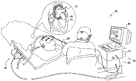
Fig. 1 is a schematic, pictorial illustration of a
system for cardiac mapping and imaging, in accordance
with an embodiment of the present invention;
9
CA 02647486 2008-12-19
Fig. 2 is a schematic, pictorial illustration of a
catheter, in accordance with an embodiment of the present
invention;
Figs. 3-6 are schematic images of a non-human heart,
in accordance with an embodiment of the present
invention;
Fig. 7 is a 3-D skeleton model of the heart shown in
Figs. 3-6, in accordance with an embodiment of the
present invention;
Fig. 8 is a 3-D surface model of the heart shown in
Figs. 3-6, in accordance with an embodiment of the
present invention;
Fig. 9 is a flow chart that schematically
illustrates a method for cardiac mapping and imaging, in
accordance with an embodiment of the present invention;
Fig. 10 is a schematic image of a non-human heart,
in accordance with an alternate embodiment of the present
invention; and
Fig. 11 is a flow chart that schematically
illustrates a method for cardiac mapping and imaging, in
accordance with an alternate embodiment of the present
invention.
CA 02647486 2008-12-19
DETAILED DESCRIPTION OF THE INVENTION
In the following description, numerous specific
details are set forth in order to provide a thorough
understanding of the present invention. It will be
apparent to one skilled in the art, however, that the
present invention may be practiced without these specific
details. In other instances, well-known circuits, control
logic, and the details of computer program instructions
for conventional algorithms and processes have not been
shown in detail in order not to obscure the present
invention unnecessarily.
Turning now to the drawings, reference is initially
made to Fig. 1, which is a schematic, pictorial
illustration of a system 20 for mapping and imaging a
heart 24 of a patient, in accordance with an embodiment
of the present invention. System 20 comprises a probe,
for example a catheter 27, which is inserted by a
physician into a chamber of the heart through a vein or
artery. Catheter 27 typically comprises a handle 28 for
operation of the catheter by the physician. Suitable
controls on handle 28 enable the physician to steer,
locate and orient a distal end 29 of catheter 27 as
desired.
System 20 comprises a positioning subsystem 30 that
measures location and orientation coordinates of distal
end 29 of catheter 27. In the specification and in the
claims, the term "location" refers to the spatial
coordinates of an object such as the distal end of the
catheter, the term "orientation" refers to angular
11
CA 02647486 2008-12-19
coordinates of the object, and the term "position" refers
to the full positional information of the object,
comprising both location and orientation coordinates.
In one embodiment, positioning subsystem 30
comprises a magnetic position tracking system that
determines the position of distal end 29 of catheter 27.
Positioning subsystem 30 generates magnetic fields in a
predefined working volume in the vicinity of a patient,
and senses these fields in a sensor, described below, in
catheter 27. Positioning subsystem 30 typically comprises
a set of external radiators, such as field generating
coils 31, which are located in fixed, known positions
external to the patient. Coils 31 generate fields,
typically magnetic fields, in the vicinity of heart 24.
Reference is now made to Fig. 2, which is a
pictorial illustration of distal end 29 of catheter 27
used in the system shown in Fig. 1, in accordance with an
embodiment of the present invention. The generated fields
described above are sensed by a position sensor 32
located within distal end 29 of catheter 27.
Position sensor 32 transmits, in response to the
sensed fields, position-related electrical signals over
cables 33 running through catheter 27 to a console 34
(Fig. 1) . Alternatively, position sensor 32 may transmit
signals to the console over a wireless link.
In an alternate embodiment, one or more radiators in
the catheter, typically coils, generate magnetic fields
which are received by sensors outside the patient's body.
12
CA 02647486 2008-12-19
The external sensors generate the position-related
electrical signals.
Referring again to Fig. 1, console 34 comprises a
positioning processor 36 that calculates the location and
orientation of distal end 29 of catheter 27 based on the
signals sent by position sensor 32 (Fig. 2). Positioning
processor 36 typically receives, amplifies, filters,
digitizes, and otherwise processes signals from sensor
32.
Some position tracking systems that may be used in
embodiments of the present invention are described, for
example, in U.S Patent 6,690,963, cited above, as well as
in U.S. Patents 6,618,612 and 6,332,089, and U.S. Patent
Application Publications 2004/0147920 Al and
2004/0068178 Al, all of which are incorporated herein by
reference. Although positioning subsystem 30 uses
magnetic fields, embodiments of the present invention may
be implemented using any other suitable positioning
subsystem, such as systems based on electromagnetic field
measurements, acoustic measurements and/or ultrasonic
measurements.
Referring again to Fig. 2, catheter 27 comprises an
ultrasonic imaging sensor 39, located within distal
end 29. Ultrasonic imaging sensor 39 typically comprises
an array of ultrasonic transducers 40. Although
ultrasonic transducers 40 are shown arranged in a linear
array configuration, other array configurations may be
used, such as circular or convex configurations. In one
embodiment, ultrasonic transducers 40 are piezo-electric
13
CA 02647486 2008-12-19
transducers. Ultrasonic transducers 40 are positioned in
or adjacent to a window 41, which defines an opening
within the body or wall of catheter 27.
Transducers 40 operate as a phased array, jointly
transmitting an ultrasound beam from the array aperture
through window 41. In one embodiment, the array transmits
a short burst of ultrasound energy and then switches to a
receiving mode for receiving the ultrasound signals
reflected from the surrounding tissue. Typically,
transducers 40 are driven individually in a controlled
manner in order to steer the ultrasound beam in a desired
direction. By appropriate timing of the transducers, the
produced ultrasound beam may be given a concentrically
curved wave front, so as to focus the beam at a given
distance from the transducer array. Typically, system 20
comprises a transmit/receive scanning mechanism that
enables steering and focusing of the ultrasound beam, and
recording of reflections from the beam, so as to produce
2-D ultrasound images.
In one embodiment, ultrasonic imaging sensor 39
comprises between sixteen and sixty-four ultrasonic
transducers 40, typically between forty-eight and sixty-
four ultrasonic transducers 40. Typically, ultrasonic
transducers 40 generate the ultrasound energy at a center
frequency in a range of 5-10 MHz, with a typical
penetration depth ranging from several millimeters to
around 16 centimeters. The penetration depth depends upon
the characteristics of ultrasonic imaging sensor 39, the
characteristics of the surrounding tissue, and the
operating frequency. In alternative embodiments, other
14
CA 02647486 2008-12-19
suitable frequency ranges and penetration depths may be
used.
Ultrasonic transducers 40 may also detect the
frequency of ultrasonic waves received. A change between
the transmitted and received frequencies indicates a
Doppler shift, which may be used to calculate the
component of the velocity, in the direction of the
ultrasound beam, of an object that reflects the beam.
A suitable catheter that may be used in system 20 is
the SOUNDSTAR TM catheter, manufactured and sold by Biosense
Webster Inc., 3333 Diamond Canyon Road, Diamond Bar, CA
91765.
Referring again to Fig. 1, after receiving the
reflected ultrasound echoes, electric signals based on
the reflected echoes are sent by ultrasonic transducers
40 (Fig. 2) over cables 33 through catheter 27 to an
image processor 43 in console 34. Processor 43 transforms
the signals into 2-D, typically sector-shaped, ultrasound
images and corresponding 2-D Doppler images. Image
processor 43 typically displays real-time ultrasound
images of sections of heart 24, performs 3-D image or
volume reconstructions of the sections, and performs
other functions described in greater detail below.
In some embodiments, the image processor uses the
ultrasound images and the positional information to
produce a 3-D model of an anatomical structure such as
the patient's heart. In the context of the present patent
application and in the claims, the term "anatomical
CA 02647486 2008-12-19
structure" refers to a chamber of an organ such as the
heart, in whole or in part, or to a particular wall,
surface, blood vessel or other anatomical feature of the
heart or other organ. The 3-D model is presented to the
physician as a 2-D projection on a display 44.
In some embodiments, distal end 29 of catheter 27
also comprises at least one electrode 46 for performing
diagnostic and/or therapeutic functions, such as electro-
anatomical mapping and/or radio frequency (RF) ablation.
In one embodiment, electrode 46 is used for sensing local
electrical potentials. The electrical potentials measured
by electrode 46 may be used in mapping the local
electrical activity on the endocardial surface. When
electrode 46 is brought into contact or proximity with a
point on the inner surface of the heart, it measures the
local electrical potential at that point. The measured
potentials are converted into electrical signals and sent
through the catheter to the image processor for display.
In other embodiments, the local electrical potentials are
obtained from another catheter comprising suitable
electrodes and a position sensor, all connected to
console 34.
In alternative embodiments, electrode 46 may be used
to measure different parameters. For example,
electrode 46 may be used to measure various tissue
characteristics. Additionally or alternatively,
electrode 46 may be used to measure temperature. Further
additionally or alternatively, electrode 46 may be used
to measure a rate of flow of blood. Although electrode 46
is shown as being a single ring electrode, the catheter
16
CA 02647486 2008-12-19
may comprise any convenient number of electrodes 46 in
forms known in the art. For example, the catheter may
comprise two or more ring electrodes, a plurality or
array of point electrodes, a tip electrode, or any
combination of these types of electrodes for performing
the diagnostic and/or therapeutic functions outlined
above.
Position sensor 32 is typically located within
distal end 29 of catheter 27, adjacent to electrode 46
and transducers 40. Typically, the mutual location and
orientation offsets between position sensor 32, electrode
46 and transducers 40 of ultrasonic sensor 39 are
constant. These offsets are typically used by positioning
processor 36 to derive the coordinates of the ultrasonic
sensor and of electrode 46, given the measured position
of position sensor 32. In another embodiment, catheter 27
comprises two or more position sensors 32, each having
constant location and orientation offsets with respect to
electrode 46 and transducers 40. In some embodiments, the
offsets (or equivalent calibration parameters) are pre-
calibrated and stored in positioning processor 36.
Alternatively, the offsets may be stored in a memory
device, such as an EPROM (Erasable Programmable Read Only
Memory), fitted into handle 28 of catheter 27.
Position sensor 32 typically comprises three non-
concentric coils (not shown), such as are described in
U.S. Patent 6,690,963 cited above. Alternatively, any
other suitable position sensor arrangement may be used,
such as sensors comprising any number of concentric or
17
CA 02647486 2008-12-19
non-concentric coils, Hall-effect sensors and/or magneto-
resistive sensors.
Typically, both the ultrasound images derived from
sensor 39 and the position measurements of sensor 32 are
synchronized with the heart cycle, by gating signal and
image captures relative to a body-surface
electrocardiogram (ECG) signal or intra-cardiac
electrocardiogram. In one embodiment, the ECG signal may
be produced by electrode 46. Since features of the heart
change their shape and position during the heart's
periodic contraction and relaxation, the entire imaging
process is typically performed at a particular point in
time with respect to this period. In some embodiments,
additional measurements taken by the catheter, such as
those described above, are also synchronized to the
electrocardiogram (ECG) signal. These measurements are
also associated with corresponding position measurements
taken by position sensor 32. The additional measurements
are typically overlaid on the reconstructed 3-D model, as
will be explained below.
In some embodiments, the position measurements and
the acquisition of the ultrasound images are synchronized
to an internally-generated signal produced by system 20
(Fig. 1). For example, a synchronization mechanism may be
used to avoid interference in the ultrasound images
caused by an internal interfering signal. In this case,
the timing of image acquisition and position measurement
is set to a particular offset with respect to the
interfering signal, so that images are acquired without
interference. The offset may be adjusted occasionally to
18
CA 02647486 2008-12-19
maintain interference-free image acquisition.
Alternatively, the measurement and acquisition may be
synchronized to an externally-supplied synchronization
signal.
In some embodiments image processor 43 may use
successive position measurements of position sensor 32 to
estimate a speed of movement of distal end 29. Typically,
the physician operates apparatus 20 to generate
ultrasound images when the speed of movement is below a
pre-set threshold, the threshold being set so that
providing the movement is below the threshold there is
substantially no effect on the measured Doppler shifts,
and so on derived velocities of objects producing the
shifts. Alternatively or additionally, apparatus may be
configured so that a velocity component of distal end 29
in the direction of the ultrasound beam is added to a
velocity component, derived from a measured Doppler
shift, of an object that reflects the ultrasound beam.
The vector addition of the components corrects for the
movement of distal end 29.
In one embodiment, system 20 comprises an ultrasound
driver (not shown) that drives the ultrasound transducers
40. One example of a suitable ultrasound driver, which
may be used for this purpose is an AN2300TM ultrasound
system produced by Analogic Corp. of Peabody,
Massachusetts. In this embodiment, the ultrasound driver
performs some of the functions of image processor 43,
driving the ultrasonic sensor and producing the 2-D
ultrasound images. The ultrasound driver may support
different imaging modes such as B-mode, M-mode (one-
19
CA 02647486 2008-12-19
dimensional diagnostic ultrasound with time shown on the
perpendicular axis), CW (Continuous Wave) Doppler (which
uses a continuous wave of ultrasound energy to detect
velocity of objects) and color flow Doppler (which uses
pulses of ultrasound energy to determine distance as well
as velocity of objects, and displays the resulting images
using colors according to relative velocity), as are
known in the art.
Typically, the positioning and image processors are
implemented using a general-purpose computer, which is
programmed in software to carry out the functions
described herein. The software may be downloaded to the
computer in electronic form, e.g. over a network, or it
may alternatively be supplied to the computer on tangible
media, such as CD-ROM. The positioning processor and
image processor may be implemented using separate
computers or using a single computer, or may be
integrated with other computing functions of system 20.
Additionally or alternatively, at least some of the
positioning and image processing functions may be
performed using dedicated hardware.
Reference is now made to Figs. 3, 4, 5 and 6, which
are schematic images of a non-human heart, in accordance
with an embodiment of the present invention. Fig. 3
illustrates a 2-D ultrasound image 202 of a part of a
non-human heart. The image was taken with the catheter
positioned in the right atrium of a heart 204 of a pig,
and shows a feature 205, which represents the ultrasound
intensities generated by objects in the vicinity of a
mitral valve 205M, and a feature 210, which represents
CA 02647486 2008-12-19
the ultrasound intensities generated by objects in the
vicinity of an aortic valve 210A. Although features 205,
210 are shown in Fig. 3, their boundaries are not clearly
delineated. Typically, a corresponding 2-D image of human
heart 24 may be displayed to the physician on display 44.
The images generated on display 44, of heart 204 or of
heart 24, are typically in color. Different intensities
of the images on display 44 are represented in Fig. 3 by
different shadings.
Fig. 4 illustrates a 2-D Doppler image 211 of the
part of heart 204 shown in 2-D ultrasound image 202
(Fig. 4) . 2-D Doppler image 211 is an ultrasonic image
containing Doppler information, typically generated by
blood flow, in the vicinity of mitral valve 205M and
aortic valve 210A. A feature 212 shows movement in the
vicinity of aortic valve 210A, a feature 213 shows
movement in the vicinity of mitral valve 205M. Movement
in the direction of the ultrasound beam is typically
shown by different colors. For example, movement away
from ultrasonic imaging sensor 39 (Fig. 2) may appear as
red on display 44, and movement towards ultrasonic
imaging sensor 39 may appear as blue on display 44.
Different colors of the images on display 44 are
represented in Fig. 4 by different shadings, wherein
diagonal stripes represent speeds between approximately
+0.2 m/s and +0.6 m/s, small dots represent speeds
between approximately -0.2 m/s and +0.2 m/s, and large
dots represent speeds between approximately -0.6 m/s and
-0.2 m/s. A positive speed indicates movement away from
sensor 39 and a negative speed indicates movement towards
the sensor.
21
CA 02647486 2008-12-19
Fig. 5 illustrates an enhanced version 214 of 2-D
Doppler image 211 showing contours derived from the
Doppler information. The contours may be derived by an
image processor such as processor 43 determining
boundaries between areas of rapid movement, e.g. having
speeds more than 0.2 m/s, which typically represent flow
of blood, and areas of little or no movement, e.g. having
speeds less than 0.03 m/s. Since, compared to the speed
of blood flow, speeds of movement of heart chamber walls
and/or blood vessels are typically small, the contours
typically represent the internal walls of the heart
chambers and blood vessels. Feature 213 has been marked
with a contour 215. Feature 212 has been marked with a
contour 220.
Fig. 6 is an enhanced version 230 of 2-D ultrasound
image 202 (Fig. 3) . Contours 215 and 220, derived from
the Doppler information, have been mapped onto the 2-D
ultrasound intensity image. Fig. 5 and Fig. 6 demonstrate
that by displaying the contours on the ultrasound
intensity image or on the Doppler information image, the
physician may more accurately, and more easily, perceive
the boundaries of aortic valve 210A and mitral valve
205M.
Reference is now made to Fig. 7, which is a 3-D
skeleton model 255 of a left ventricle 257 of heart 204,
in accordance with an embodiment of the present
invention. The skeleton model comprises a plurality of
contours in 3-D space. 3-D skeleton model 255 shows
contours 215 and 220 from a different viewpoint to that
22
CA 02647486 2008-12-19
of Fig. 6. 3-D skeleton model 255 also shows additional
contours 260, derived in the same manner as contours 215
and 220, using 2-D Doppler ultrasonic images obtained
from other positions of ultrasonic imaging sensor 39. For
clarity, only a few contours are shown in Fig. 7.
Reference is now made to Fig. 8, which is a 3-D
surface model 265 of left ventricle 257, in accordance
with an embodiment of the present invention. Model 265 is
obtained using a "wire-mesh" type process, in which 3-D
skeleton model 255, including additional contours not
shown in Fig. 7, is virtually encased to generate
surfaces over the skeleton model and produce a 3-D shape
of the anatomical structure. The generated surface of
left ventricle 257 is overlaid with an electrical
activity map 290, as described hereinbelow. The map
presents different electrical potential values using
different colors (shown as different shading patterns in
Fig. 8 ) .
Reference is now made to Fig. 9, which is a flow
chart 305 that schematically illustrates a method for
cardiac mapping and imaging, in accordance with an
embodiment of the present invention. The method of flow
chart 305 typically combines multiple 2-D ultrasound
images, acquired at different positions of ultrasonic
imaging sensor 39 (Fig. 2) , into a single 3-D model of
the anatomical structure.
In an initial step 310, a sequence of 2-D ultrasound
images of the anatomical structure is acquired.
Typically, the physician inserts catheter 27 through a
23
CA 02647486 2008-12-19
suitable blood vessel into a chamber of heart 24, such as
the right atrium, and then scans the anatomical structure
by moving the distal end of the catheter between
different positions inside the chamber. The anatomical
structure may comprise all or a part of the chamber in
which the catheter is located or, additionally or
alternatively, a different chamber, such as the left
atrium, or vascular structures, such as the aorta. In
each position of ultrasonic imaging sensor 39, the image
processor acquires and produces a 2-D ultrasound
intensity image and, typically, a 2-D ultrasound Doppler
image, using signals received from ultrasonic imaging
sensor 39.
In parallel, the positioning sub-system measures and
calculates the position of the distal end of the
catheter. The calculated position is stored together with
the corresponding ultrasound image. Typically, each
position of the distal end of the catheter is represented
in coordinate form, such as a six-dimensional coordinate
(X, Y, Z axis positions and pitch, yaw and roll angular
orientations).
In a step 312, the image processor analyzes each 2-D
Doppler image 211 to identify contours of entities, as
described above for Fig. 5.
In a step 325, contours are mapped onto each 2-D
ultrasound image, as illustrated in Fig. 6, described
above. The contours mark boundaries of the anatomical
structures in the 3-D working volume and assist the
24
CA 02647486 2008-12-19
physician to identify these structures during the
procedure.
Steps 312 and 325 are performed for all 2-D
ultrasound images produced at step 310. In some cases,
where image processor 43 (Fig. 1) is unable to deduce the
location of part of a contour from the corresponding 2-D
Doppler image, the processor may use the contours derived
from other 2-D ultrasound and Doppler images, typically
images spatially adjacent to the image in question, to
automatically identify and reconstruct the contour. This
identification and reconstruction process may use any
suitable image processing method, including edge
detection methods, correlation methods and other methods
known in the art. The image processor may also use the
position coordinates of the catheter that are associated
with each of the images in correlating the contour
locations from image to image. Additionally or
alternatively, step 312 may be implemented in a user-
assisted manner, in which the physician reviews and
corrects the automatic contour reconstruction carried out
by the image processor, using either the 2-D ultrasound
image or the 2-D Doppler image, or both images.
In a step 340, the image processor assigns 3-D
coordinates to the contours identified in the set of
images. The location and orientation of the planes of the
2-D ultrasound images in 3-D space are known by virtue of
the positional information, stored together with the
images at step 310. Therefore, the image processor is
able to determine the 3-D coordinates of any pixel in the
2-D images, and in particular those corresponding to the
CA 02647486 2008-12-19
contours. When assigning the coordinates, the image
processor typically uses the stored calibration data
comprising the location and orientation offsets between
the position sensor and the ultrasonic sensor, as
described above.
In a step 345, the image processor produces a 3-D
skeleton model of the anatomical structure, as described
above for Fig. 7. In some embodiments, the image
processor produces a 3-D surface model, such as image 265
(Fig. 8), by virtually encasing the 3-D skeleton model as
described above.
As described above, in some embodiments system 20
(Fig. 1) supports a measurement of local electrical
potentials on the surfaces of the anatomical structure.
Each electrical activity data-point acquired by catheter
27 (Fig. 2) comprises an electrical potential or
activation time value measured by electrode 46 (Fig. 2)
and the corresponding position coordinates of the
catheter measured by the positioning sub-system. In a
step 370, the image processor registers the electrical
activity data-points with the coordinate system of the 3-
D model and overlays them on the model. This is shown as
electrical activity map 290 in Fig. 8. Step 370 is
optional in the method and is performed only if system 20
supports this type of measurement and if the physician
has chosen to use this feature.
Alternatively, a separate 3-D electrical activity
map (often referred to as an electro-anatomical map) may
be generated and displayed. For example, a suitable
26
CA 02647486 2008-12-19
electro-anatomical map may be produced by a CARTOTM
navigation and mapping system, manufactured and sold by
Biosense Webster, Inc. The electrical potential values
may be presented using a color scale, for example, or any
other suitable visualization method. In some embodiments,
the image processor may interpolate or extrapolate the
measured electrical potential values and display a full
color map that describes the potential distribution
across the walls of the anatomical structure.
As noted above, information imported from other
imaging applications may be registered with the 3-D model
and overlaid on the model for display. For example, pre-
acquired computerized tomography (CT), magnetic resonance
imaging (MRI) or x-ray information may be registered with
the 3-D ultrasound-based model.
Additionally or alternatively, if additional
measurements were obtained using electrode 46 as
described above, these measurements may be registered
with the 3-D model and displayed as an additional layer,
often referred to as a parametric map.
In a final step 380, the 3-D model is typically
presented to the physician on display 44 (Fig. 1).
Reference is now made to Fig. 10, which is a
schematic image of a non-human heart, in accordance with
an alternate embodiment of the present invention. Fig. 10
illustrates a 2-D Doppler image 405 of heart 204. Apart
from the differences described below, image 405 is
generally similar to images 211 and 214 (Figs. 4 and 5),
27
CA 02647486 2008-12-19
and elements indicated by the same reference numerals in
images 405, 211, and 214 have generally similar
descriptions. In 2-D Doppler image 405 only areas of
movement are shown. Thus, features 212, 213 are shown,
representing movement in vicinity of the aortic valve and
mitral valve respectively, as in Figs. 4 and 5. However,
in image 405, a threshold is set at 0.08 m/s so that
objects having derived speeds between -0.08 m/s and +0.08
m/s are not displayed. Thus, in contrast to images 211
and 214, in image 405 no contours nor regions that have
slow derived speeds are displayed.
Reference is now made to Fig. 11, which is a flow
chart 505 that schematically illustrates a method for
cardiac mapping and imaging, in accordance with an
alternate embodiment of the present invention. The method
of flow chart 505 typically combines multiple 2-D Doppler
images, acquired at different positions of ultrasonic
imaging sensor 39 (Fig. 2), into a 3-D model of the
objects generating the images.
An initial step 510 is generally similar to step 310
(Fig. 9). In step 510 a sequence of 2-D Doppler images of
the anatomical structure, including elements moving in
proximity to the structure is acquired. The moving
elements typically comprise a fluid such as blood. In
step 510 the positioning sub-system measures and
calculates the position of the distal end of the
catheter.
In a step 515, the image processor analyzes each 2-D
Doppler image 211 to identify areas of movement. Areas of
28
CA 02647486 2008-12-19
little or no movement are suppressed as described above
for Fig. 10. Typically, a pixel is shown only if the
speed at the location of the pixel, in the direction of
the ultrasound beam, exceeds a threshold. In the case of
2-D Doppler image 405 (Fig. 10), the threshold may be
approximately 0.08 m/s.
In a step 520, the image processor assigns 3-D
coordinates to the remaining pixels, typically colored,
in the set of 2-D Doppler images. The location and
orientation of the planes of the 2-D ultrasound images in
3-D space are known by virtue of the positional
information, stored together with the images at initial
step 510. Therefore, the image processor is able to
determine the 3-D coordinates of any pixel in the 2-D
images. When assigning the coordinates, the image
processor typically uses the stored calibration data
comprising the location and orientation offsets between
the position sensor and the ultrasonic sensor, as
described above.
In a step 525, the image processor produces a 3-D
image comprising all the pixels, in 3-D space, of points
of movement in proximity to the anatomical structure.
In an optional step 530, additional data may be
superimposed on the 3-D image, as described above for
step 370 of flow chart 305 (Fig. 9).
In a further optional step 532, the image processor
may generate a bounding surface around pixels produced in
step 525. To generate the bounding surface, the image
29
CA 02647486 2008-12-19
processor may perform an iterative process to determine
the surface. For example, the processor or the physician
may select a seed point from which to begin generating
the surface. The processor iteratively finds the surface
by radiating from the point until all pixels above a
predefined threshold, such as the threshold of step 515,
have been identified. The processor determines the
surface enclosing the identified pixels. Alternatively,
the processor may use all pixels identified by radiating
from the seed point, regardless of threshold, to generate
the bounding surface.
In a final step 535, the image generated in the
preceding steps is typically presented to the physician
on display 44 (Fig. 1). It will be appreciated that
implementation of flowchart 505 enables the physician to
see a map or a model of movement of elements moving in
proximity to 3-D anatomical structures, such as blood
that is flowing. Alternatively or additionally, the
physician is able to see a bounding surface related to
the moving elements.
In some embodiments, system 20 (Fig. 1) may be used
as a real-time or near real-time imaging system. For
example, the physician may reconstruct a 3-D model of an
anatomical structure, and/or of objects moving in
proximity to an anatomical structure, using the methods
described above, as a preparatory step before beginning a
medical procedure. During the procedure, system 20 may
continuously track and display the 3-D position of the
catheter with respect to the model. The catheter used for
performing the medical procedure may be the same catheter
CA 02647486 2008-12-19
used for generating the 3-D model, or a different
catheter fitted with a suitable position sensor.
Although the embodiments described above relate to
ultrasound imaging using an invasive probe, such as a
cardiac catheter, the principles of the present invention
may also be applied in reconstructing 3-D models of
organs using an external or internal ultrasound probe
(such as a trans-thoracic probe), fitted with a
positioning sensor. Additionally or alternatively, as
noted above, the disclosed methods may be used for 3-D
modeling of organs other than the heart, for example
blood vessels leading into and out of the heart chambers,
or organs such as the carotid artery. Further
additionally or alternatively, other diagnostic or
treatment information, such as tissue thickness and
ablation temperature, may be overlaid on the 3-D model in
the manner of the electrical activity overlay described
above. The 3-D model may also be used in conjunction with
other diagnostic or surgical procedures, such as ablation
catheters.
It will thus be appreciated that the embodiments
described above are cited by way of example, and that the
present invention is not limited to what has been
particularly shown and described hereinabove. Rather, the
scope of the present invention includes both combinations
and sub-combinations of the various features described
hereinabove, as well as variations and modifications
thereof which would occur to persons skilled in the art
upon reading the foregoing description and which are not
disclosed in the prior art.
31