Language selection

Search

Patent 2647635 Summary

Third-party information liability

Some of the information on this Web page has been provided by external sources. The Government of Canada is not responsible for the accuracy, reliability or currency of the information supplied by external sources. Users wishing to rely upon this information should consult directly with the source of the information. Content provided by external sources is not subject to official languages, privacy and accessibility requirements.

Claims and Abstract availability

Any discrepancies in the text and image of the Claims and Abstract are due to differing posting times. Text of the Claims and Abstract are posted:

  • At the time the application is open to public inspection;
  • At the time of issue of the patent (grant).
(12) Patent: (11) CA 2647635
(54) English Title: SUSPENSION ARRANGEMENT FOR REAR CASTERED WHEELS ON A WORK MACHINE
(54) French Title: SUSPENSION POUR ROUES ARRIERES PIVOTANTES SUR MACHINE DE TRAVAIL
Status: Granted and Issued
Bibliographic Data
(51) International Patent Classification (IPC):
  • B60G 03/02 (2006.01)
  • A01D 67/00 (2006.01)
  • B60B 33/04 (2006.01)
  • B60G 11/18 (2006.01)
(72) Inventors :
  • SLOAN, CHARLES SCOTT (United States of America)
  • ROSENBALM, ALLAN WESLEY (United States of America)
  • BEBERNES, THOMAS DARYL (United States of America)
(73) Owners :
  • DEERE & COMPANY
(71) Applicants :
  • DEERE & COMPANY (United States of America)
(74) Agent: BORDEN LADNER GERVAIS LLP
(74) Associate agent:
(45) Issued: 2016-04-26
(22) Filed Date: 2008-12-22
(41) Open to Public Inspection: 2009-07-03
Examination requested: 2013-12-20
Availability of licence: N/A
Dedicated to the Public: N/A
(25) Language of filing: English

Patent Cooperation Treaty (PCT): No

(30) Application Priority Data:
Application No. Country/Territory Date
11/968,759 (United States of America) 2008-01-03

Abstracts

English Abstract

A suspension arrangement for a work machine includes a frame and a rear axle rigidly carried by and substantially immovable relative to the frame. The suspension arrangement includes a caster wheel assembly having a shaft, a wheel arm, a suspension and a caster wheel. The shaft is pivotably couplable with an outboard end of the rear axle. The caster wheel is coupled with a lower end of the wheel arm. The suspension is in the form of a torsion spring including an outer tube, an inner member, and a plurality of elastomeric members interposed between the outer tube and the inner member. The outer tube is coupled with the shaft, and the inner member is coupled with an upper end of the wheel arm.


French Abstract

Suspension pour une machine de travail comprenant un cadre et un essieu arrière déplacé de façon rigide par le cadre et essentiellement immobile par rapport au cadre. La suspension comprend un ensemble de roues pivotantes doté dun arbre, dun bras de roue, dune suspension et dune roue pivotante. Larbre peut être raccordé de façon pivotante à une extrémité extérieure de lessieu arrière. La roue pivotante est raccordée à une extrémité inférieure du bras de roue. La suspension prend la forme dun ressort de torsion comprenant un tube externe, un élément interne et plusieurs éléments élastomères interposés entre le tube externe et lélément interne. Le tube externe est raccordé à larbre et lélément interne est raccordé à une extrémité supérieure de larbre de roue.

Claims

Note: Claims are shown in the official language in which they were submitted.

CLAIMS:
1. A work machine, comprising:
a frame;
at least one drive wheel carried by said frame;
at least one rear axle rigidly carried by and substantially immovable
relative to said frame; and
at least one caster wheel assembly, each said caster wheel assembly
including a shaft, a wheel arm, a suspension and a caster wheel, said shaft
pivotably coupled with an outboard end of a corresponding said rear axle, said
suspension being interposed between said wheel arm and said shaft, said caster
wheel coupled with a lower end of said wheel arm.
2. The work machine of claim 1, wherein said suspension is a torsion
spring.
3. The work machine of claim 2, wherein said torsion spring includes an
outer tube with a square cross section, an inner member with a square cross
section, and a plurality of elastomeric members interposed between said outer
tube and said inner member, said outer tube being coupled with one of said
shaft
and said wheel arm, and said inner member being coupled with another of said
shaft and said wheel arm.
4. The work machine of claim 3, wherein said outer tube is coupled with
said
shaft and said inner member is coupled with said wheel arm.
5. The work machine of claim 4, wherein said shaft is coupled with said
torsion spring in an offset manner along a side of said outer tube.
6. The work machine of claim 4, wherein said inner member extends axially
beyond both ends of said outer tube, and further including a pair of clamps
6

coupled with said wheel arm, each said clamp being clamped with a
corresponding said end of said inner member.
7. The work machine of claim 6, wherein each said clamp includes a pair of
support arms extending upwardly at an angle of approximately 45°
relative to
vertical.
8. The work machine of claim 3, wherein said caster wheel has an axis of
rotation, and said inner member of said torsion spring has an axis of rotation
which is generally parallel to said axis of rotation of said caster wheel.
9. The work machine of claim 3, wherein said wheel arm has a generally
horizontal upper portion, and said torsion spring is coupled with said
horizontal
upper portion.
10. The work machine of claim 3, wherein said wheel arm is one of generally
L-shaped and generally U-shaped.
11. A suspension arrangement for a work machine including a frame and a
rear axle rigidly carried by and substantially immovable relative to the
frame, said
suspension arrangement comprising:
a caster wheel assembly including a shaft, a wheel arm, a suspension and
a caster wheel, said shaft pivotably couplable with an outboard end of said
rear
axle, said caster wheel coupled with a lower end of said wheel arm, said
suspension being a torsion spring including an outer tube, an inner member,
and
a plurality of elastomeric members interposed between said outer tube and said
inner member, said outer tube being coupled with said shaft, and said inner
member being coupled with an upper end of said wheel arm such that said
suspension is between said shaft and said wheel arm so that said wheel arm is
flexibly suspended relative to said shaft.
7

12. The suspension arrangement of claim 11, wherein said inner member
extends axially beyond both ends of said outer tube, and further including a
pair
of clamps coupled with said wheel arm, each said clamp being clamped with a
corresponding said end of said inner member.
13. The suspension arrangement of claim 12, wherein each said clamp
includes a pair of support arms extending upwardly at an angle of
approximately
45 relative to vertical.
14. The suspension arrangement of claim 11, wherein said shaft is coupled
with said torsion spring in an offset manner along a side of said outer tube.
15. The suspension arrangement of claim 11, wherein said outer tube has a
generally square cross section and said inner member has a generally square
cross section.
16. The suspension arrangement of claim 11, wherein said caster wheel has
an axis of rotation, and said inner member of said torsion spring has an axis
of
rotation which is generally parallel to said axis of rotation said caster
wheel.
17. The suspension arrangement of claim 11, wherein said wheel arm has a
generally horizontal upper portion, and said torsion spring is coupled with
said
horizontal upper portion.
18. The suspension arrangement of claim 11, wherein said wheel arm is one
of generally L-shaped and generally U-shaped.
19. The suspension arrangement of claim 11, wherein said rear axle is a
telescoping rear axle.
8

Description

Note: Descriptions are shown in the official language in which they were submitted.


CA 02647635 2008-12-22
SUSPENSION ARRANGEMENT FOR REAR
CASTERED WHEELS ON A WORK MACHINE
Field of the Invention
[0001] The present invention relates to work machines, and, more particularly,
to
windrowers with castered rear wheels.
Background of the Invention
[0002] Work machines may sometimes include one or more caster wheels which
are carried by a machine frame and rotate about a generally vertical axis. The
caster wheel assembly typically includes a shaft defining an axis of rotation,
a fork
rigidly attached to the bottom end of the shaft, and a caster wheel coupled
with the
distal ends of the fork. A windrower is an example of such a work machine.
[0003] Self-propelled windrowers are typically configured with large drive
tires in
the front and smaller castered tires in the rear. A dual-path hydrostatic
system
controls both propulsion and direction by controlling the speed and
differential speed,
respectively, of the front drive wheels. The cutting platform extends
crosswise in
front of the drive tires.
[0004] Ground speeds in the field are increasing. Cutting speeds with rotary
cut
platforms are often in the 10 to 12 mph range or higher. These ground speeds
result
in an increasingly rough ride for both the operator and the machine. Larger
drive tire
sizes offer ride improvement for the front of the machine, but do not address
ride
issues resulting from the smaller rear tires.
[0005] Fatigue of machine components is an additional concern. The rear axle
is of
particular concern. The rear axle typically consists of an adjustable length
beam with
a caster-mounted wheel pivoted vertically at each end. The adjustable length
of the
axle allows the treadwidth to be adjusted to meet varied needs. The axle is
mounted
on the machine such that it can pivot horizontally within limits about a point
at the
midpoint of the beam to allow the rear wheels to conform to uneven ground, The
axle itself and the center pivot assembly must withstand horizontal and
vertical loads
imparted by the caster wheels. These loads increase in magnitude and frequency
as
ground speeds increase. Loads also increase as tread width is increased to
1

CA 02647635 2008-12-22
accommodate large windrows.
[0006] Clearance under the machine must also be adequate to accommodate large
windrows. The lowest machine clearance is often under the rear axle. The
ability to
increase this clearance is limited by the pivoting rear axle requirement
because the
axle must have room to move under the machine frame. One configuration gains
clearance by mounting the axle on a cantilevered pivot outside the frame at
the rear
of the machine. While this configuration increases clearance under the
machine,
structural and machine length considerations make it undesirable.
[0007] It is known to utilize a rear axle suspension on a windrower. In this
configuration, the rear axle consists of two, separate beams - one for each
caster
wheel. The beams are independently pivoted at a point near the centerline of
the
machine such that each can pivot horizontally within limits. Caster wheels are
mounted at the ends of each adjustable length axie, similar to the non-
suspended
configuration described above. Suspension is provided by placing a pressure-
adjustable air bag between a bracket mounted on the frame of the machine and
the
top of each axle.
[0008] While this solution provides a suspension at the rear of the machine,
it has
the disadvantages of allowing excessive motion at the operator station because
there is no inherent damping in the air bag, it changes the castor pivot
orientation as
it moves through the suspension range, and does not optimize the suspension
characteristics by minimizing the unsprung mass. Further, this solution does
not
increase the clearance under the machine, nor does it diminish the structural
concern at the axle pivots.
[0009] What is needed in the art is a work machine with castered rear wheels
which
provide a smooth ride and sufficient ground clearance.
Summary of the Invention
[0010] The invention in one form is directed to a work machine including a
frame, at
least one drive wheel carried by the frame, at least one rear axle rigidly
carried by
and substantially immovable relative to the frame, and at least one caster
wheel
assembly. Each caster wheel assembly includes a shaft, a wheel arm, a
suspension
2

CA 02647635 2008-12-22
and a caster wheel. The shaft is pivotably coupled with an outboard end of a
corresponding rear axle. The suspension is coupled with the wheel arm. The
caster
wheel is coupled with a lower end of the wheel arm.
[0011] The invention in another form is directed to a suspension arrangement
for a
work machine including a frame and a rear axle rigidly carried by and
substantially
immovable relative to the frame. The suspension arrangement includes a caster
wheel assembly having a shaft, a wheel arm, a suspension and a caster wheel.
The
shaft is pivotably couplable with an outboard end of the rear axle. The caster
wheel
is coupled with a lower end of the wheel arm. The suspension is in the form of
a
torsion spring including an outer tube, an inner member, and a plurality of
elastomeric members interposed between the outer tube and the inner member.
The outer tube is coupled with the shaft, and the inner member is coupled with
an
upper end of the wheel arm.
Brief Description of the Drawings
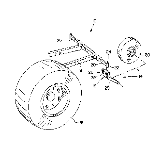
[0012] Fig. 1 is a perspective view of a portion of a work machine
incorporating an
embodiment of a suspension arrangement of the present invention;
[0013] Fig. 2 is a perspective view of the suspension arrangement illustrated
in Fig.
1;
[0014] Fig. 3 is a cross sectional view through the suspension arrangement,
taken
along line 3-3 in Fig. 2; and
[0015] Fig. 4 is a plan view of the torsion spring shown in Fig. 3.
Detailed Description of the Invention
[0016] Referring now to the drawings, and more particularly to Figs. 1 and 2,
there
is shown a portion of a work machine 10 incorporating an embodiment of a
suspension arrangement 12 of the present invention. Work machine 10 can be any
type of self-propelled work machine using one or more caster wheels, such as a
windrower, etc. In the embodiment shown, a portion of the lower part of a work
machine in the form of a windrower 10 is shown for illustration.
[0017] Windrower 10 includes a frame 14 carrying typical components (not
shown)
3

CA 02647635 2008-12-22
such as an operator's station, internal combustion engine, etc. A cutting
platform is
typically detachably mounted at the front end of the machine below the
operator's
station. The engine compartment is typically mounted behind the operator's
station
and above a pair of caster wheel assemblies 16. Only the left rear caster
wheel
assembly 16 is shown in Fig. 1 for simplicity, the right rear caster wheel
assembly
being configured substantially identical in the illustrated embodiment. Some
differences in the configurations of the caster wheel assemblies 16 are
possible, as
will be described in more detail below.
[0018] A pair of drive wheels 18 are carried by frame 14, and hydrostatically
driven
in known manner. It may be aiso possible to drive a single wheel 18, depending
upon the application.
[0019] Rear axle 20 may be a telescoping rear axle, as shown, and is rigidly
mounted to and substantially immovable relative to frame 14. Rear axle 20 need
not
be a telescoping axle. Rear axle 20 includes an outboard end carrying a collar
22
which pivotally couples with a corresponding caster wheel assembly 16, as will
be
described below.
[0020] Each caster wheel assembly 16 includes a pivotable shaft 24, a
suspension
26, a wheel arm 28 and a caster wheel 30 coupled with wheel arm 28. Shaft 24
is
rotatably carried within collar 22 which is welded or otherwise rigidly
affixed to frame
14. Wheel arm 28 is shown as a generally L-shaped single arm which curves
around to the side of wheel 30, thus putting whee130 generally in line with
shaft 24,
Wheel arm 28 can also be configured generally U-shaped as a fork with distal
ends
on opposite sides of wheel 30. The lower or distal end of wheel arm 28 carries
a
stub shaft (not shown), which in turn carries a wheel hub (not shown) for
mounting
wheel 30 in known fashion.
[0021] Referring to Figs. 2-4, conjunctively, suspension 26 interconnects
shaft 24
with wheel arm 28. Suspension 26 is configured with a torsion spring 32 but
could
possibly be configured with a different type of spring, depending upon the
application.
[0022] Torsion spring 32 includes an outer tube 34 with a square cross
section, an
inner member 36 with a square cross section, and a plurality of elastomeric
4

CA 02647635 2008-12-22
members 38 interposed between outer tube 34 and inner member 36. Outer tube 34
is shown coupled with shaft 24 and inner member with wheel arm 28, but it is
also
possible to couple outer tube 34 with wheel arm 28 and inner member 36 with
shaft
24.
[0023] Outer tube 34 is coupled with shaft 24 in an offset manner along a side
of
outer tube 34. Inner member 36 has an axis of rotation 40 which is generally
parallel to an axis of rotation 42 of caster wheel 30. Inner member 36
includes
opposite ends 44 which extend axially beyond the ends of outer tube 34. A pair
of
clamps 46 are rigidly connected (e.g., welded) with the upper surface of the
top,
horizontal portion of wheel arm 28. Each clamp 46 is clamped with a
corresponding
end 44 of inner member 36. Each clamp 46 includes a pair of support arms 48
which extend upwardly at an angle of approximately 45 relative to vertical.
This
splits forces applied by the ground into two component force vectors,
regardless of
whether the applied force is in a horizontal or vertical direction. The force
vectors
tangent to the axis of rotation 40 of inner member 36 assure that a rotational
force is
applied to torsion spring 32.
[0024] During operation, forces are applied by the ground to wheel 30. These
forces may generally either be parallel to the ground (such as an object
impinging
upon wheel 30), or in a vertical direction (such as a bump or the like). This
causes
wheel 30 to pivot in an arced manner about the axis of rotation 40 of inner
member
36, as indicated by the curved, double headed arrow 50 in Fig. 2. This
rotational
movement of wheel arm 28 carrying wheel 30 in turn compresses elastomeric
members 38 between inner member 36 and outer tube 34. This biases inner
member 36 back to the static position, and also damps vibrations which are
transferred to frame 14.
[0025] Having described the preferred embodiment, it will become apparent that
various modifications can be made without departing from the scope of the
invention
as defined in the accompanying claims.

Representative Drawing
A single figure which represents the drawing illustrating the invention.
Administrative Status

2024-08-01:As part of the Next Generation Patents (NGP) transition, the Canadian Patents Database (CPD) now contains a more detailed Event History, which replicates the Event Log of our new back-office solution.

Please note that "Inactive:" events refers to events no longer in use in our new back-office solution.

For a clearer understanding of the status of the application/patent presented on this page, the site Disclaimer , as well as the definitions for Patent , Event History , Maintenance Fee  and Payment History  should be consulted.

Event History

Description Date
Common Representative Appointed 2019-10-30
Grant by Issuance 2016-04-26
Inactive: Cover page published 2016-04-25
Inactive: Final fee received 2016-02-19
Pre-grant 2016-02-19
Notice of Allowance is Issued 2015-08-28
Letter Sent 2015-08-28
Notice of Allowance is Issued 2015-08-28
Inactive: Q2 passed 2015-06-30
Inactive: Approved for allowance (AFA) 2015-06-30
Amendment Received - Voluntary Amendment 2015-04-16
Inactive: S.30(2) Rules - Examiner requisition 2015-03-03
Inactive: Report - No QC 2015-02-23
Letter Sent 2014-01-15
Request for Examination Requirements Determined Compliant 2013-12-20
All Requirements for Examination Determined Compliant 2013-12-20
Request for Examination Received 2013-12-20
Application Published (Open to Public Inspection) 2009-07-03
Inactive: Cover page published 2009-07-02
Inactive: IPC assigned 2009-06-26
Inactive: First IPC assigned 2009-06-26
Inactive: IPC assigned 2009-06-26
Letter Sent 2009-03-23
Inactive: Office letter 2009-03-23
Inactive: Single transfer 2009-02-05
Inactive: Filing certificate - No RFE (English) 2009-01-26
Application Received - Regular National 2009-01-26

Abandonment History

There is no abandonment history.

Maintenance Fee

The last payment was received on 2015-12-02

Note : If the full payment has not been received on or before the date indicated, a further fee may be required which may be one of the following

  • the reinstatement fee;
  • the late payment fee; or
  • additional fee to reverse deemed expiry.

Patent fees are adjusted on the 1st of January every year. The amounts above are the current amounts if received by December 31 of the current year.
Please refer to the CIPO Patent Fees web page to see all current fee amounts.

Owners on Record

Note: Records showing the ownership history in alphabetical order.

Current Owners on Record
DEERE & COMPANY
Past Owners on Record
ALLAN WESLEY ROSENBALM
CHARLES SCOTT SLOAN
THOMAS DARYL BEBERNES
Past Owners that do not appear in the "Owners on Record" listing will appear in other documentation within the application.
Documents

To view selected files, please enter reCAPTCHA code :


To view images, click a link in the Document Description column (Temporarily unavailable). To download the documents, select one or more checkboxes in the first column and then click the "Download Selected in PDF format (Zip Archive)" or the "Download Selected as Single PDF" button.

List of published and non-published patent-specific documents on the CPD .

If you have any difficulty accessing content, you can call the Client Service Centre at 1-866-997-1936 or send them an e-mail at CIPO Client Service Centre.

({010=All Documents, 020=As Filed, 030=As Open to Public Inspection, 040=At Issuance, 050=Examination, 060=Incoming Correspondence, 070=Miscellaneous, 080=Outgoing Correspondence, 090=Payment})


Document
Description 
Date
(yyyy-mm-dd) 
Number of pages   Size of Image (KB) 
Description 2008-12-21 5 258
Abstract 2008-12-21 1 18
Drawings 2008-12-21 2 41
Claims 2008-12-21 3 106
Representative drawing 2009-06-07 1 12
Claims 2015-04-15 3 101
Representative drawing 2016-03-03 1 10
Filing Certificate (English) 2009-01-25 1 157
Courtesy - Certificate of registration (related document(s)) 2009-03-22 1 102
Reminder of maintenance fee due 2010-08-23 1 115
Reminder - Request for Examination 2013-08-25 1 117
Acknowledgement of Request for Examination 2014-01-14 1 175
Commissioner's Notice - Application Found Allowable 2015-08-27 1 162
Correspondence 2009-03-22 1 15
Final fee 2016-02-18 1 36