Note: Descriptions are shown in the official language in which they were submitted.
CA 02647948 2008-09-30
WO 2007/123815 PCT/US2007/008353
TITLE OF THE INVENTION
AXLE VENT
BACKGROUND OF THE INVENTION
The invention relates to the field of machinery venting. More specifically,
the invention provides a novel vent for an enclosure containing
lubricated machinery.
Gas-permeable, liquid-impermeable vents find use in many applications
in the automotive industry, such as electrical component housings, gear
housings, vehicle bodies, brake housings, etc. where pressure
equalization between the housing interior and surrounding environment
must occur. While vents must allow for gas pressure equalization, they
must also seal the interior of the housing from liquid, dirt and dust
particles. Failure to exclude liquids such as water can damage the
components and corrode the housing.
Machinery enclosures such as gearbox housings, axles and the like are
subject to thermal cycling. As the machinery is operated, temperatures
of the lubricant and internal air begin to rise, causing air pressure to rise
in the enclosure. When the machinery is stopped, pressure falls within
the enclosure. To accommodate changes in air pressure from operating
temperature changes, vents are required. If effective venting is not
provided, seals and gaskets may be compromised. It is important that
contaminants be prevented from entering the machinery enclosure.
Contaminants and water will severely degrade the effectiveness of
lubricant, which results in premature wear of the machinery.
Machinery vents have incorporated expanded Polytetrafluoroethylene
(ePTFE) membranes. Such membranes are known for water
1
CA 02647948 2008-09-30
WO 2007/123815 PCT/US2007/008353
impermeabily and air permeability and therefore not only prevent
contaminants from entering the gear case, but also contain the lubricant
to prevent spillage. However, ePTFE vents are subject to rapid blinding
as lubricant aerosol particles fill the membrane pores and block airflow.
Accordingly, known ePTFE vents had limited service life.
Other attempts at venting machinery spaces have incorporated baffles,
coalescing media or valve assemblies which permit expanding air to
escape through valve openings. During cooling periods, such
assemblies permit air ingress through a second valve assembly, or
through a membrane. Such assemblies necessarily incorporate
numerous moving parts which are subject to wear and have increased
assembly complexity.
Some machinery vents are mounted remotely from the machinery.
Remote mounting allows the vent to be placed in an area with limited
environmental exposure, and could reduce the problems associated with
lubricant blinding. Other gear cases incorporate a simple snorkel to vent
the case to a remote and relatively protected area. Such snorkels
provide little protection from contamination and will not prevent lubricant
spillage. Moreover, all remote mounting approaches introduce
additional parts cost and installation complexity.
What is needed is a vent without moving parts that can be mounted in
close proximity or directly to a machinery enclosure that allows adequate
air passage, prevents contaminants and liquid from entering the
machinery space, and retains liquids inside the enclosure in the event it
is oriented to allow liquids to contact the vent.
2
CA 02647948 2008-09-30
WO 2007/123815 PCT/US2007/008353
SUMMARY OF THE INVENTION
In one aspect, the invention provides a vented automotive gearcase
comprising a gear assembly disposed within a fluid-tight enclosure,
lubricant disposed within the enclosure, a passageway providing fluid
communication between the interior of the enclosure and the exterior,
gas permeable, water impermeable membrane covering the
passageway, and fibrous sorbent disposed within the passageway
between the lubricant and the ePTFE membrane.
In another aspect, the invention provides a vented machinery enclosure,
comprising a fluid tight housing defining an interior space and an exterior
space, the space containing lubricant, a vent comprising a body having a
passageway there through, a gas permeable, water impermeable
membrane covering the passageway, and a fibrous sorbent disposed
within the passageway and adjacent to the first side of said membrane,
the fibers of the sorbent having voids.
In a further aspect, the invention provides a vent for a machinery space,
the vent comprising a body having a passageway there through, gas
permeable, water impermeable membrane covering the passageway,
and fibrous sorbent disposed within the passageway between the
machinery space and the membrane.
In a still further aspect, the invention provides an improved vent for a
machinery enclosure of the type containing a passageway for the
passage of a gas between the interior of the enclosure and the ambient
air and a porous membrane sealing the passageway, the improvement
comprising fibrous sorbent disposed within the passageway between the
membrane and the interior of the enclosure.
In yet another aspect, the invention includes a method of venting a
machinery space of the type providing a passageway for venting a gas
from the interior of the machinery space and a porous membrane
3
CA 02647948 2008-09-30
WO 2007/123815 PCT/US2007/008353
covering the passageway, the improvement comprising a fibrous sorbent
between the membrane and the interior of the machinery space.
DESCRIPTION OF THE DRAWINGS
Figure 1 depicts a perspective view of one aspect of the inventive vent
Figure 2 depicts another embodiment of a vent according to the present
invention.
Figure 3 is a photograph showing the microstructure of cotton fiber.
Figure 4 is a photograph of a synthetic fiber with engineered surface
features.
Figure 5 is a chart depicting the airflow for various sorbent media.
Figure 6 depicts a schematic diagram of the apparatus use to test
venting performance.
DETAILED DESCRIPTION OF THE INVENTION
Definition of terms.
By "Absorption" is meant a process by which liquid or gas molecules are
taken up, or enter a bulk phase, this differs from adsorption because the
particles are taken up by a volume rather than by a surface. An
absorbent retains liquid or gas molecules by absorption.
By "Adsorption" is meant a process by which a liquid or gas molecules
accumulate on the surface of a solid. An "adsorbent" retains liquid or
gas molecules by adsorption.
4
CA 02647948 2008-09-30
WO 2007/123815 PCT/US2007/008353
By "Aerosol" is meant a gaseous suspension of fine (0.10 - 100 pm)
solid or liquid particles. An aerosol includes a mist, cloud, fog and the
like.
By "Oleophilic" is meant a material that has a surface with an affinity for
oil.
By "Gear Case" is meant as an axle, transmission, transfer case and
other assembly having lubricated moving parts generating shear forces
on the lubricant.
By "Hydrophobic" is meant materials that have a surface that is
extremely difficult to wet with water, with water contact angles in excess
of 90 .
By "Sorbent" is meant a solid material having the ability to retain gasses
or liquids; as used herein, Sorbent includes materials that are absorbent,
adsorbent or both.
The vent body of the present invention may be machined or cast from
metallic or polymeric materials. When used as an axle or automotive
machinery vent, the vent may be installed in a cast iron housing.
Accordingly, if metal vents are preferred, they may be machined from
stainless steel to avoid corrosion and bi metallic corrosion. Alternatively,
metal vents may be plated with zinc for example to inhibit corrosion.
Preferably, the bodies of the inventive vents are constructed from
polymeric materials. Polymeric vent bodies facilitate easy processing,
including heat sealing of the membrane to the body. Polymeric
materials are low cost and are not subject to corrosion. Most preferably,
the polymeric material is a polyamide. Polyamide 6.6 is ultimately
preferred because of its favorable cost and strength.
The vent body may be constructed in various shapes conducive to easy
installation in machinery housings. Those of skill in the art will
comprehend press in type vents, which seal by interference fit, threaded
vents, barbs, adhesives and other attachment means may be utilized
5
CA 02647948 2008-09-30
WO 2007/123815 PCT/US2007/008353
with due regard to the intended application. The form of the vent body is
not critical, provided that a through passageway extends through the
body to allow the passage of air.
In some applications, an elastomer is the preferred body material. The
compliance and resilience of such materials allow them to compensate
for tolerances in mating components such as these in the machinery
enclosure. In addition, in applications where impact from foreign objects
is possible, such materials can be less prone to damage or failure.
The passageway may be machined or cast within the vent body. While
many methods of providing the passageway are apparent, the vent body
is preferably cast or molded with a passageway there through to avoid
the additional processing of boring the body. The passageway defines a
volume sufficient to contain sorbent media. This volume may be defined
by a straight or tapered bore. Preferably, a counter bore may be
provided proximate to the head of the vent. The counter bore is
sufficiently voluminous to contain sorbent material, while the narrower
bore proximate to the machinery enclosure serves to contain the sorbent
material and provide the passageway from the machinery enclosure to
the sorbent.
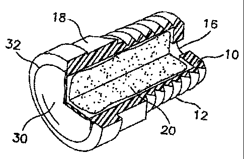
With reference to Figure 1, a vent body (10) is provided having a
passageway (16) there through. The body incorporates a threaded
portion (12) for insertion in a tapped hole in a machinery enclosure. The
body further includes a hexagonal portion (18) for driving the vent into
the tapped hole. Fibrous sorbent (20) is disposed within the
passageway. The open end of the passageway is covered by a
membrane (30) to prevent water from entering the enclosure- The
membrane is attached to the vent body by a heat seal (32).
It is desirable to prevent liquids lubricants within the machinery
enclosure from contacting the sorbent media. Accordingly, check, ball or
other one-way flow control devices (not shown) may be incorporated into
the passageway (16) of the vent body. Alternatively, the passageway
6
CA 02647948 2010-12-08
WO 2007/123815 PCT/US2007/008353
may incorporate a tortuous path therein to contain the lubricant and
prevent it from contacting the sorbent and or membrane.
The fibrous sorbent (20) effectively prevents membrane (30) from
blinding by reducing the amount of lubricant aerosol that contacts the
membrane, while maintaining adequate airflow for venting.
In another aspect, the body may be formed from, or consist entirely of,
the vent membrane or a laminate comprising the vent membrane. In this
embodiment, the membrane of laminate may be formed by thermal or
mechanical means to create a pouch for the sorbent. In this
embodiment, the flange of the membrane is sealed to encapsulate the
sorbent and provide a liquid tight seal.
With reference to Figure 2, fibrous sorbent (20) is disposed between two
layers of membrane (30). The one membrane includes a hole, which
provides a passageway (16). The vent may include adhesive media (31)
to attach the vent to a machinery housing.
During venting, air passes through inter-fiber void spaces of the sorbent.
Inter-fiber voids are necessary to maintain low pressure drop through the
sorbent. In one aspect, the invention provides a venting system having a
sorbent that maintains adequate inter-fiber void space. Sorption of oil
helps to maintain inter-fiber void space in the sorbent.
In a preferred aspect, the fibrous sorbent is comprised of fibers having
features which promote sorption of lubricant aerosols. Sorbent fibers
may be adapted to promote adsorption, absorption, and, preferably both.
Thus, in one aspect, the fibers may be adsorbent. Adsorbent fibers may
incorporate physical surface features such as twist, surface channels or
pores. These surface features tend to promote migration of oil along the
surface of the fiber. Distribution of oil droplets along the fibers helps to
prevent formation of large droplets and maintain inter-fiber void space
and may increase absorption rate.
7
CA 02647948 2008-09-30
WO 2007/123815 PCT/US2007/008353
In another aspect, the fibers may be absorbent. Absorbent fibers
include internal physical or chemical structure that promotes migration of
lubricant below the surface of the fiber, thereby preserving inter-fiber
void space and maintaining pressure drop across the sorbent. Physical
features promoting absorption include hollow lumen structures and
chemical compositions that promote oil absorption. In preferred
embodiment, the fibrous sorbent contains fibers that are hollow or
contain significant void spaces.
Many natural fibers have desirable oil sorption properties due to a
combination of effects. For example, cotton, kapok, milkweed, cellulose
and other fibers contain axial void spaces due to the progressive cellular
growth. Milkweed and kapok fibers have internal lumen structures in
which up to 90% of the fiber diameter is lumen. Cotton fibers also
contain significant void spaces that are distributed as concentric rings.
Such rings are visible in Figure 2. A single cotton fiber contains twenty
.to thirty concentric, hollow cellulose walls. Concentric rings and hollow
structures promote wicking of oil into and throughout the fiber.
Kapok fibers also include axial hollow space in the interstices of cellular
walls. The silky kapok fiber, or floss, is a tiny cellulose tube with air
sealed inside. Kapok fibers have closed ends. Kapok fiber is
considerably less dense than cotton fiber. Kapok is well known for
stuffing life preservers and other water-safety equipment because of its
excellent buoyancy. Kapok fiber is also lightweight, non-toxic, resistant
to rot and odorless. Significantly, Kapok can absorb as much as 30
times its own weight in liquid oil.
In one embodiment, the sorbent fibers comprise wool. Wool fibers have
an irregular, scaly surface, which may promote adsorption. The scaly
structure provides large and accessible surface pores for oil deposits.
Moreover, wool contains high quantities of surface wax. Naturally
occurring waxes may further contribute to oil sorption. Wax enhances
the sorbent-oil interactions through hydrophobic interactions and
improved oleophilic properties.
8
CA 02647948 2008-09-30
WO 2007/123815 PCT/US2007/008353
Moisture may interfere with the total sorption capacity of the sorbent.
Accordingly, in one aspect, the fibers of the sorbent are hydrophobic.
The fibers of the sorbent may also include synthetic fibers. Synthetic
fibers, such as polyester, polypropylene, nylon and acetate which have
an engineered surface profile, are effective. Super adsorbent fibers with
hydrophobic coatings may also have application as sorbents. Also,
hollow synthetic fibers may be useful in certain applications. Where
synthetic fibers are used, hydrophobic fibers are particularly preferred.
The fibers of the sorbent are most preferably oleophilic. Certain
synthetic fibers are oleophilic because of their chemical structures.
Oleophilicity enhances wicking, as well as surface transport of the oil
along the fiber surface and between fibers.
The sorbent is contained within the vent and protected from the exterior
environment by a membrane. The membrane may be of any material
that provides air permeability and liquid impermeability. Exemplary
membrane materials comprise polymers, for example polyethylene,
polypropylene or fluoropolymers. Coming into consideration as
fluoropolymers are tetrafluoroethylene/(perfluoroalkyl) vinyl ether
copolymers (PFA), tetrafluoroethylene/ hexafluoropropylene copolymers
(FEP) and polytetrafluoroethylene (PTFE), with preference to be given to
polytetrafluoroethylene, in particular expanded polytetrafluoroethylene
(ePTFE). The membrane material is porous and, depending on the
application area, may have pores of a size of from 0.01 to 20 m. Such
membranes are, by their nature, hydrophobic and are preferably
oleophobic. The membrane may be in the form of a laminate of
membrane and support material.
The support materials may include non-woven, melt blown, or scrim
polymeric materials. Preferably, these support materials have a
substantially open structure.
9
CA 02647948 2008-09-30
WO 2007/123815 PCT/US2007/008353
The membrane is secured to the vent body by an air and water tight
seal. In one aspect, the membrane includes a laminated layer of
adhesive and is heat-sealed to the vent. In another embodiment, the
membrane may be welded to the vent by ultrasonic welding.
Alternatively, the membrane is mechanically retained across the
passageway with a sealing ring or like means. The method of
attachment is not critical if an appropriately liquid proof and air tight seal
is maintained across the passageway. Preferably, the membrane is
heat sealed to the vent body.
Examples:
Example 1 of a vent according to the present invention was constructed
in the following manner: The vent body was machined from polyamide
6.6 in the general shape of a hollow threaded bolt. The body was
formed with a hexagonal shaped head of a width accommodating an
11/16th inch wrench. A 3/8th inch NPT tapered pipe thread was
machined into the vent body. A diameter hole drilled through the central
axis of the vent body and head provided a passageway through the vent
body. The passageway included a large counter bore through the head
portion of the vent. The counter bore volume was approximately 0.75 ml
and provided containment for the fibrous sorbent.
The fibrous sorbent comprised long natural Pima Cotton fibers. The
fibers were obtained from South Eastern Arizona Cotton Cooperatives,
250 mg of cotton is hand pressed into the counter bore cavity in the vent
body. A membrane covered the cotton sorbent.
The membrane was an approximately 8 (0) mil thick oleophobic ePTFE
membrane. The membrane had an air permeability of 8 Gurley, a water
entry pressure (WEP) of at least 3 psi. These membranes, as well as
other membranes useful in the present application are obtainable from
W. L. Gore and Associates, Inc., Elkton, Md. The membrane contains
the cotton fibers within the vent cavity. The membrane disk is heat
sealed to the vent body material using a copper sealing tool. The
CA 02647948 2008-09-30
WO 2007/123815 PCT/US2007/008353
sealing was performed by applying a force of 660 Newtons at 250 C for
1.0 second. Polyamides such as the material used for the vent body
contain significant moisture. Therefore, the body was dried in an oven
for approximately 12 hours at 125 C prior to welding.
Further examples were prepared using other sorbent media and different
sorbent media packing density. Example 2 was prepared according to
the description of Example 1; however, 0.2587 g natural cotton
adsorbent was disposed within the vent passageway. Example 3 was
prepared according to the description of Example 1; however, 0.2108 g
of FIT 4DG polyester fiber adsorbent was disposed within the vent
passageway. Comparative Example 4 was assembled without
adsorbent media.
Vent Longevity Testing:
Performance of the inventive vents was demonstrated using the
apparatus depicted schematically in Figure 6 and according to the
following experimental procedure:
An aerosol generator (40) (Nucon) was filled with a sufficient volume of
gear oil (42) (Lubrizol polyalphaolefin). Inlet pressure was established at
psi by supplying air at inlet (44) to generate an aerosol (46) challenge
20 rate of approximately 0.2mg/min with 99% of particles being less than 2
microns.
The vents to be tested were connected to the aerosol generator by a
0.25 inch diameter polypropylene airline (48). The airline and vent were
oriented vertically. The outlet of the vent was connected to an airflow
25 meter (50) by a 0.375 inch diameter polypropylene airline (49).
The 0.25 inch diameter polypropylene airline was first connected to a
clean air supply and the air flow was adjusted to generate a 0.19 psi
differential pressure across the test sample. The volumetric flow at 0.19
psi back pressure was recorded through the sample. The vent was then
connected to the aerosol generator, which was adjusted to provide the
11
CA 02647948 2008-09-30
WO 2007/123815 PCT/US2007/008353
same volumetric flow as the clean air source. Airflow was monitored
with a flowmeter (50) to determine the time at which airflow begins to
degenerate due to aerosol blinding of the ePTFE membrane. The time
verses airflow is reported in Figure 5.
Water Entry Pressure (WEP)
Water entry pressure provides a test method for water intrusion through
membranes. A test sample is clamped between a pair of testing plates.
The lower plate has the ability to pressurize a section of the sample with
water. A piece of pH paper is placed on top of the sample between the
plate on the nonpressurized side as an indicator of evidence for water
entry. The sample is then pressurized in small increments, waiting 10
seconds after each pressure change until a color change in the pH
paper indicates the first sign of water entry. The water pressure at
breakthrough or entry is recorded as the Water Entry Pressure. The test
results are taken from the center of test sample to avoid erroneous
results that may occur from damaged edges.
While particular embodiments of the present invention have been
illustrated and described herein, the present invention should not be
limited to such illustrations and descriptions. It should be apparent that
changes and modifications may be incorporated and embodied as part
of the present invention within the scope of the following claims.
12