Note: Descriptions are shown in the official language in which they were submitted.
CA 02648068 2008-10-01
WO 2007/120376 PCT/US2007/002680
WIRELESS LINKING OF SMOKE/CO DETECTION TJNITS
. ~ , .
BACKGROUND OF INVENTION
[00011 This invention relates generally to home alarm and detection units and,
more particularly,
to wireless linking of detection units.
[0002] There are various types of smoke and Carbon Monoxide (CO) detecting
devices that have
been developed, such devices typically being battery powered, hardwired or
wall-plug powered
units designed to sound an alann at the site of the detected smoke conditions.
Smoke detection
systems can include a plurality of detector units strategically positioned
throughout the monitored
area. Each of the plurality of detector units can include a detector for
sensmg one of a
characteristic andcondition within a section of the monitored area and
generating a signal
indicative of the monitored condition.
[0003] A signal processor or controller can be connected within each detector
unit for analyzing
the signal generated by the detector and upon determining if the signal is
above a predetermined
level generating an emergency signal. A transmitter can be provided for
transmitting the
emergency signal to a plurality of receiver units strategically positioned
about the monitoring -
area. Each receiver unit includes an alarm for generating an alarm signal and
thereby alert
persons to the emergency situation at a position within the monitored area.
The detector can be at
least one of a photoelectric smoke detector, an ionization type detector, a
combination carbon
monoxide and smoke detector, a carbon monoxide detector, a near-infrared
detector and a'hazard
detector. There are other types of environmental condition detectors such as
for example a
detector for high radioactivity conditions.
sTLDUI-1210462-1
CA 02648068 2008-10-01
WO 2007/120376 PCT/US2007/002680
[0004] However, in the past, these detection devices were not interconnected.
Such devices
however provide no warning to those out of the hearing range of the alarm
sensing an alert
condition. This obviously creates a substantial hazard to those in the same
house, building or .
-other structure who are not informed of the dangerous condition. Fire and the
resulting smoke
may unknowingly exist for significant periods of time in areas of buildings
before the occupants
are wamed tbrough conventional smoke detector systems where the detectors are
not
interconnected. Even with a plurality of conventional. smoke detectors,
occupants in remote '
locations of a burning building may not be able to audibly detect the local
alarm horn.
[0005] A need, therefore, existed for smoke detection systems that can
effectively provide early
warning to building occupants in remote locations or levels away from the
source=of the
smokelfire or other hazardous environmental condition and can provide a means
for lighted paths
of egress while doing so in a cost effective and simple manner. Such a system
needed to be easy
to install and operate for the average user.
[0006] Smoke detectors designed for remote sensing are commonly electrically
hardwired to a
central enunciator/controller panel to indicate the location of the smoke
within a building, which
affords a plurality of remote environmental condition detectors all exchanging
information
through a centralized control panel. In order to connect a plurality of the
prior art devices
together to provide a central indication of the location of the condition
sensed so as to enable the
provision of specific warning to all areas, or to enable steps to be taken to
abate the sensed
condition; it was previously necessary to physically interconnect an
enunciator panel with each of
the remote devices. This results in a costly system and required the use of
excessive wiring along
floors, walls or ceilings. Moreover, because each detection device typically
generated sound at
sTi.DOI-1210462-1 '
2
CA 02648068 2008-10-01
WO 2007/120376 PCT/US2007/002680
the detected location, the prior art devices were consumers of electrical
power and were often
unreliable and expensive. Installing and retrofitting of remote sensing smoke
detection systems
within buildings and residences without centralized enunciator panels is
greatly facilitated with
the wireless smoke detector system.
[0007] Many home fire and security alann systems, which'are often referred to
as a wireless
security system requires a hardwired keypad, a base station, a hardwired
siren, and AC power
connections. Such wireless systems actually require, therefore, considerable
wiring, which makes
them expensive to install and requires skilled installers. In an. effort to
reduce manufacturing and
installation costs, many designs combined the siren into the keypad and the
base station.
However, these systems are not usually installed by the average consumer.
[0008] In some alarm systems, the smoke detectors are battery operated and
include a smalI
transmitter that transmits a fire alann message to a*control panel. To sound
the alarm-throughout
the house, the control panel triggers a siren. When the alarm system is armed
and an actual alarm
condition is detected, prior systems sound the alarm throughout the house with
one or more
sirens. Each siren requires a separate installation and is usually wired in,
even in so-called
wireless systems. Because of the control panel installation and wiring
required, prior wireless
alarm systems are unduly complicated, especially for a typical homeowner to
install or service,
and do not have the benefits of typical hardwired systems. Accordingly, the
potential ofwireless
home fire alarm systems has not been realized.
[0009] Battery powered smoke detectors can be designed to be completely
wireless and to
provide an early warning of the presence of an environmental condition of fire
or smoke to
persons in remote areas of a building with respect to the location of the
environmental condition.-
sTLDO1-i210462-I
3
CA 02648068 2008-10-01
WO 2007/120376 PCT/US2007/002680
The smoke detector sensing the environmental condition can emit an audible
alarm of continuous
tone, while emitting a frequency modulated radio signal directly to other like
smoke detectors to
activate their alarms in a manner indicative of the location of the smoke
detector sensing the
environmental alarm condition. Rechargeable light modules separate from the
smoke detector are
included that receive the frequency modulated radio signal from the smoke
detector sensing the
environmental alarm condition and illuminate paths of egress for the duration
of the alarm
condition.
[0010] Traditionally to allow wireless alarms to communicate to one another
and discriminate
against neighboring alarms a dip switch (a switch that has multiple positions,
usually 8, which
can generate a binary number) is used to create a unique alarm ID(address or
house code). This
method works fine in principle but has the drawbacks of layout issues,
manually setting a random
number at the factory or by the customer.- cost of the switch, reliability of
the switch in corrosion
or manufacturing, number of unique ID's dependant on the number of switch
positions and.
additional circuitry needed to decode the switch to cut down on number of I/O
pins needed to
read the switch by the microcontroller. Also dip switches usually require
bottom mounting
which would require the units to be removed from the ceiling during the
installation period. Top
mounting of a dip switch would require a removable cover or door big enough to
be able to
access the dip switch or change the dip 'switch settings with a screw driver.
[00111 Attempts around the traditional dip switch method have been to use a
separate learn mode
switch to put the alarm in a learn mode, rolling -code encoder decoder
circuitry or prepacking a
set of alarms already configured to talk to one another. These attempts
although eliminating the
STLl3Ut-2210462-1
4
CA 02648068 2008-10-01
WO 2007/120376 PCT/US2007/002680
dip switch still require additional circuitry or the inflexibility of adding
or removing alarms from
the network.
[0012] There is a need for a Wireless smoke detection and alaxm system that is
easy to install and
resolves many of the above problems.
BRIEF SIJMMA1tY OF THE INVENTION
[0013] The invention is a wireless environmental condition detector and event
alarm system
comprising a controller operable to enter a teaching mode when a test button
communicably
linked to said controller is actuated after battery power has already been
engaged with the
controller and when it receives a wirelessly transmitted learner address
through a transceiver, to
wirelessly transmit a learn-my-code command and teacher house code data (house
code address)
to the wirele'ssly transmitted learner address, through the transceiver. The
controller is further
operable to enter a leaming mode when the test button is actuated and held
during engagement of =
battery power, and further operable to wirelessly transmit through the
transceiver a request
teaching command and the learner address; and fuither operable to receive the
learn-my-code
command and the teacher house code data and electronically store=said teacher
house code data.
This configuration allows the environment condition detector to link with
other detectors
configured with similar functionality.
[00141 The environment condition detectors are able to detect certain event
alarm environmental
conditions such'as smoke in the environment from a fire condition or carbon
monoxide in the
environment. Smoke detectors- and carbon monoxide detectors as well as other
types of
environment condition detectors can be within the scope of the present
invention, such as for
STI1)O1-1210462-1
CA 02648068 2008-10-01
WO 2007/120376 PCT/US2007/002680
example environment detectors for radioactivity, bacteria, biological and
chemical hazards and
other poisonous gases. Various environment condition detectors can be remotely
located with
respect to each other and linked together by using the learn and teach modes.
The environment
condition detectors and all its functionality as described herein and as
depicted in Fig. 5 can
simply be referred to as a detector. Various remote detectors can be generally
referred to as units
and in order to distinguish between the units they can be generally referred
to as units A, B, C...
or units 1, 2, 3, ... When multiple units are linked together so that they can
communicate
information to linked units having a Iike house code address as in the present
invention, the
linked units can be generally referred to as a environmental condition
detector network or system.
(0015] Another embodiment of the present invention is a method of implementing
a wireless
environment condition detector and alarm comprising the steps of initiating a
teach mode of acontroller of a detector when a test button communicably linked
to said controller is actuated
after battery power has already been engaged with the controller, where said
teach mode fiuther comprises the steps of, receiving a wirelessly-transmitted
learner address through a transceiver
and wirelessly transmitting a learn-my-code command and teacher house code
data to the
wirelessly transmitted learner address, through said transceiver. The method
further includes
initiating a learn mode of a controller when the test button is actuated
during engagement of
battery-power, where said learn mode further comprises the steps of wirelessly
transmitting
through said transceiver a request teaching command and the learner address,
and receiving the
learn-my-code command and the teacher house code data and electronically
storing said teacher
house code data.
sTLD01-1210462-1
6
CA 02648068 2008-10-01
WO 2007/120376 PCT/US2007/002680
[0016] This invention solves the above issues by providing an easy method of
learning and
unZearning for an environment condition detector to network to one another
without the need for
a dip switch or any additional circuitry or interconnect wiring. The method
starts by having the
alarm generate its own random number address (or house code) during factory
testing and then
storing it in nonvolatile memory. When the alarms leave the factory the alarms
should not
communicate to one another. To link or create a network of alarms the customer
first instails the
batteries in any one of the alarms and closes the battery drawer for normal
operation.
[0017] Next the batteries are put into one of the other environment condition
detectors to be
linked or networked and the test button is actuated and held while the battery
drawer is being
closed or while battery power is engaged with the controller of the unit. When
a chirp is heard
the test button is released and a LED starts'flashing rapidly indicating the
unit is now in a learn
rhode and starts sending out a request teaching command with its remote
Iearner address (or
house code). -The customer now presses the test button of the normal operation
environment
condition detector or detector in which to network to, which listens for a
request teaching
command before going into a test mode. If it hears a request teaching command
it sends a learn-
my-code command along with its house code to the remote Ieamer address instead
of going into
test mode. The leam mode detector receives the Iearn-my-code command and
replaces its
address (or house code) with the teacher's house code and then stops flashing
the LED and issues
a welcome chirp and goes into normal operation mode.
[0018] To unlink any alarm from the network the customer removes power or
disengages battery
power from a networked unit and then reapplies power with the test button held
and listens for a
chirp and then releases the test button putting the alarm into the learn mode.
When in Ieam mode
STLDOI-1210462-1
7
CA 02648068 2008-10-01
WO 2007/120376 PCT/US2007/002680
a random number generator is always going and if the customer presses the test
button again on
the detector in learn mode instead of any of the other detectors in the
network (or teachers) the
learner detector will replace its house code with a new randomly generated
randomized house
code:
[0019] In the case of the customer market, this invention provides lower cost
solution and more
secure method of creating a network by ensuring a random unique house:code is
generated when
networking detectors together. Enhanced variations may include using multiple
environment
sensors and voice output.
[0020] These and other advantageous features of the present invention will be
in=part apparent
and in part pointed out herein below.
BRIEF DESCRIPTION OF THE DRAWINGS =
[0021] For a better understanding of the present -invention, reference- may be
made to the
accompanying drawings.
(0022] Figs. 1, 2, 3, and 4 are the functional flow diagrams of the wireless
system.
[0623J Fig: 5 is a functional diagram of the wireless -environmental.
condition detector system.
DETAILED DESCRIPTION OF INVENTION
[0024] According to the embodiment(s) of the present invention, various views
are illustrated in
Fig. 1-5 and like reference numerals are being used consistently throughout to
refer to like and
correspondipg parts of the invention for all of the various views and figures
of the drawing.
S'CL..DOI-1210462-1
8
CA 02648068 2008-10-01
WO 2007/120376 PCT/US2007/002680
Also, please note that the first digit(s) of the reference number for a given
item or part of the
invention should correspond to the Fig. number in which the item or part is
first identified.
[0025] One embodiment of the present invention comprising environmental
condition detectors
operable to link forming a network teaches a novel apparatus and method for
networking smoke
detectors and other environmental detectors.
[00261 The details of the invention and various embodiments can be better
understood by
referring to the figures of the drawing. Referring to Figs. 1-5, a functional
diagraam illustrating an
environmental condition detector with some of the primary components is shown.
The
environmental condition detector (detector) is shown having a controller 502
which controls the
major functions of the environment:al condition detector as well as
controlling the transmission of
wireless outputs as well as receiving and interpreting wireless input
transrnissions. The
controller electronically interfaces with the other major functions of the
environmental condition
detector 500. The environmental condition detector includes a battery power
source. 504 that is
operable to engage the detector thereby engaging power to the unit's major
components such as
the controller and the sensor,=which senses for hazardous environmental
conditions such as
smoke in the air. The controller can be- a typical micro-processor or signal
processor.
[0027] The battery power source 504 is further operable to be disengaged for
renioving power
from the unit. The battery power source can simply be a drawer mechanism with
=a battery
installed such that when the drawer is pushed into the unit, the battery
electrically engages the
unit and its components. When the drawer is pulled out, the battery power is
disengaged from
the unit. Other engagement and dis-engagement mechanisms can be utilized
without departing
from the scope of this invention. The environmental condition detector unit
also includes a test
STLDOI-1210462-1
9
CA 02648068 2008-10-01
WO 2007/120376 PCT/US2007/002680
button interface 506 which is operable to be actuated to initiate a test mode
for the unit or to
initiate a learn or teach mode for the unit. What the actuation of the test
button initiates depends,
on whether battery power is engaged and whether a request teaching mode
command is detected
as described further herein.
[0028] The unit also includes memory 508 for electronically storing house code
addresses or the
learneraddress. The controller is operable to store data to the memory
function as well as
retrieve information from the memory function. The house code address stored
in memory
determines whether a unit will be able to communicate with another unit. If
units have the same
house codes then they can conununicate. The environmental condition detector
also includes an
environmental condition sensor 510. This sensor can be operable to detect
smoke and/or carbon
monoxide or some other hazardous environrnental condition. The sensor can be
operable to,
sense for certain conditions such that when the environniental conditions
reach a certain level an
event alarm signal can be activated notifying the controller that an alarm
event has occurred. The
controller 502 is further operable to control an alert indicator function 512
such that when a
sensor activates an event alarm signal, the controller can in turn activate
the alert indicator 512 to
signal that an alarm event has occurred. The alert indicator can be an audible
alarm such that the
controller sounds an event alarm or some other type of alarm indicator
function. The
environmen#al condition detector unit 500 also includes a wireless transceiver
encoder/decoder
function for wirelessly transmitting information such as an event alarm
transrnission, a house
code address or a command data transmission relating to learning and teaching
for linlcing
multiple units in a network, such as for example a request teaching command or
a learn-my-code
command.
sTLDOt-1210462-1
CA 02648068 2008-10-01
WO 2007/120376 PCT/US2007/002680
[0029] The controller of the unit can be operable to distinglzish between
various types of event
alarm transmissions. For example an event alarm transmission for smoke
condition can be
distinguishable from an event alarm transmission for a carbon monoxide
condition. Therefore,
the detectors can also be equipped with multiple alert indicators such as for
example separate
alert indicators for smoke conditions and carbon monoxide conditions. Also,
one alert indicator
such as an audible alarm can be utilized but different alarni patterns can be
utilized depending on
the condition.
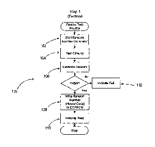
.[00301 The factory setup flow 100 is shown in Fig. 1. The factory test
routine can be initiated by
starting a random number generator as represented by functional block 102
which generates a
random number for the house code of the unit which will be stored in memory.
The test circuitry
can be exercised as part of the factory setup as indicated by functional block
104. ORentimes as
pairt of the factory setup the sensors require calibration as represented by
functional block 106. If
the unit- passes the factory setup the random number house code is stored in
memory as
represented by functional block 108.
[0031] Referring to Figs. 2, 3 and 4, flow diagrams are provided that
illustrate the operation of an
environmental condition detector during power up as well as during the learn
mode, teach mode,
normal operation mode and test mode. Fig. 2 reflects the operational flow of a
unit A 202 as it
transitions through the teach process. The process begins with the
installation of the battery
power and the engaging. of the battery power with the environmental condition
detector unit as
reflected by functional blocks 204 and 206. Upon engagement of the battery
power, the
controller of the environmental condition detector unit determines whether the
test switch (test
button) has been actuated: This determination process is reflected by decision
block 208.
STLDOI-1210462-1 '
11
CA 02648068 2008-10-01
WO 2007/120376 PCT/US2007/002680
[0032] If the test switch is actuated upon engagement of the battery power
then the controller
would place the detector unit'into the learn mode as reflected by functional
block 220. If the test
switch is not actuated upon engagement of the battery power, then the
controller will place the
unit in a listen mode for capturing incoming wireless transmissions as
reflected by functional
block 210. The unit will also transition into the normal operation mode as
reflected by functional
block 212 in which the unit will begin sensing for event alarm conditions such
as for example
smoke in the air or= carbon monoxide. The unit will continue to determine and
monitor whether
an alarm event has occurred as reflected by functional block 214. An alarm
event can occur as a
result of the sensor internal to the unit sensing an alarm event condition
thereby sending a signal
to the controller module which in turn activates the alarm mode thereby
activating the alarm
indicator as reflected by functional block 222.
[0033] Altematively, the environmental detection unit can sense a wireless
transmission of an
alarm event from another unit that is communicably linked in a network
environment (having the
same house code address). Again, if the unit detects an alarm event
transmission, the controller
will place the environmental condition detector unit into the alarm mode.
[0034] If the test button is actuated during normaI operation, the
environmental condition
detector unit will enter into a listening mode to determine if a request
teaching command is
requested from another unit as reflected by functional block =234. If a
request teaching command
is not detected, then the environmental condition detector unit will default
to the test mode as
determined by functional block 234. During test mode the unit can test its
intemal circuitry as
= i
well as possibly sounding an alarm thereby confirming operation of the alarm
system.
STI.i?o2-1210452-1
12
CA 02648068 2008-10-01
WO 2007/120376 PCT/US2007/002680
[0035] If a request teaching command is received, then the environmental
condition detector unit
will enter into the teaching mode as referred to by functional block.226 and
228. The controller
for the environmental condition detector unit will process the request
teaching command and will
control the transceiver to transmit its house code address (teacher house code
address or first unit
house code address) and a leam-my-code command. This transmission is sent to
the learner's
address as reflected by functional block 230.
[0036] Referring to Fig. 3 and Fig. 4, a flow diagram is shown reflecting the
fiuactional flow of
networking units B, C and etc. 302 to unit A. Again, the subsequent units are
initialized by
installing the battery in the drawer of the environmental condition detector
unit.as reflected by
functional block 304. However, prior to engaging the battery power to the
unit, the installer will
actuate and hold the test button and then engage the battery power to the unit
as reflected by
functional blocks 306 and 308. When the unit signals with a confirmation
indicator such as an
audible chirp, the installer can then release the-testbutton as reflected by
functional block 310.
The unit can optionally have an LED light that flashes rapidly indicating that
the unit is entering
the learn process (leam mode) and the random number generator process as
reflected by
functional blocks 312 and 314.
[0037] The controller will then place the environmental condition detector
unit in the learn mode
and will control the transceiver module to transmit a request teaching command
with the house
code address (learner's house code address or 2"a , 3id or ... unit house code
address) of the unit
that is now in the leam mode. After the'transmission, the controller will then
control the unit to'
listen for a learn-my-code command to be transmitted by a unit that is now in
the teaching mode.
If there is a unit that is transrnitting a learn-my-code command and is in the
teaching mode,.the
STLA01-1210462-1
13
CA 02648068 2008-10-01
WO 2007/120376 PCT/US2007/002680
teaching mode unit will also transmit the teacher's house code address to be
received by the .
second unit and such teacher's house code address. will now be utilized by the
second (leamer)
unit being installed that is now in the learner mode.
[0038] . If the learn-my-code command is received by the second (learner) unit
that is now in the
learning mode, it will then replace its current house code address with the
house code address
that was received through the transmission from the teachiing unit (teachei
house code address or
lst unit house code address). The house code address of the teacher unit is
stored in memory of
the second unit as reflected by functional block 322. If alearn-my-code
command is not received
from a teaching unit, then the unit that is now currently in learn mode will
determine whether the
test button has been actuated. If the test button is actuated, then the
learning unit will then
replace.its current house code address with the new random number (randomized
house code)
and stbre the new random number in memory. If at this stage the test button is
not actuated, the
unit that is now in the leam mode will again re-transmit a request teaching
coinmand. A timer
can be utilized so that the detector does not remain in the learn mode
indefinitely awaiting a
leam-my-code command or a test button actuation for -randomization. A timer
can be utilized to
determine if a predetermined time had elapsed since entering the learn mode
without receiving a
leam-my-code command nor a test button actuation thereby tinling out. If a
time out occurs,
block 360, the detector will enter normal operation. Once the new house code
address has been
stored in memory the controller can then turn off the rapidly flashing LED-and
can issue another
audible chirp or other confirmation as reflected by functional block 330. At
this point, the unit
will now enter into the listen to RF and normal operation mode. The unit will
then operate in a
manner like that shown in the functional flow of Fig. 2 where the unit will
monitor for alarm
STLDOI-1210462-1
14
CA 02648068 2008-10-01
WO 2007/120376 PCT/US2007/002680
events as well as monxtoring for test button actuation for entry into a test
mode or a teaching
mode.
[0039] Subsequent units can be linked in a similar manner. Once the units are
linked they can
communicate infonnation based on the common house code address.
[0040] The various.wireless detector system examples shown above illustrate a
novel system and
method for a wireless smoke detector system. A user of the present invention
may choose any of
the above wireless systems, or an=equivalent thereof, depending upon ttie
desired application. In
this regard, it is recognized that various forms of the subject wireless
detector system could be
utilized without departing from the spirit and scope of the present invention.
[0041] It isevident from the foregoing description, certain aspects of the
present invention are
not limited by the particular details of the examples illustrated herein, and
it is therefore
contemplated that other modifications and applications, or equivalents
thereof, will occur to
those skilled in the art. It is accordingly intended that the claims shall
cover all such
modifications and applications that do not depart from the sprit and scope of
the present
invention.
[0042] Other aspects, objects and advantages of the present invention can be
obtained from a
study of the drawings, the disclosure and the appended claims.
STE.DOI-1210462-1
~S