Note: Descriptions are shown in the official language in which they were submitted.
CA 02648201 2008-10-02
WO 2007/121043 PCT/US2007/064976
SYSTEM, METHOD, AND COMPUTER READABLE MEDIA FOR
ADAPTIVELY DETERMINING A BRAKE APPLICATION LEVEL FOR
SIGNALING A REMOTE LOCOMOTIVE OF A TRAIN DURING A
COMMUNICATION LOSS
This application claims priority based on U.S. Provisional Application
No. 60/792,888 filed April 18, 2006, which is incorporated herein by
reference.
FIELD OF THE INVENTION
Embodiments of the present invention relate generally to the field of
locomotive
control, and more particularly to a method of adaptively determining a brake
application level for signaling a remote locomotive of a train during a
communication
loss.
BACKGROUND OF THE INVENTION
Distributed power train operation supplies motive power from a lead locomotive
and
one or more remote locomotives spaced apart from the lead locomotive in a
train
consist. Each lead and remote locomotive includes an air brake control system
for
controlling braking operations and a communication system for exchanging
information between lead and remote locomotives over a communication link. A
brake pipe fluidically interconnects each of the locomotives and rail cars of
the train
wherein modulation of a fluid flow, such as a fluid pressure in the brake
pipe, is
conventionally used to indicate desired braking operations. Brake application
is
typically accomplished by venting, or reducing a pressure in the brake pipe.
However,
brake pipe venting at only the lead locomotive of a train requires propagation
of the
corresponding brake pipe pressure reduction along the length of the train,
thus
slowing brake application at rail cars and remote locomotives near the end of
the
train. In distributed power trains, braking is more effectively accomplished
by
venting a brake pipe at both the lead and remote locomotives of the train,
thus
accelerating the brake pipe venting and the application of brakes throughout
the train.
1
CA 02648201 2008-10-02
WO 2007/121043 PCT/US2007/064976
For distributed power trains with an operative communication link between a
lead and
remote locomotives, wireless traction and braking commands are typically
transmitted
to each remote unit over the link, such as when a train operator at the lead
commands
a brake application. For example, in response to a wireless brake application
command, each remote locomotive also vents the brake pipe. Similarly, a brake
release initiated at the lead is also communicated over the radio link, and
each remote
may respond by releasing its brakes and charging the brake pipe.
In the event that radio communication becomes inoperable in a distributed
power
train, it may be desired to command a remote locomotive experiencing a radio
communication loss to enter a fail safe mode of operation, such as disabling
charging
or venting of the brake pipe at the remote, and/or reducing a traction
condition of the
remote. Such a fail safe state may be initiated by applying the brakes at the
lead
locomotive to generate a brake pipe brake application signal propagated along
the
brake pipe to the remote locomotive. For example, when a communication loss
condition is indicated at a lead locomotive, such as via a communication loss
indicator
at a control panel of the lead locomotive, the operator of the lead locomotive
may
command a fail safe state by applying a minimum brake application to the train
via
the brake pipe. The minimum brake application signal propagated along the
brake
pipe from the lead locomotive is then interpreted as a command to suspend
brake pipe
charging and/or enter an idle traction state at the remote locomotive.
BRIEF DESCRIPTION OF THE INVENTION
In one embodiment, the invention includes a method for adaptively determining
a
brake application level for signaling a remote locomotive of a railroad train
during a
communication loss, the railroad train having a brake system including a fluid
carrying brake pipe having an exhaust and connecting a lead locomotive and at
least
one remote locomotive, the railroad train further comprising a communication
system
for communicating between the lead locomotive and the remote locomotive. The
method includes determining a brake system operating condition of the train
and
determining an operability condition of the communication system. The method
also
includes identifying an operator commanded brake application level at the lead
2
CA 02648201 2008-10-02
WO 2007/121043 PCT/US2007/064976
locomotive during a communication system inoperability condition. The method
further includes determining a signaling brake application level sufficient
for
signaling the remote locomotive via the brake pipe responsive to at least one
of the
brake system operating condition, the operability condition of the
communication
system, and the operator commanded brake application level.
In another embodiment, the invention includes a system for adaptively
determining a
brake application level for signaling a remote locomotive of a railroad train
during a
communication loss, the railroad train having a brake system including a fluid
carrying brake pipe having an exhaust and connecting a lead locomotive and at
least
one remote locomotive, the railroad train further comprising a communication
system
for communicating between the lead locomotive and the remote locomotive. The
system includes a first sensor for determining a brake system operating
condition of
the train and a second sensor for determining an operability condition of the
communication system. The system also includes a third sensor for identifying
an
operator commanded brake application level at the lead locomotive during a
communication system inoperability condition. The system further includes a
controller in communication with the first, second, and third sensors and
configured
for determining a signaling brake application level sufficient for signaling
the remote
locomotive via the brake pipe responsive to at least one of the brake system
operating
condition, the operability condition of the communication system, and the
operator
commanded brake application level
In another embodiment, the invention includes computer readable media
containing
program instructions for adaptively determining a brake application level for
signaling a remote locomotive of a railroad train during a communication loss,
the
railroad train having a brake system including a fluid carrying brake pipe
having an
exhaust and connecting a lead locomotive and at least one remote locomotive,
the
railroad train further comprising a communication system for communicating
between
the lead locomotive and the remote locomotive. The computer readable media
includes a computer program code for determining a brake system operating
condition
of the train and a computer program code for determining an operability
condition of
the communication system. The computer readable media also includes a computer
3
CA 02648201 2008-10-02
WO 2007/121043 PCT/US2007/064976
program code for identifying an operator commanded brake application level at
the
lead locomotive during a communication system inoperability condition. The
computer readable media further includes a computer program code for
determining a
signaling brake application level sufficient for signaling the remote
locomotive via the
brake pipe responsive to at least one of the brake system operating condition,
the
operability condition of the communication system, and the operator commanded
brake application level.
BRIEF DESCRIPTION OF THE DRAWINGS
These and other features, aspects, and advantages of the present invention
will
become better understood when the following detailed description is read with
reference to the accompanying drawings in which like characters represent like
parts
throughout the drawings, wherein:
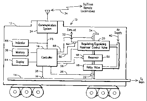
FIG. 1 is a schematic diagram of an exemplary system for adaptively
determining a
brake application for signaling a remote locomotive of a distributed power
train
during a communication loss; and
FIG. 2 is a flow chart of an exemplary method for adaptively determining a
brake
application for signaling a remote locomotive of a distributed power train
during a
communication loss.
DETAILED DESCRIPTION OF THE INVENTION
The present inventors have observed in a distributed power train operating
with a
communication loss condition that if a brake pipe has not charged sufficiently
from a
previous braking state, a brake application made by the operator of the lead
locomotive to command a remote locomotive to enter an idle down state and/or
suspend brake pipe charging may not be propagated over a brake pipe to the
remote
locomotive. Consequently, during the communication loss period, the remote
locomotive may remain in traction and/or a brake charging state that may
result in
undesirably long stopping distances, excessively high in train forces, etc. To
compensate for the above problem, a train operator needs to assess a train
length and
4
CA 02648201 2008-10-02
WO 2007/121043 PCT/US2007/064976
configuration, determine if the train brakes are applied or released, and
evaluate a
state of charging condition of the brake pipe to determine an amount of brake
pipe
pressure reduction that is needed to achieve a desired traction and/or
charging
condition at the remote locomotives of the train during a communication loss
condition. The inventors have developed an innovative scheme that relieves the
operator from having to evaluate train configuration and train operating
parameters to
determine a brake application level sufficient for signaling the remote
locomotive to
achieve a desired operating condition of the remote locomotive.
FIG. 1 is a schematic diagram of an exemplary system 10 for adaptively
controlling a
brake application for signaling a remote locomotive from a lead locomotive 12
of a
train, such as a distributed power train, during a communication loss. The
system 10
may include a regulating/equalizing reservoir control valve 20 receiving an
air supply
40. The regulating/equalizing reservoir control valve 20 may be operable to
selectively vent air, via exhaust port 52, and supply air via a fluid
connection to a
reservoir 50 to control application and release of the train brakes. The
reservoir 50
may also provide air to a relay valve 18 that also receives air via air supply
40. The
regulating/equalizing reservoir control valve 20 may be controlled by a
manually
operated brake handle 54 and/or may be automatically controlled to selectively
vent
air or supply air to the equalizing reservoir 50 which in turn controls the
brake pipe 14
via the relay valve 18 to achieve a desired level of brake application or
brake release.
The system 10 may also include a communication system 24, such as a wireless
communication system, for communication with one or more remote locomotives
(not
shown) of the train via communication link 34. The communication system 24 may
generate a communication operability status signal 28 from the communication
system 24 indicating whether or not the wireless link 34 is operable for
communicating with one or more remote locomotives of the train. An indicator
66
may receive the communication operability status signal 28 and generate an
indication, such as a visual and /or aural indication, to an operator
responsive to the
communication operability status signa128.
CA 02648201 2008-10-02
WO 2007/121043 PCT/US2007/064976
In an aspect of the invention, the system 10 includes a controller 16
receiving a fluid
flow signal 26 from a fluid flow sensor 22. The fluid flow sensor 22 monitors
a
condition of the brake pipe fluid flow, such as fluid flow into the brake pipe
14 at the
lead locomotive 12, and generates a fluid flow signa126 responsive to a sensed
fluid
flow condition. The controller 16 may also receive a fluid pressure signal 36
from a
fluid pressure sensor 32. The fluid pressure sensor 32 may monitor a condition
of
brake pipe fluid pressure, such as fluid pressure in the brake pipe 14 at the
lead
locomotive 12, and generate the fluid pressure signal 36 responsive to a
sensed fluid
pressure condition. The brake pipe fluid pressure may be indicative of a brake
application level commanded at the lead locomotive 12. The controller 16 may
also
receive a reservoir pressure signa156 responsive to a fluid pressure in the
reservoir 50
from a reservoir pressure sensor 58. The controller 16 may also receive an
exhaust
flow signa160 responsive to an exhaust flow from the regulating / equalizing
reservoir
control valve 20 from an exhaust flow sensor 62. The controller 16 may also
receive
the communication operability status signal 28 from the communication system
24
indicating whether or not the wireless link 34 is operable for communicating
with one
or more remote locomotives 12 of the train. The controller 16 may also receive
a
brake application state signal, for example, responsive to a position of the
brake valve
handle 54, indicative of an operator commanded brake application or release.
Controller 16 may take any form known in the art, for example, an analog or
digital
microprocessor or computer, and it may be integrated into or combined with one
or
more controllers used for other functions related to the operation of the lead
locomotive 12.
In an embodiment of the invention, the controller 16 may be configured for
providing
an adaptive brake application control scheme for signaling a remote locomotive
of a
distributed power train during a communication loss via the brake pipe. The
scheme
may include automatically controlling a brake application and/or providing
indicia to
an operator of the train to be used to control a brake application. For
example, the
controller 16 may be configured to implement steps for determining a brake
application sufficient for signaling a remote locomotive to reduce a tractive
effort
and/or limit charging of the brake pipe at the remote locomotive during a
6
CA 02648201 2008-10-02
WO 2007/121043 PCT/US2007/064976
communication loss state. Based on the determined sufficient brake
application,
when an operator commands an insufficient braking application during the
communication loss, the controller 16 may notify the operator, for example,
via
display 64 that an additional braking application needs to be applied to
ensure a brake
signal is propagated to the remote. In another embodiment, the controller 16
may
automatically control a brake application based on the determined sufficient
brake
application to ensure that a sufficient break application is commanded. The
steps
necessary for such processes may be embodied in hardware, software and/or
firmware
in any form that is accessible and executable by processor 16 and may be
stored on
any medium that is convenient for the particular application, such as memory
38.
As shown in the flow chart 70 of FIG. 2, the steps may include determining a
brake
system operating condition of the train 72 and determining an operability
condition of
the communication system 74. The steps may also include identifying an
operator
commanded brake application level at the lead locomotive during a
communication
system inoperability condition 76. The steps may then include determining a
signaling brake application level sufficient for signaling the remote
locomotive via the
brake pipe responsive to at least one of the brake system operating condition,
the
operability condition of the communication system, and the operator commanded
brake application level.
To perform these steps, the controller 16 of FIG. 1 may be configured for
monitoring
a braking state of the train, such as a brake application state or a brake
release state,
and/or duration of the braking state. The controller 16 may further monitor
respective
operating conditions of elements of the train brake system, such as by
monitoring
signals 26, 36, 60, and 56. During a communication loss state indicated, for
example,
by the communication operability status signal 28, the controller 16 may use
the
monitored braking state and monitored signals to determine an appropriate
brake
application for reliably commanding an operating condition of the remote
locomotive
via the brake pipe 14.
In an example embodiment, when a communication loss occurs during a brake
release
state, the controller 16 may be configured to provide a brake application
level based
7
CA 02648201 2008-10-02
WO 2007/121043 PCT/US2007/064976
on a value of the brake flow signal 26. The controller 16 may be configured
for
generating a smaller application for a relatively smaller sensed flow, and
generating a
larger application for a relatively larger sensed flow. Generating may include
providing an indication of an appropriate brake application level and/or may
also
include automatically applying the appropriate brake application level. For
example,
when a sensed flow of less than about 20 cubic feet per minute (cfin), a
minimum
service application of about 7 pounds per square inch (psi) may be generated
as
sufficient for ensuring the resulting brake pipe signal is propagated to the
remote
locomotive. Accordingly, if the operator has made a minimum service
application,
additional brake application may not be needed. For a sensed flow of between
about
20 cfm and about 60 cfin, a full service application of about 15 psi may be
generated.
Accordingly, if the operator has only made a minimum service application, an
additional brake application of about 8 psi may be needed. For a sensed flow
greater
than about 60 cfm, an emergency application may be generated.
When a communication loss occurs during a brake application state, the
controller 16
may be configured to generate a brake application level based on a level of
brake
application commanded by the operator, a time elapsed since brake application,
and/or a brake pipe exhaust flow. For example, for a brake application of less
than
about 16 psi, and when more than about 90 seconds has elapsed from the
initiation of
the brake application when the communication loss occurs, and when brake pipe
exhausting has stopped, for example, when the exhaust flow is about 0 cfin, a
supplemental brake application of about 10 psi may be generated by the
controller 16.
When less than about 90 seconds has elapsed since initiation of a brake
application
when the communication loss occurs, or when the brake pipe is exhausting, or
when a
brake application of greater than 16 psi has been applied, an emergency brake
application may be generated by the controller 16.
In another exemplary embodiment of the invention, the system 10 may include
memory 38 storing a braking schedule comprising a plurality of brake
application
levels corresponding to a brake application and operating parameters of the
train
braking system. The controller 16 may include logic executable for accessing
the
braking schedule stored in the memory 38 for adaptively determining a brake
8
CA 02648201 2008-10-02
WO 2007/121043 PCT/US2007/064976
application level for signaling a remote locomotive of a distributed power
train during
a communication loss. In an aspect of the invention, the braking schedule may
embody the brake application levels responsive to operating parameters of the
train
braking system as described previously.
Based on the foregoing specification, the invention may be implemented using
computer programming or engineering techniques including computer software,
firmware, hardware or any combination or subset thereof, wherein the technical
effect
is to adaptively determine a brake application level for signaling a remote
locomotive
of a distributed power train during a communication loss. Any such resulting
program, having computer-readable code means, may be embodied or provided
within
one or more computer-readable media, thereby making a computer program
product,
i.e., an article of manufacture, according to the invention. The computer
readable
media may be, for instance, a fixed (hard) drive, diskette, optical disk,
magnetic tape,
semiconductor memory such as read-only memory (ROM), etc., or any
transmitting/receiving medium such as the Internet or other communication
network
or link. The article of manufacture containing the computer code may be made
and/or
used by executing the code directly from one medium, by copying the code from
one
medium to another medium, or by transmitting the code over a network.
One skilled in the art of computer science will easily be able to combine the
software
created as described with appropriate general purpose or special purpose
computer
hardware, such as a microprocessor, to create a computer system or computer
sub-
system embodying the method of the invention. An apparatus for making, using
or
selling the invention may be one or more processing systems including, but not
limited to, a central processing unit (CPU), memory, storage devices,
communication
links and devices, servers, I/O devices, or any sub-components of one or more
processing systems, including software, firmware, hardware or any combination
or
subset thereof, which embody the invention.
While various embodiments of the present invention have been shown and
described
herein, it will be obvious that such embodiments are provided by way of
example
only. Numerous variations, changes and substitutions may be made without
departing
9
CA 02648201 2008-10-02
WO 2007/121043 PCT/US2007/064976
from the invention herein. Accordingly, it is intended that the invention be
limited
only by the spirit and scope of the appended claims.