Note: Descriptions are shown in the official language in which they were submitted.
CA 02648589 2013-10-29
SUPERCRITICAL PROCESS, REACTOR AND SYSTEM
FOR HYDROGEN PRODUCTION
= TECHNICAL FIELD
= [00021 The present invention relates generally to hydrogen production
and, mare particularly, to
a process utilizing supercritical water and hydrocarbon sources and an
associated reactor and
system for generating hydrogen.
BACKGROUND
[00031 Hydrogen is required as an input for a variety of processes and various
technologies.
Examples of such processes and technologies include hydrogenation, ammonia
synthesis and
fuel cells.
[00041 Water is the most prevalent substance from which hydrogen may be
obtained. Methane
steam reforming (MSR), however, is the only prior art technology economically
operable and
commercially available for obtaining hydrogen from water. The MSR process,
which requires a
source of methane or natural gas, is a costly and complex one. For MSR,
thermal control at high
temperatures (such as above 800 C) and catalyst deactivation are both
technically difficult areas.
A need therefore exists for an economical system and method whereby hydrogen
may be
obtained from water using a process other than the MSR process.
[00051 Electrochemical extraction of energy from hydrogen via fuel cells is an
especially clean
and efficient method of providing power. As a result, fuel cell development is
very active for
various applications. An
example of such an application is powering automobiles.
Governmental requirements regarding the maximum allowable harmful fuel
emissions for
CA 02648589 2008-10-07
WO 2007/117702 PCT/US2007/008885
vehicles in the United States are forcing vehicle manufacturers to design
vehicles that run on
fuels other than gasoline and diesel fuel or consider alternative types of
engines, such as electric
engines. This has led to the design of vehicles that use fuel cells that run
on pure hydrogen.
When pure hydrogen is mixed with oxygen via a fuel cell in the vehicle, water,
heat and
electricity are produced, ideally without emitting other chemicals that are
harmful to the air or =
the environment.
[0006] In addition, a fuel cell system running on hydrogen can be compact,
lightweight and has
no major moving parts. Because fuel cells have no moving parts, in ideal
conditions they can
achieve a very high reliability with minimal downtime. As a result, fuel cells
are also very useful
as power sources in remote locations, such as spacecraft, remote weather
stations, large parks,
rural locations and in certain military applications.
[0007] Current fuel cell technology requires high purity hydrogen for
successful operation. The
government has directed that fuel cell vehicles rely on stationary hydrogen
dispensing stations
for fueling, yet there is no established infrastructure for hydrogen
distribution. Furthermore,
many technical difficulties have been encountered during attempts to develop
an on-board
hydrogen generation system for other mobile applications. As a result, a need
exists for a
simple, lightweight and compact hydrogen generation system and process that
may be used
either on-board a mobile vehicle or in a stationary facility.
BRIEF DESCRIPTION OF THE DRAWINGS
[0008] Fig. 1 is a schematic illustrating the interior of a compact reactor in
an embodiment of the =
present invention;
[0009] Fig. 2 is a schematic illustrating a portion of the exterior of the
compact reactor of Fig. 1;
[0010] Fig. 3 is a schematic illustrating a compact reactor and a separator in
a second
embodiment of the present invention;
[0011] Fig. 4 is a schematic illustrating a tube or channel reactor, a chamber
and a separator in a
third embodiment of the present invention;
=
2
CA 02648589 2008-10-07
WO 2007/117702 PCT/US2007/008885
[0012] Fig. 5 is a diagram illustrating moles of hydrogen yield per mole of
toluene for varying
residence time;
[0013] Fig. 6 is a diagram illustrating the effect of temperature on gaseous
product yields;
[0014] Fig. 7 is a flow diagram illustrating a system for hydrogen production
constructed in
accordance with the present invention.
DETAILED DESCRIPTION OF EMBODIMENTS
[0015] In a preferred embodiment, the invention uses a supercritical process
and a reactor for
processing a mixture of supercritical water and a hydrocarbon fuel to generate
hydrogen.
Separation of the generated hydrogen is preferably accomplished in the reactor
by a membrane,
such as palladium, vanadium, copper or alloys thereof (an alloy is a
homogenous mixture of two
or more elements at least one of which is a metal and the resulting material
has metallic
properties) or a polymer. In an alternative embodiment of the .invention the
separation may be
performed by a separator device separate from the reactor which may use either
a membrane or a
pressure swing adsorption (PSA) process for the hydrogen collection.
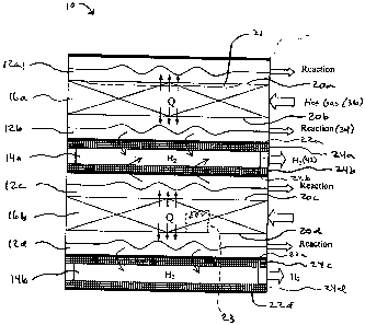
[0016] A schematic view of a portion of an embodiment of the reactor of the
invention is
indicated in general at 10 in Fig. 1. As illustrated in Fig. 1, the reactor
features a number of
reaction channels 12a-12d. While four reaction channels are illustrated in
Fig. 1, the reactor may
have more or may have a lesser number of reaction channels or even one
reaction channel. Each
reaction channel is bounded on one side by a hydrogen channel, 14a and 14b,
and on the other
side by a combustion or heating stream channel, 16a and 16b. Each reaction
channel and heating
stream channel are separated by a heat transfer sheet 20a-20d, preferably
constructed of metal,
upon which a dehydrogenation catalyst, such as nickel, platinum, ruthenium,
rhodium, copper or
other noble metal or alloys thereof, is coated on the reaction side. Each
reaction channel and
hydrogen channel are separated by a membrane containing palladium, vanadium or
a polymer
22a-22d mounted on a porous support plate 24a-24d on the reaction side.
3
CA 02648589 2008-10-07
WO 2007/117702
PCT/US2007/008885
[0017] The heating stream channel may provide heat to the reaction channel by
heat transfer
from a hot gas stream flowing through the heating stream channel.
Alternatively, as will be
explained in greater detail below, combustion catalysts may be optionally
packed or coated in the
heating stream channel, as illustrated at 21 in Fig. 1 for heating stream
channel 16a, so that a
combustion reaction occurs in the heating stream channel. The heat produced by
the combustion
reaction heats the reaction. channel. A third option is to heat a fluid
flowing through the heating =
stream channel by placing an auxiliary electric heating arrangement in the
heating stream
channel, such as the resistance element illustrated in phantom at 23 in Fig. 1
for heating stream
channel 16b.
[0018] A reaction stream passes through each reaction channel where the coated
catalysts are =
used. The reaction stream inlet portion for the reactor consist of a mixture
of supercritical water
and a hydrocarbon fuel. The critical point for water is a temperature of 374 C
at a pressure of
221 bars, which is therefore the minimum temperature and pressure for the
reaction stream inlet
portion.. On the other side of each reaction channel the membrane, supported
by the porous
material, is applied to extract hydrogen from the reaction stream. The
hydrogen generated in
each reaction channel permeates through the membrane and then is collected in
one of the
hydrogen channels at the other side of the membrane. Membranes containing
palladium or
vanadium have a unique property of exclusively allowing hydrogen to permeate
through their
' structures while other gases have molecules that are too large to pass
through the membrane.
High purity hydrogen can be collected on the other side of the membrane while
the other gases
are recycled or collected separately after the reaction from the outlet of the
reaction channels.
[0019] As illustrated in Fig. 1, a heating stream, which may include steam,
inert gas or liquid,
flows through each heating stream channel and provides heat (Q) to the
reaction channels for the
supercritical process. If a combustion catalyst is coated, packed or otherwise
present in the
heating stream channel, a mixture of air or oxygen mixed with a hydrocarbon
may serve as the
heating stream inlet so that combustion occurs. in the heating stream channel
and provides the
heat Q to the reaction channels.
=
[0020] A simplified illustration of a portion of the exterior of the reactor
10 of Fig. 1 without
pipes, headers or manifolds is illustrated in Fig. 2. The reactor features a
housing 30 which
=
4
CA 02648589 2013-10-29
=
contains the heating stream channel 16a, reaction channel 12b and hydrogen
channel 14a (in
addition to the other channels of the reactor, including those illustrated in
Fig. 1). While the
heating stream, hydrogen and reaction channels are illustrated schematically
in Fig. 1 as running
in parallel for ease of explanation, the heating stream and hydrogen channels
may run
perpendicular to, or at any other angle with respect to, the reactionchannels.
In the embodiment
of Fig. 2, the supercritical inlet and outlet portions of the reaction stream
are indicated at 32 and
34, respectively (see also Fig. 1 for 34). The inlet and outlet portions of
the heating stream are
indicated at 36 and 38, respectively (see also Fig. 1 for 36). The hydrogen
outlet stream is
indicated at 42 in both Figs. 1 and 2.
100211 For the situation where combustion catalysts are present in the heating
stream channels of
the reactor 30, the reaction stream outlet 34 may serve as the heating stream
inlet 36, since the
reaction stream outlet contains a residual hydrocarbon, or outlet stream after
fuel cells contains
=
residual hydrogen.
100221 Suitable reactors for use as the reactor of Figs. 1 and 2 are known in
the art. An example
of such a reactor is Chart Industries, Inc.'s SHIMTEC reactor, which is
described in U.S.
Patent Nos. 6,510,894 and 6,695,044.
This compact heat exchange reactor has the capability to perform at the high
temperature and
high pressure required for a process using supercritical water. Moreover, it
provides abundant
surface = area for heat exchange in order to control reaction temperature for
increasing the
hydrogen production and also abundant membrane surface area for greater
hydrogen production
in a small device.
[00231 While the embodiment of Figs. 1 and 2 feature a catalyst that is a.
coating or an
unsupported catalyst, the catalyst can be installed in various alternative
forms such as a packed
bed catalyst having either a supported or an unsupported catalyst, a wash
coated catalyst or
incipient wetness impregnated catalyst producing a thin film on one or more
walls of the reaction
chamber or an electroless plated catalyst. The catalyst can be from a range of
metals including,
but not limited to nickel, platinum, ruthenium, rhodium, copper or alloys
thereof. The catalyst is
used to break the carbon-carbon bonds and carbon-hydrogen bonds in
the'reaction stream:
=
CA 02648589 2008-10-07
WO 2007/117702 PCT/US2007/008885
[0024] While Figs. 1 and 2 illustrate a compact reactor within which hydrogen
may be removed.
from the reaction stream, the removal of hydrogen from the reaction stream may
alternatively be
accomplished outside of the reactor. The process of separating hydrogen from a
stream outside
of a reactor is well known and devices are commercially available. For
example, as illustrated in
Fig. 3, the reaction and separation might be- done in two separate devices 52
and 54 connected by
a passageway, such as a tube, pipe or conduit to simplify the reactor
construction. In such an
arrangement, the first device 52 may be a compact reactor, such as the one
illustrated in, and
described with reference to, Figs. 1 and 2, but without the membranes 22a-22d
and porous plates
24a-24d (Fig. 1) and the hydrogen channels. The reactor 52 is used in a
supercritical condition
for hydrogen generation while the separator device 54 is used for hydrogen
separation from the
product stream 56 exiting the first reactor through the passageway connecting
the reactor and
separator. As with the embodiment of Figs.. 1 and 2, the reaction stream input
portion 58 and
heating stream channel for the reactor 52 may have temperatures above 374 C
and pressures
above 221 bars.
[0025] The conditions for the separator 54 depend on the membrane and support
materials
within the device. For example, if the separator 54 features channels divided
by porous metal
coated with palladium, as illustrated at 22a-22d and 24a-24d of Fig. 1,
operating temperature
could be below 374 C, and operating pressure could be below 221 bars for
hydrogen separation.
The hydrogen stream exiting the separator 54 is illustrated at 62 in Fig. 3,
while the residual
stream (which corresponds to the reaction stream outlet portion 34 in Fig. 2)
is illustrated at 64.
[0026] In an alternative embodiment of the invention, a process swing
adsorption (PSA) process
may be used by the separator 54 instead of a membrane to separate hydrogen
from the product
stream 56. The construction of PSA devices is well known in the art. The PSA
device 54
separates the hydrogen from the product stream gas 56 under pressure according
to the
hydrogen's molecular characteristics and affinity for an adsorbent material.
The device cycles
are to first adsorp hydrogen on the adsorptive material at high *pressure and
then desorp the
hydrogen by lowering the pressure. Hydrogen collection occurs during the low
pressure cycle.
Using two adsorbent vessels allows near-continuous production of hydrogen. It
also permits
pressure equalization, where the gas leaving the vessel being depressurized is
used to partially
6
CA 02648589 2008-10-07
WO 2007/117702 PCT/US2007/008885
pressurize the second vessel. This results in significant energy savings and
is a common
industrial practice. =
[00271 As with the embodiment of Figs. 1 and 2, for the situation where
combustion catalysts are -
present in the heating stream channels of the reactor 52, the residual stream
64 may serve as the
heating stream inlet 60, since the residual stream contains a hydrocarbon (as
well as residual
=
hydrogen).
[0028] As an alternative to the compact reactor 52 of Fig. 3, a tube or
channel reactor 70 could
be used, as illustrated in Fig. 4. The tube reactor 70 is placed in a housing
72 that defines an
interior chamber. The tube reactor serves as the reaction channel and
therefore features a
catalyst coating on its interior surfaces or is packed with a catalyst and
receives a reaction stream
inlet 74. The chamber of housing 72 receives a heating stream 76 whereby heat
is provided to
the reaction channel in the tube reactor 70. As with the embodiment of Fig. 3,
the product
stream 78 from the reactor flows through a passageway, such as a tube, pipe or
conduit to the
separator 82. As with the embodiment of Fig. 3, a hydrogen stream exits the
separator 82, as
illustrated at 84, while the residual stream (which corresponds to the
reaction stream outlet
portion 34 in Fig. 2) exits the separator as illustrated at 86. As with the
embodiment of Fig. 3,
the separator 82 may used either a membrane for the hydrogen separation or a
PSA process.
[0029] Similar to the embodiments of Figs. 1-3, for the situation where
combustion catalysts are
present within the chamber of housing 72, the residual stream 86 may serve as
the heating stream
inlet 76, since the residual stream contains hydrocarbons (as well as residual
hydrogen). Under
such conditions, combustion occurs in the chamber of housing 72 to provide
heat for the reaction
channel of the tube reactor 70.
[0030] In all of the embodiments of the invention described above, hydrogen
production can be
increased by changing the operating conditions of the reactor. For example,
increasing the inlet
pressure of the reaction stream will increase the driving force for the
hydrogen separation. As a
result, reactors which are capable of sustaining higher pressures, such as the
compact reactors .of
the embodiments of Figs. 1-3, will favor more hydrogen production. =
7
CA 02648589 2008-10-07
WO 2007/117702 PCT/US2007/008885
[0031] It should be noted that an equilibrium shift occurs in the reaction
stream. favoring
hydrogen production. More specifically, as the hydrogen concentration
decreases in the reaction
stream, the reaction shifts to produce more hydrogen. Also, the removal of the
reaction product
hydrogen lowers the necessary reaction temperature which increases the range
of materials
acceptable for the reactor. This results in lower cost, better performance and
increased ease of
manufacture for the reactor.
[0032] The embodiments of Figs. 1-4 offer a number of unique benefits
including the generation
of high purity hydrogen efficiently and simply and the generation of a
potentially valuable
byproduct of high pressure CO2 (present in the reaction stream outlet portion
34 of Fig. 2 or
product streams 64 and 86 of Figs. 3 and 4, respectively). In addition to use
as the heating
stream for the reactor, the high pressure CO2 produced may be used for power
plant or
petrochemical complex applications.
[0033] The reaction stream inlet portions for the reactors of Figs. 1-4
consist of a mixture of
supercritical water and a hydrocarbon fuel. As mentioned previously, the
critical point for water
is a temperature of 374 C at a pressure of 221 bars. Water at these conditions
or at a higher
temperature and/or a greater pressure (supercritical water) has. desirable
properties including a
change in the capacity to dissolve liquid hydrocarbons. The hydrocarbon fuel
may be any
hydrocarbon-based fuel such as crude oil, liquid fuels such as jet fuel,
diesel and gasoline,
natural gas, liquid natural gas, coal, coal dust, saw dust, waste wood and/or
biomass material.
Other short chain (e.g. <C6) hydrocarbons may also be used in the reaction
stream with the
water. The temperature can be from 374 C and up and the pressure from 221 bars
and up for
both the reaction and heating streams.
[0034] The supercritical water has the unique feature of high solubility for
most organic liquids,
powders or gases. Hydrocarbon fuels, not ordinarily soluble in water, become
highly soluble in
supercritical Water thus permitting the possibility of a reaction between the
fuel and water on a
catalytic metal based surface, such as nickel, platinum, ruthenium, rhodium,
copper or alloys
thereof. Reaction conversion reaches 100% and the hydrogen yield can exceed
90%, implying
the ability to control the selectivity of the reaction. Details can be seen in
the following
examples.
=
8
CA 02648589 2008-10-07
WO 2007/117702 PCT/US2007/008885
[0035] Two of the most significant benefits from this supercritical process
are that additional
hydrogen (for exaMple, more than 60%) comes from water when using fossil fuel
as a feed, and
CO2 production can be cut significantly (for example, in half) with same
amount of hydrogen
production compared to current fossil fuel combustion systems.
[0036] Examples of the process in embodiments of the invention using different
fuel sources are
described below.
[0037] 1. Toluene
Toluene as a model liquid hydrocarbon feedstock may be used for the
supercritical process. The
desired reaction between toluene and water is as follows:
C6H5CH3 + 14H20 <=> 7CO2+ 18H2
The theoretical yield for this reaction is 39 grams of hydrogen per 100 grams
of toluene, or 18
moles of hydrogen per mole of toluene.
[0038] Ruthenium on alumina (5 wt.% loading, 100 m2/g-cat surface area) may be
used as the
catalyst in one embodiment of the reactor. Such a catalyst may be obtained in
unreduced form
from commercial suppliers. The reaction channels of the reactor are each
packed with Ru/A1203
catalyst. Two-micron fits are placed at each end .of each reaction channel,
thus allowing
reactants to freely pass through while the catalyst is retained.
[0039] Results from testing the reforming of toluene in supercritical water
via Ru/A1203 indicate
that residence times on the order of seconds produce a good yield of hydrogen.
For example, in
a test using a catalytic test reactor consisting of a 1/4 in. OD Incone141)
tube packed with the
catalyst, a 1.9 second reaction time gave a gas mixture of 65.5% H2, 0.9% CO,
5.3% CH4, and
28.3% CO2, with a hydrogen yield of 13.2 and a complete conversion of toluene
to gaseous
products.
[0040] Experiments were carried out at different temperatures ranging from 700
to 800 C using
a feed of 2 .wt.% gasoline and 98 wt.% water. The test reactor pressure was
kept constant at
3500 psi and the residence time in the catalyst was kept at 2 seconds for all
the experiments.
9
CA 02648589 2008-10-07
WO 2007/117702 PCT/US2007/008885
Effect of temperature is shown in Fig. 5, which shows moles of hydrogen yield
per mole of -
toluene for varying residence time, with Ru/AL203 catalyst, 800 C, 3500 psi,
2.1 wt.% toluene
in water, based on calculated equivalent toluene from carbon outlet from the
system.
[0041] The shorter residence time gives better hydrogen yield suggesting that
the reactions are
kinetically controlled. The reaction gives a very good yield of hydrogen; it
is not too far from
the theoretical yield of 18 Moles hydrogen per mole of toluene. Further
adjustment of the
reaction conditions and moving to a compact reactor may improve the yield.
[0042] 2.. Octane
Octane as a model liquid hydrocarbon feedstock may be used for the
supercritical process. The
desired reaction between toluene and water is as follows:
=
C81118 + 16H20 <=> 8CO2+ 25H2
The theoretical yield of this reaction is 26.3 grams of hydrogen per 100 grams
of octane, or 25
moles of hydrogen per mole of octane.
[0043] The same catalyst Ru/A1203 was used for the reaction in the same test
reactor described
above for toluene. The experiment was conducted at 750 C and 3500 psi. The
results are shown
in Table 1.
=
Table 1. Result when using octane
Octane Composition (mol%)
Concentration
wt.% H2 CO CR4 CO2 1-12 yield
2 70.1 1.1 6.1 22.7 18.6
4 63.8 1.6 10.4 24.1 14.4
[0044] The results indicate that hydrogen can be effectively produced in the
supercritical
process. The yield reached 70% with complete octane conversion and further
adjustment of the
CA 02648589 2008-10-07
WO 2007/117702 PCT/US2007/008885
reaction conditions and moving to a compact reactor may =improve the yield.
Increasing the
octane concentration in the feed stream reduces the hydrogen yield.
=
[0045] 3. Model Gasoline
Gasoline is a mixture of several hydrocarbons comprising paraffins, iso-
paraffins, naphthenes
(cyclo-paraffin), and aromatic hydrocarbons with traces of sulfur compounds.
The presence of
sulfur might affect the performance of the catalyst and reduce the hydrogen
yield. Hence for the
comparative analysis, a sulfur-free gasoline was made by mixing iso-octane,
methyl cyclohexane
and toluene in the composition shown in Table 2'.
Table 2. Composition of "sulfur-free"
gasoline
Component Weight percent Mole percent
Iso-octane 50% 45.4%
Methyl cyclohexane 20% 20.6%
Toluene 30% 34.0%
[0046] All of the above compounds are generally present in gasoline and
represent isoparaffin,
naphthene and aromatic hydrocarbons.
[0047] The desired reaction between these hydrocarbons and water during
supercritical
reforming is as follows:
Calls +16H20 8CO2 + 25 H2
C6H11CH3 14H20 <=> 7CO2 21H2
C6H5CH3 14H20 <=> 7CO2 18H2
Overall reaction:
= C7.451113,8 14.91-120 a 7.45CO2+ 21.8
H2
11
CA 02648589 2008-10-07
WO 2007/117702 PCT/US2007/008885
[0048] Hence, each mole of gasoline theoretically can give approximately 21.8
moles of
hydrogen. Or 100 grams of gasoline can theoretically produce 43.6 grams of
hydrogen. The
same catalyst Ru/A1203 was used for the reaction in the same test reactor
described above for
toluene.
[0049] A carbon input/output balance of mare than 95 percent was obtained for
all Of the above
runs. Besides CO2, a small amount of carbon comes out as CO and CH4, as shown
in Fig. 6,
which shows the effect of temperature on gaseous product yields, for 2 wt.%
gasOline in the feed,
reactor pressure of 3500 psi, and 2 second residence time in the Ru/AL203
catalyst bed. A
hydrogen yield of 17 to 19 moles/mole-gasoline was obtained, which suggests
near complete
conversion of carbon to carbon dioxide. The hydrogen yield increased slightly
as the
temperature was increased from 700 to 800 C. The details of gaseous product
distribution and
carbon balance are shown in Table 3.
Table 3. Composition of gaseous product from supercritical water reforming
of gasoline at
3500 psi, 2 second reaction time in Ru/A1203 catalyst bed
Gas Composition Gas Yield
(mole%) (moles of product/mole of hydrocarbon
fed)
( C) H2 CO CH4 CO2 H2 CO. CH4 CO2
800 72.1 0.9 3.1 23.8 18.76 0.24 0.81 6.20
750 71.7 0.7 3.4 24.2 18.51 0.17 0.88 6.25
700 69.7 0.5 5.2 24.7 17.02 0.11 1.27 6.03
=
[0050] Further adjustment of the reaction conditions and moving to a compact
reactor may
improve the yield. =
[0051] A system for producing hydrogen in accordance with the present
invention is illustrated
in Fig. 7. In the system of Fig. 7, hydrogen separation from the reactor
product stream is
accomplished outside of the reactor. Liquid hydrocarbon fuel 111 and water 121
are fed into
=
12
CA 02648589 2008-10-07
WO 2007/117702 PCT/US2007/008885
pumps 110 and 120, respectively, to increase the pressure of each from
approximately 1 bar to
240 bars. Suitable pumps are known in the art and are available, for example,
from Agilent
Technologies, Inc. of Santa Clara, California and Milton Roy of Ivyland,
Pennsylvania. Another
water stream from water recycle stream 516 is fed into a pump 130 to increase,
the pressure to
240 bars and then mixed with fresh water in a mixer 210 to form the stream
212. Both fuel 112
and water 212 streams pass through a heat exchanger 310 to increase the
temperature of each to
approximately 600-800 C via heat exchange with reactor product stream 412.
Stream 312,
supercritical water after the heat exchanger, is mixed with fuel stream 314 in
mixer 220 to form a
reaction stream 222 input for reactor 410.
[00521 The product stream 412 exiting the reactor 410 is directed to. the heat
exchanger 310
where it heats incoming fuel and water streams 112 and 212, respectively, and
then is directed
into a hydrogen separator 510. Hydrogen as a product is collected from 510 and
is distributed
there from, as indicated at 512, for use in fuel cells or hydrogenation. The
rest of the stream 514
goes to a gas separator 520 via a pressure release process. All of the product
gas except
hydrogen is collected in the stream 522 leaving separator 520. A stream of
water 516 exits
separator 520 and is recycled back to mixer 210 to mix with fresh water via
pump 130.
[00531 In the flow diagram, energy is imported to the system via streams 113,
123 and 133 to
power pumps 110, 120 and 130 and stream 411 to provide the heating stream for
reactor 410 (as
'described with reference to Figs. 1-4 for combustion in the heating stream
channels) through
burning residual hydrogen from a fuel cell or hydrocarbon from the gas
separator 520.
=
[00541 In addition, a process for fuel desulphurization may optionally be
included in the
hydrogen generation process of the invention. The purpose of such a process is
to remove sulfur
compounds which can poison the catalyst in the reactor 410. A supercritical
process provides a
means of desulphurizing the fuel source as sulfur compounds may be separated
due to unique
properties achievable under supercritical conditions. More specifically,
sulfur inorganic
compounds normally are dissolved in water solution, but will form deposits in
supercritical
condition. In addition, some sulfur organic compounds form suspension in
supercritical water
condition. Either of these behaviors leads to the possibility of mechanically
separating the sulfur
from the fuel through the process of forming sulfur compounds which may be
physically
13
CA 02648589 2013-10-29
=
separated in the separator device, illustrated in phantom at 600 in Fig. 7.
The separator device
600 may be, for example, a molecular sieve featuring a zeolite structure. The
separator device
600 adsorbs the sulfur contamination as the fuel/reaction stream (222 in Fig.
7) flows through the
device. The usual practice is to place two sieves in parallel and alternate
between the process
flow and regeneration. One sieve, 600 in Fig. 7, is regenerated by desorption
while the process
, flow goes through the other sieve 602.
[00551 The supercritical process and reactor described above work well over a
wide range of
conditions and with various hydrocarbon fuel sources having a wide range of
purities. In
addition, the ratio of hydrogen fuel produced to the amount of CO2 generated
is much higher than
if hydrocarbon fuel were burned by itself and the energy cost to operate the
reactor and system is
low for the amount of energy produced. The residence time for the reaction
process is shortened
due to the large heat exchange and separation surface areas provided in the
reactor, which also
facilitate the separation of hydrogen in the reactor.
[00561 While embodiments of the invention have been shown. and described, it
will be apparent
to those skilled in the art that changes and modifications may be made therein
without departing
from the scope of the invention as outlined in the appended claims.
=
14