Note: Descriptions are shown in the official language in which they were submitted.
CA 02648933 2008-10-09
WO 2007/121480 PCT/US2007/066893
APPARATUS AND METHOD FOR COOLING LIQUID IN INTRAVASCULAR
COOLING SYSTEM
CROSS-REFERENCE TO RELATED APPLICATIONS
This application claims priority to U.S. Patent Provisional Application Serial
No. 60/793,164 filed April 18, 2006, entitled "APPARATUS AND METHOD FOR
COOLING LIQUID IN INTRAVASCULAR COOLING SYSTEM". The foregoing
patent application is incorporated herein by reference in its entirely.
FIELD OF THE INVENTION
The present invention relates to a portable apparatus and related method
for rapid vascular cooling of a patient. The invention is particularly apt for
treating
stroke, head trauma and cardiac arrest patients in an ambulatory vehicle.
BACKGROUND OF THE INVENTION
The therapeutic use of rapid bodily cooling systems is ever-increasing. Of
particular interest, it is now accepted that rapid cooling of stroke, cardiac
arrest
and head trauma patients can yield significant therapeutic benefits.
Specifically,
research indicates that even though a stroke or cardiac arrest victim's brain
cells
may loose their ability to function, the cells do not necessarily die quickly.
In fact,
brain damage from a stroke or cardiac arrest may take hours to reach maximum
effect. Neurological damage may be reduced and the stroke or cardiac arrest
victims' outcome improved if a neuroprotectant therapy is applied within this
time
frame.
Similarly, elements in the genesis of a traumatic brain injury (e.g.,
resulting
from falls, vehicular accidents and the like) are now understood to overlap
with
elements in the genesis of neurological damage in stroke victims. In
particular,
delayed secondary injury at the cellular level after the initial head trauma
is now
recognized as a major contributing factor to the ultimate tissue loss that
occurs
after brain injury. Again, neurologic damage may be reduced if a
neuroprotectant
therapy is rapidly applied. Further, in this regard, studies have shown that
treatment with mild hypothermia, defined as lowering core body temperature at
2-
3C confers neuroprotection in stroke victims, and may hasten the neurologic
recovery and improve outcomes when applied for 12-72 hours in cases of
-1-
CA 02648933 2008-10-09
WO 2007/121480 PCT/US2007/066893
traumatic head injury. Again, to optimize such therapies, the neuro-protective
therapy should be initiated as soon as possible after a stroke or traumatic
head
injury.
As these and other medical applications for rapid bodily cooling have
continued to evolve, the present inventors have recognized the desirability of
enhancing the portability, stowability and ease-of-use of patient cooling
systems
so that patient treatment may be promptly initiated. More particularly, while
known patient cooling systems have proven effective for many applications, the
present inventors have recognized that additional emergency-oriented
applications can be realized via the implementation of further improved liquid
cooling methodologies and stand-alone componentry, as well as enhanced
componentry packaging. In this regard, the present inventors have recognized
the need for a cooling system and related methodology that is particularly apt
for
use in ambulatory settings, including, in particular, use in emergency
vehicles
such as helicopters, ambulances and the like where space utilization is at a
premium and patient access may be limited.
SUMMARY OF THE INVENTION
In view of the foregoing, a primary objective of the present invention is to
provide a portable patient cooling system that reduces space storage and
patient-
site space requirements, is lightweight and yields highly effective patient
cooling.
A further objective of the present invention is to provide an apparatus and
method for patient cooling that is easy to set-up and is otherwise user-
friendly.
Another objective of the present invention is to provide an on-demand
patient cooling system that reduces or avoids the need for electrical or other
on-
board power utilities.
Another objective of the present invention is to provide an improved
patient cooling apparatus and related method that is cost effective.
Yet another objective of the present invention is to provide an apparatus
and method for patient cooling that is, at least in part, adapted for single
patient
use and ready disposal.
One or more of the above objectives and additional advantages may be
realized in the present invention which includes a portable apparatus and
associated method for providing a cooled liquid for vascular administration.
The
-2-
CA 02648933 2008-10-09
WO 2007/121480 PCT/US2007/066893
portable apparatus may include a source of liquid for vascular administration
(e.g., one or more bags containing about 1 liter to 4 liters and preferably
1.5 liters
to 3 liters of a saline solution, plasma solution, etc.), and a cooling
reservoir for
receiving liquid from the source. Additionally, the portable apparatus may
include
a sorption-based heat exchanger for cooling liquid in the cooling reservoir,
wherein the sorption-based heat exchanger may include an evaporative area for
receiving and vaporizing a refrigerant therein, a sorptive material for
sorping
vaporized refrigerant (e.g., a desiccant), and a heat exchange member for
conducting thermal energy from the liquid in the cooling reservoir into the
evaporative area, wherein the liquid received in the cooling reservoir may be
rapidly cooled.
As will be appreciated, the employment of a sorption-based heat
exchanger not only yields rapid cooling of a liquid for vascular
administration, but
also facilitates the realization of numerous additional benefits, including
enhanced portability, stowability and on-demand liquid cooling. Further, the
employment of a sorption-based heat exchanger avoids the need for electrical
or
other power requirements for liquid cooling.
In relation to cooling capabilities, the inventive apparatus may cool liquid
at
a rate sufficient to lower a patient's core temperature by .5 C to 4 C, and
preferably 1 C to 2 C, over a cooled liquid infusion period of 15 minutes to
60
minutes, and preferably 20 minutes to 30 minutes. Characterized another way,
the inventive apparatus may yield a total energy transfer of 7 kcal to 104
kcal and
preferably 19.5 kcal to 60 kcal.
In another aspect, the cooling reservoir of the inventive apparatus may
comprise an inlet for receiving liquid from the source and an outlet for
passing
liquid out of the cooling reservoir, and at least one flow channel for flowing
the
liquid between the inlet and outlet. Such an arrangement facilitates the
overlapping flow of liquid into and out of the cooling reservoir, e.g., as
opposed to
a sequential flow protocol. In this regard, when a liquid is flowed into the
cooling
reservoir inlet at a temperature of 15 C to 30 C, and preferably 20 C to 25 C,
such liquid may be sufficiently cooled to an outlet temperature of 2 C to 8 C,
and
preferably 5 C to 7 C, thereby yielding a liquid temperature drop of 7 C to 26
,
and preferably 13 C to 20 C, within the cooling reservoir.
-3-
CA 02648933 2008-10-09
WO 2007/121480 PCT/US2007/066893
The inlet may be located at a location on the cooling reservoir that is
disposed below the outlet during use (e.g., an inlet at a bottom end and an
outlet
near a top end), so as to facilitate the removal of any gaseous bubbles in the
cooled liquid (e.g., removal by an optional gas removal device discussed
below). Preferably, a plurality of flow channels may extend between the inlet
and
outlet of the cooling reservoir, so as to equalize thermal transfer between
the
heat exchange member and cooling reservoir (e.g., by reducing low flow regions
in the cooling reservoir). In this regard, at least a portion of each of the
plurality
of flow channels may be disposed to extend adjacent to the heat exchange
member of the sorption-based heat exchanger for thermal conduction
therebetween. More specifically, at least a portion of each of the flow
channels
may extend substantially parallel to a corresponding surface portion of the
heat
exchange member. In one arrangement, one or more of the flow channels may
be disposed to define a non-linear path between the inlet and outlet of the
cooling
reservoir, thereby increasing the degree of achievable cooling for liquid
passing
therethrough.
In another aspect, the cooling reservoir may be provided so as to define a
sterile internal volume for receiving and transferring liquid from the source.
In this
regard, the apparatus may be provided to include a sterile first liquid flow
line
(e.g., flexible tubing) fluidly interconnected or fluidly interconnectable
between the
source and the cooling reservoir, and a sterile second liquid flow line (e.g.,
flexible tubing) fluidly interconnected or fluidly interconnectable between
the
reservoir and a vascular interface device (e.g., vascular catheter). Further,
the
apparatus may include an enclosure for containing, in a sterile, enclosed
area, at
least the cooling reservoir, the first liquid flow line and the second liquid
flow line
prior to use. Such an arrangement facilitates shipping, stowability and ready
set-
up/use. Further, such an approach allows sterile packaging to be reliably
completed at a production location.
Optionally, additional liquid flow componentry may be advantageously
provided or otherwise employed together with the cooling reservoir and first
and
second liquid flow lines. In particular, at least one flow control member may
be
provided to allow for control over the initiation/termination and rate of
liquid flow
into and out of the cooling reservoir. For example, a flow control member may
be
provided for contact engagement with the first liquid flow line (e.g.,
-4-
CA 02648933 2008-10-09
WO 2007/121480 PCT/US2007/066893
interconnected for selective occlusive engagement therewith) or second liquid
flow line. Alternatively, a flow control member may be provided for flow
control
use either upstream and/or downstream of the first and/or second liquid flow
lines. Further, a gas removal device may be provided to remove gaseous
bubbles from liquid flowing to a patient. For example, a gas removal device
may
be disposed along the first or second liquid flow line (e.g., fluidly
interconnected
in-line therewith) or downstream thereof. Additionally, a source
interconnection
member (e.g., a bag spike with a removable cover) may be provided at one end
of the first liquid flow line for ready connection to the vascular cooling
liquid
source, and a vascular interconnection member may be provided (e.g., a luer
connector with a removable cap, a spikeable tubing length or a twist-off
spikeable
port) may be provided at one end of the second liquid flow line for ready
interconnection to a vascular access device (e.g., having a vascular catheter
fluidly interconnected or interconnected to a patient at one end and a
compatible
luer connector at another end). As may be appreciated, any/all of such flow
componentry may be packaged in a sterile condition separately, or together
with
the noted cooling reservoir and liquid flow lines to further facilitate
storage and
ready use.
In yet a further aspect, the apparatus may include a flow pump device for
pumping liquid from the vascular liquid source and into/out of the cooling
reservoir. More particularly, the flow pump device may be operable to maintain
a
predetermined flow rate, e.g., preferably between about 50 ml./min. and 100
ml./min. In preferred arrangements, the flow pump device may be of a
mechanical nature so as to avoid the need for electrical or other power
sources.
For example, a manually inflatable bladder device (e.g., inflatable via a hand-
operated, valved pump) may be utilized to apply a compressive force against a
flexible vascular liquid source so as to displace liquid from the source at a
predetermined rate.
In one arrangement, the cooling reservoir may be provided so as to be
removably positionable adjacent to the heat exchange member of the sorption-
based heat exchanger. For example, the cooling reservoir may be configured
(e.g., a laminar configuration) for convenient slide-in/slide-out placement in
a
coincidentally-configured receiving slot (e.g., vertically oriented) provided
on the
sorption-based heat exchanger. Such an approach facilitates reuse of the
-5-
CA 02648933 2008-10-09
WO 2007/121480 PCT/US2007/066893
sorption-based heat exchanger and ready removal/separate disposal of the
cooling reservoir after use. In another approach, the reservoir may be fixedly
positioned adjacent to the heat exchange member of the sorption-based heat
exchanger. Such approach further facilitates initial set up procedures, and
yields
an arrangement in which the cooling reservoir and sorption-based heat
exchanger may be packaged/stowed together and disposed of together after use.
In yet a further aspect, the cooling reservoir may be provided to be either
removably positionable or fixedly positioned in direct contact with a first
side of
the heat exchange member of the sorption-based heat exchanger, wherein the
evaporative area and sorptive material are located on an opposing second side
of
the heat exchange member of the sorption-based heat exchanger. In turn, the
evaporative area and sorptive material may be located within an enclosed
volume
of the sorption-based heat exchanger. In conjunction with this aspect, the
portable apparatus may further include a vessel containing a refrigerant
(e.g., a
liquid refrigerant comprising water), and an actuator selectively actuatable
to
fluidly interconnect and thereby flow the refrigerant from the vessel into the
enclosed volume. The enclosed volume of the sorption-based heat exchanger
may be maintained at internal pressure that is less than an internal pressure
of
the vessel prior to fluid interconnection. In this regard, the enclosed volume
may
be maintained at a predetermined subatmospheric pressure prior to and after
activation. By way of example, the predetermined subatmospheric pressure may
be less than about 5 hectopascals (hPa) and most preferably less than about 2
hPa.
In one arrangement, the vessel and actuator may be provided as part of
the sorption-based heat exchanger. In other arrangements, the vessel and
actuator may be separately disposed with a fluid interconnection to the
sorption-
based heat exchanger. In one embodiment, the actuator may comprise a
depressible member for puncturing the refrigerant vessel so as to allow liquid
refrigerant to flow into the evaporative area. that is, for example, a user
may
simply push in on one end of the depressible member thereby causing another
end thereof to breach a refrigerant vessel that is contained within another
vessel
fluidly interconnected to the evaporative area. The inclusion of a selectively
actuatable actuator for the sorption-based heat exchanger further facilitates
the
provision of an on-demand, portable cooling solution.
-6-
CA 02648933 2008-10-09
WO 2007/121480 PCT/US2007/066893
In one arrangement, the refrigerant vessel may be partially defined by a
flexible surface that is disposed for exposure to atmospheric pressure,
wherein
upon the selective actuation of the actuator, a flow path is defined between
the
vessel and the enclosed volume of the sorption-based heat exchanger that is
maintained at subatmospheric pressure. The pressure differential facilitates
the
flow of liquid from the refrigerant vessel into the evaporative area. As may
be
appreciated, such an arrangement further facilitates the automatic passage of
refrigerant from the vessel into the evaporative area.
In further relation to this aspect, the sorption-based heat exchanger may
include a vapor permeable membrane, which is disposed between the heat
exchange member/evaporative area and sorptive material within the enclosed
volume (e.g., disposed parallel to the heat exchange member to define the
evaporative area therebetween). In this regard, the vapor permeable membrane
functions to restrict the passage of refrigerant in the evaporative area to
that
which has been vaporized, e.g., as opposed to refrigerant in a liquid form.
The heat exchange member may comprise any material that allows for
thermal energy conduction between liquid in the cooling reservoir and the
evaporative area. In one approach, the heat exchange member may comprise a
metal (e.g., an aluminum plate), thereby facilitating thermal energy transfer
and
also yielding structural integrity.
In some embodiments at least one distribution member may be provided
with the vapor permeable membrane to facilitate distribution of refrigerant
flowing
into the evaporative area. In one approach, a porous wicking member may be
positioned between a front side of the heat exchange member and a backside of
the vapor permeable member. By way of example, the porous wicking member
may extend for at least a majority of the length of the vapor permeable
membrane and may have a portion that is positioned adjacent to an inlet
through
which liquid refrigerant passes from the vessel into the evaporative area. In
another approach, a vapor impermeable member may be positioned adjacent to
a front side of the vapor permeable membrane. For example, the vapor
impermeable membrane may extend for at least a majority of the length of the
vapor permeable membrane and may have a portion that is positioned adjacent
to an inlet through which liquid refrigerant passes from the vessel into the
-7-
CA 02648933 2008-10-09
WO 2007/121480 PCT/US2007/066893
evaporative area. The distribution members described above may be employed
separately or in tandem.
Additionally, the sorption-based heat exchanger may comprise at least one
spacer member extending through the sorptive material to define at least one
corresponding channel region for receiving vaporized refrigerant therethrough.
More preferably, a plurality of spacer members are provided so as to provide
for
enhanced contact between vaporized refrigerant and sorptive material. In turn,
such increased contact yields increased/efficient liquid cooling capabilities,
thereby facilitating rapid patient cooling.
Relatedly, the sorption-based heat exchanger may be provided to include
a phase change material (e.g., a hydrated salt or paraffin-based material) for
extracting thermal energy attendant to sorption of the vaporized refrigerant
by the
sorptive material. In this regard, it is preferable that at least a portion of
the
phase change material be located directly adjacent to at least a portion of
the
sorptive material. By way of example, a plurality of spacer members may be
disposed transversely (e.g., perpendicular) to the evaporative area, with
sorptive
material adjacent to each side of each spacer member and phase change
material disposed therebetween (e.g., to yield a multi-layered, laminar
arrangement).
In one arrangement, the sorption-based heat exchanger may also include
a porous insulation layer disposed between the vapor permeable membrane and
the sorptive material (e.g., disposed in parallel relation to the heat
exchange
member and vapor permeable member).
As noted, the present invention also provides an inventive method for
supplying a cooled liquid for vascular administration. The inventive method
may
include the steps of flowing a liquid for vascular administration from a
source into
a cooling reservoir, conducting thermal energy from the liquid in the cooling
reservoir into an evaporative area of a sorption-based heat exchanger, and
passing cooled liquid from the cooling reservoir to a vascular interface
device. As
may be appreciated, the conduction of thermal energy may be realized via
vaporization of a refrigerant within the evaporative area, wherein the
vaporized
refrigerant is sorped by a sorptive material within the sorption-based heat
exchanger.
-s-
CA 02648933 2008-10-09
WO 2007/121480 PCT/US2007/066893
In one aspect of the inventive method, the conduction of thermal energy
may act to cool liquid within the cooling reservoir between about 7 C and 26
C,
and preferably between about 13 C and 20 C, relative to a starting temperature
of the liquid within a source (e.g., a saline solution having a temperature of
between about 15 C and 30 C and preferably 20 C to 25 C, in a bag). In a
related aspect, upon passing the cooled liquid from the cooling reservoir to a
vascular interface device, the cooled liquid may be administered to a patient,
wherein the cooled liquid acts to cool the patient between about .5 C and 4 C,
and preferably between about 1 C and 2 C (e.g., over a period of about 15
minutes to 60 minutes, preferably 20 minutes to 30 minutes). Characterized in
another way, in conducting thermal energy from the liquid, a total transfer of
between about 7 kcal and 104 kcal of thermal energy may be realized, and
preferably between about 14.5 kcal and 60 kcal.
In a further related aspect, the evaporative area of the sorption-based heat
exchanger may be located within the enclosed volume. In turn, the inventive
method may provide for restricting the passage of refrigerant in a liquid form
from
the evaporative area, i.e., so as to permit substantially only vaporized
refrigerant
to contact the sorptive material. By way of primary example, such restriction
may
be achieved by locating a vapor permeable membrane between the evaporative
area and the sorptive material.
In an additional aspect, the conduction of thermal energy into the
evaporative area may be initiated by selectively introducing the refrigerant
in a
liquid form into the evaporative area. More particularly, such selective
introduction may entail flowing of the liquid refrigerant from a vessel into
the
evaporative area by selectively fluidly interconnecting the vessel and
evaporative
areas, e.g. by manual depression of an actuator and/or by utilizing
atmospheric
pressure acting upon a flexible side of the vessel. Further in this regard,
the
enclosed volume of the sorption-based heat exchange may be maintained at an
internal pressure less than an internal pressure of the liquid refrigerant
vessel,
wherein upon actuating an actuator, liquid refrigerant may flow from the
vessel
into and vaporize within the evaporative area. In one approach, the enclosed
volume may be maintained at a subatmospheric pressure of less than about 5
hectopascal (hPa), and preferably less than about 2 hPa prior to and after
actuation.
-9-
CA 02648933 2008-10-09
WO 2007/121480 PCT/US2007/066893
In another aspect, sorption of the vaporized refrigerant by the sorptive
material may be carried out by contacting the vaporized refrigerant with the
sorptive material within the enclosed volume of the sorption-based heat
exchanger (e.g., to condense the vapor on the sorptive material). In a related
aspect, thermal energy released by the sorptive material upon sorption of the
vaporized refrigerant may be extracted within the enclosed volume by a phase-
change material. By way of example, the extracting step may comprise
extracting thermal energy generated by the sorption material during sorption
by
utilizing a phase-change material having a solid to liquid transition
temperature of
from about 10 C to 80 C.
In yet a further aspect, the method may comprise the steps of
interconnecting the source for liquid administration to the cooling reservoir
via a
first flow line prior to the flowing step, and connecting the cooling
reservoir to a
vascular interface device prior to the flowing step. Further, the flowing step
may
entail pumping the liquid through the first liquid flow line of the cooling
reservoir
and second liquid flow line. By way of example, and as noted above, such
pumping may be achieved by utilization of a manual pumping device, e.g., an
inflatable bladder device that is hand-operated (e.g. by squeezing a flexible,
valved chamber to inflate the bladder device) .
In a related aspect, interconnection of the vascular liquid source to the
cooling reservoir may be accomplished by manually connecting an
interconnection member provided at one end of the first liquid flow line to
the
source, wherein a second end of the first liquid flow line is one of
interconnected
and adapted for interconnection to the reservoir. Similarly, fluid
interconnection
of the reservoir to a vascular interface device may entail a manual connection
of
an interconnection member at one end of the second liquid flow line to a
vascular
interface device (e.g., a vascular catheter), wherein a second end of the
second
liquid flow line is one of interconnected and adapted for interconnection to
said
reservoir.
In a further aspect, the method may include the step of controlling a flow
control device to control the flow of liquid from the source through the
cooling
reservoir. More particularly, the controlling step may provide for
initiating/stopping the flow of liquid and/or otherwise controlling the rate
of flow of
liquid through the first liquid flow line and/or second liquid flow line. In
one
-10-
CA 02648933 2008-10-09
WO 2007/121480 PCT/US2007/066893
arrangement, the controlling step may include manual adjustment of a flow
control device that engages a first liquid flow line or a second liquid flow
line so
as to control a degree of occlusion of the first liquid flow line to effect
the rate of
liquid flow therethrough. In another arrangement, a flow control device may be
utilized downstream of a second liquid flow line.
In an additional aspect, the method may further comprise the step of
removing gas from liquid flowing through the first liquid flow line and/or the
second liquid flow line. By way of example, such removing step may accomplish
by passing the liquid in the second liquid flow line through a vented drip
chamber
disposed along and fluidly interconnected with the second liquid flow line
(e.g.,
having a hydrophobic membrane to permit the passage of gas and restrict the
passage of liquid therethrough).
In addition to the foregoing aspects, the method may further include the
step of packaging the reservoir, first liquid flow line and second liquid flow
line in
a sterile enclosure. Further, such packaging step may provide for inclusion of
a
first interconnection member interconnected or interconnectable to one end of
a
first liquid flow line, a second interconnection interconnected or
interconnectable
to one end of the second liquid flow line, a flow control device as noted
above
and/or a gas removal device as noted above in the sterile enclosure. Further,
in
arrangements where the reservoir is fixedly interconnected with a sorption-
based
heat exchanger, the packaging step may provide for the further inclusion of
the
sorption-based heat exchanger within the sterile envelope.
In conjunction with this aspect, the packaging step may be efficiently
completed at a production location. In this regard, the various componentry
may
be sterilized before packaging or collectively sterilized after packaging.
Relatedly, then the method may entail the additional step of unpackaging the
various components packaged in the sterile enclosure at a patient care site
remote from the production site. By way of example, such patient care site may
be within an ambulatory vehicle.
In conjunction with the above-noted aspect relating to the various
componentry interconnections, the method may further provide for disconnection
of the second connection member from the vascular interface device, and single-
step disposal of interconnected ones of the second interconnection member,
-11-
CA 02648933 2011-11-09
second liquid flow line, cooling reservoir, first interconnection member and
source
in a joint fashion.
According to another aspect, there is provided a portable apparatus for
selective, on-demand bodily cooling of a patient by providing a cooled liquid
for
administration into a vascular system of a patient, comprising:
a portable source of a liquid for vascular administration;
a portable cooling reservoir for receiving liquid from said source, including:
an inlet that is one of interconnected and interconnectable to the
portable source for receiving said liquid therefrom;
an outlet that is one of interconnected and interconnectable to a
vascular interface device;
a portable sorption-based heat exchanger for cooling said liquid received
in said portable cooling reservoir from said portable source, including:
a vessel containing refrigerant;
an evaporative area for receiving and vaporizing said refrigerant
therein;
a sorptive material for sorping vaporized refrigerant; and,
a heat exchange member for conducting thermal energy from said
liquid received in said portable cooling reservoir into said evaporative
area; and,
an actuator selectively actuable by a user to flow said refrigerant
from said vessel into said evaporative area to provide selective cooling of
said liquid received in said portable cooling reservoir for vascular
administration to a patient.
According to a further aspect, there is provided a method for providing a
cooled liquid for vascular administration, comprising:
flowing a liquid for vascular administration from a source into a cooling
reservoir;
conducting thermal energy from said liquid in said cooling reservoir into an
evaporative area of a sorption-based heat exchanger by vaporizing a
refrigerant
within said evaporative area, wherein said vaporized refrigerant is sorped by
a
sorptive material within said sorption-based heat exchanger; and
-12-
CA 02648933 2011-11-09
passing cooled liquid from said cooling reservoir to a vascular interface
device.
Additional aspects and advantages of the present invention will become
apparent to those skilled in the art upon consideration of the Detailed
Description
and claims that follow.
BRIEF DESCRIPTION OF THE DRAWINGS
FIG. 1 illustrates one embodiment of an inventive portable apparatus for
providing a cooled liquid for vascular administration.
FIG. 2A illustrates a front perspective view of one embodiment of a
sorption-based heat exchanger and adjacently-disposed cooling reservoir
comprising the present invention.
FIG. 2B illustrates a rear view of the cooling reservoir of the embodiment
of FIG. 2A.
FIG. 2C illustrates a front perspective view of the embodiment of FIG. 2A,
with a portion of a housing member cut away to show internally-disposed
componentry.
FIG. 2D illustrates a top cross-sectional view of the embodiment of FIG.
2A taken along the cut plane 2D-2D.
FIG. 3A illustrates a back member of the cooling reservoir of the
embodiment of FIG. 2A.
FIG. 3B illustrates the back member and a front member of the cooling
reservoir of the embodiment of FIG. 2A.
FIG. 4 illustrates one embodiment of an inventive method for providing a
cooled liquid for vascular administration.
FIG. 5 illustrates an exploded assembly view of another embodiment of a
sorption-based heat exchanger and adjacently-disposed cooling reservoir
comprising the present invention.
FIG. 6A, 6B and 6C illustrate a front view, back view and side view of a
back member of a cooling reservoir of the embodiment of FIG. 5.
FIG. 7 illustrates a perspective cross-sectional view of the embodiment of
FIG. 5, with a housing member removed and a portion of an outer pouch of a
liquid refrigerant cooling reservoir cut away.
-12a-
CA 02648933 2008-10-09
WO 2007/121480 PCT/US2007/066893
FIG. 8 illustrates a perspective rear view of a cooling reservoir of the
embodiment of FIG. 5.
DETAILED DESCRIPTION OF THE INVENTION
FIG. 1 illustrates one embodiment of a portable apparatus 10 for cooling a
liquid for vascular administration. As shown, the portable apparatus 10 may
include at least one source reservoir(s) 20 containing a liquid appropriate
for
cooling a patient via vascular administration. By way of example, the source
reservoir(s) 20 may contain a predetermined volume of a saline solution,
plasma
solution, or other solution, e.g., preferably about 1 liter to 4 liters of a
saline
solution, and more between about 1.5 liters to 3 liters of a saline solution.
As
may be appreciated, bags of saline solution are frequently otherwise kept
within
ambulatory vehicles for vascular administration and may be conveniently
utilized.
The portable apparatus 10 may further include a cooling reservoir 30 for
receiving liquid from source reservoir(s) 20 and a sorption-based heat
exchanger
50 for cooling liquid received in the cooling reservoir 30. In one approach,
the
cooling reservoir 30 may be removably positionable relative to the sorption-
based
heat exchanger 50 for conductive thermal transfer therebetween (e.g., in a
slot
configured for mattingly receiving the cooling reservoir 30), wherein the
cooling
reservoir 30 is separately disposable to facilitate reuse of the sorption-
based heat
exchanger 50. In another approach, the cooling reservoir 30 may be fixedly
positioned relative to the sorption-based heat exchanger 50 for conductive
thermal transfer therebetween, wherein the cooling reservoir 30 and the
sorption-
based heat exchanger 50 may be conveniently packaged and disposed of as a
unit, and wherein set-up procedures may be expedited.
In either approach, it is preferable to define an arrangement in which a
predetermined amount of total energy is transferable between sorption-based
heat exchanger 50 and liquid from source reservoir(s) 20 flowing into and out
of
cooling reservoir 30, e.g., between about 20 kcal and 80 kcal, and more
preferably between about 30 kcal and 60 kcal. Relatedly, it may be preferable
to
provide a portable apparatus 10 capable of cooling liquid from source
reservoir(s)
20 so as to lower a patient's core temperature by .5 C to 4 C, and preferably
1 C
to 2 C, during vascular cooling (e.g., over a period of about 15 to 60 minutes
and
preferably 20 minutes to 30 minutes).
-13-
CA 02648933 2008-10-09
WO 2007/121480 PCT/US2007/066893
Various additional flow componentry may be interconnected and/or readily
interconnectable "upstream" between the source reservoir(s) 20 and cooling
reservoir 30, and "downstream" of the cooling reservoir 30. For example, the
upstream and downstream components may include a first liquid flow line 60 and
a second liquid flow line 70 (e.g., flexible tubing lines having a bore size
of
between about .8 mm and 3 mm), respectively, each interconnected or
interconnectable to cooling reservoir 30. More particularly, in the
illustrated
embodiment, the first liquid flow line 60 may be fluidly interconnected or
interconnectable at a first end to an inlet port 32 of the cooling reservoir
30.
Further, the first liquid flow line 60 may selectively be interconnectable at
a
second end to the source reservoir(s) 20. In the latter regard, at least one
interconnection member 62 may be provided at the second end of the first
liquid
flow line 60 for selective fluid interconnection to the source reservoir(s)
20. By
way of example, the interconnection member 62 may be bag spike having a
vented cap as shown, or may otherwise be defined by a lure connector or any
other type of connector adapted for ready fluid interconnection with source
reservoir(s) 20.
In the illustrated embodiment, a first flow control member 64 may be
included along the length of the first liquid flow line 60 for controlling the
flow of
liquid through the first liquid flow line 60 to cooling reservoir 30. By way
of
example, first flow control member 64 may be a roller clamp that depressibly
engages, and thereby occludes, a flexible first liquid flow line 60 to control
the
rate of liquid flow therethrough. Additionally, a second liquid flow control
member
66 may be disposed along the length of the first liquid flow line 60 to
control the
flow of liquid therethrough. For example, the second liquid flow control
member
66 may take the form of a slide clamp having a central opening with a v-shaped
portion for progressively receiving and thereby occluding a flexible first
liquid flow
line 60 therein.
In addition to the noted flow components, a flow pump device 68 may be
provided for pumping liquid from the source reservoir(s) 20. That is, the flow
pump device 68 may be provided to flow liquid from the source reservoir(s) 20
and into and out of the cooling reservoir 30 at a predetermined rate, e.g.,
between about 20 ml./min. to 200 ml./min., and more preferable between about
50 ml./min. and 100 ml./min. Relatedly, it may be preferable to provide flow
-14-
CA 02648933 2008-10-09
WO 2007/121480 PCT/US2007/066893
pump device 68 and cooling reservoir 30 so that the liquid pressure drop from
first liquid flow line 60 to second liquid flow line 70 is less than about 80
mmHg.
and more preferably less than about 30 mmHg.
While automated pumping devices may be utilized, FIG. 1 illustrates an
embodiment in which the flow pump device 68 is defined by an inflatable
bladder
that is readily positionable around or otherwise in contact with at least a
portion of
a flexible cooling reservoir 30 to apply a compressive force thereto when
inflated.
By way of example, an inflatable bladder of the type marketed by Ethox Corp.,
of
Buffalo, New York, U.S., under the trade name INFU-SURG may be utilized.
Such device comprises a valved, hand-squeezable pump for drawing in ambient
air and dispensing the air into an inflatable bladder. As may be appreciated,
the
utilization of an inflatable bladder to provide a motive force for flowing
liquid from
the source reservoir(s) 20 reduces on-board power requirements and otherwise
yields space efficiencies, stowability benefits, and reduced costs.
At this point, it should be noted that FIG. 1 illustrates the utilization of
plural source reservoir(s) 20 so as to increase the total volume of liquid
available
for vascular administration to a patient. Specifically, two source
reservoir(s) 20
are provided (e.g., each containing 11. of saline solution), and concomitantly
a
first liquid flow line 60 is provided with first and second spur lines 60a and
60b
that are fluidly interconnected via a Y-connector 69. Correspondingly, each of
the spur lines 60a, 60b are provided with a corresponding second flow control
member 66 and interconnection member 62 (e.g., bag spikes). Further, separate
flow pump devices 68 may be utilized in relation to each of the source
reservoir(s) 20.
As further shown in FIG. 1, a first end of the second flow line 70 may be
fluidly interconnected to an outlet port 34 of the cooling reservoir 30 and a
second
end of the second liquid flow line 70 may be fluidly interconnectable to an
intravascular access device 90. Such intravascular access device 90 may
comprise a vascular catheter fluidly interconnected to a female luer 92. In
this
regard, an interconnection member 72 may be provided at the second end of the
second liquid flow line 70 for selective fluid interconnection to the vascular
access
device 90. By way of example, the interconnection member 72 may take the
form of a male luer that is initially provided with a removable cap to
maintain
sterility.
-15-
CA 02648933 2008-10-09
WO 2007/121480 PCT/US2007/066893
In an illustrated embodiment, a gas removal device 74 may be included
along the length of the second liquid flow line 70 for removing gas from the
liquid
flowing through the second liquid flow line 70 from reservoir 30. By way of
example, the gas removal device 74 may be a vented drip chamber. Additionally,
a medication administration port member 76 may be disposed along the second
liquid flow line 70 to allow for the selective introduction of a medication
into the
second liquid flow line 70.
As may be appreciated, the various flow components interconnected
and/or interconnectable to the first liquid flow line 60 and second liquid
flow line
70 may be sterilized and packaged together with cooling reservoir 30. Such
consolidated packaging facilitates sterilization procedures, transport and
storage
in emergency patient transport vehicles, and otherwise facilitates rapid set-
up
procedures. In this regard, such componentry may be readily removed from the
sterile packaging, interconnected to source reservoir(s) 20 and an
intravascular
access device 90 for patient cooling.
In a simplified arrangement, a portable apparatus may simply comprise a
sorption-based heat exchanger 50, a cooling reservoir 30, and a first liquid
flow
line 60 and a second liquid flow line 70 interconnectable to an inlet port 32
and
outlet port 34, respectively, of the cooling reservoir 30. An interconnection
member 62 (e.g., bag spike) may be provided at one free end of the first
liquid
flow line 60 and another interconnection member 72 (e.g., a spikeable tubing
section) may be provided at one end of the second liquid flow line 70 for
selective
fluid interconnection with a separately provided intravascular tubing set. In
the
latter regard, the interconnectable intravascular tubing set may include a
compatible interconnection member (for example, a spike) at one end, a gas
removal device (e.g., a vented bubble trap), a flow control member (e.g., a
roller
clamp), and an optional drug introduction member interconnected along the
length of a tubing line and a luer connector at a free end for selective
interconnection to an intravascular access device. Of note, the various above-
noted components of the portable apparatus can be packaged together in one
sterile enclosure and the components of the interconnected intravascular
tubing
set may be packaged together in another sterile enclosure.
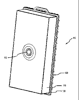
Referring now to FIGS. 2A-2D, one embodiment of a sorption-based heat
exchanger 100 will be described. As shown in FIG. 2A, the sorption-based heat
-16-
CA 02648933 2008-10-09
WO 2007/121480 PCT/US2007/066893
exchanger 100 includes a housing member 110 interconnected to a front side of
a heat exchange member 120 to define an enclosed volume therebetween. For
example, a peripheral edge of housing member 110 may be fixedly sealed (e.g.,
via a light-activated adhesive) to a peripheral rim portion of the front side
of heat
exchange member 120. In this embodiment, a cooling reservoir 130 is fixedly
interconnected to an opposing, backside of the heat exchange member 120. For
example, a peripheral edge of cooling reservoir 130 may be fixedly sealed
(e.g.,
via a light-activated adhesive) to a peripheral rim portion of the back side
of heat
exchange member 120.
Upon selective actuation of an actuator 112 the sorption-based heat
exchanger 100 provides for the selective vaporization of a liquid refrigerant
within
the enclosed volume on the first side of the heat exchange member 120, wherein
thermal energy is conducted from liquid received within the cooling reservoir
130
from a source reservoir(s) 20 to cool the liquid. To yield high conduction
cooling
and otherwise provide structural rigidity the heat exchange member 120 may
comprise a metallic material, e.g., aluminum, having a thickness of about .25
mm
to 2 mm and preferably about .5 mm to 1 mm. In the latter regard, and as shown
in FIG. 2B, the cooling reservoir 130 includes a bottom inlet port 132 and top
outlet port 134 fluidly interconnectable or otherwise interconnected to first
and
second liquid flow lines 60 and 70, respectively, wherein liquid flows through
the
reservoir 130 from bottom to top to facilitate gas removal by a downstream or
upstream gas removal device. In another arrangement, the location of ports 132
and 134 may be reversed, wherein liquid flows through the reservoir 130 from
top
to bottom.
Referring now to FIG. 2C, the sorption-based heat exchanger 100 is
illustrated with a portion of the housing member 110 cut away to show
components disposed within the enclosed volume thereof. As illustrated, such
componentry is arranged in a front-to-back layered manner. In particular, the
sorption-based heat exchanger 100 includes a liquid refrigerant vessel 140, a
sorption layer 150, a thermal insulation layer 160, and a vapor permeable
membrane 170 adjacently disposed in a laminar fashion on the front side of the
heat exchange member 120.
The liquid refrigerant vessel 140 may interface with the actuator 112 of
housing member 110 so that, upon selective depression of the actuator 112 by a
-17-
CA 02648933 2008-10-09
WO 2007/121480 PCT/US2007/066893
user, a flow path is defined from the liquid refrigerant vessel 140 into an
evaporative area located between a back side of the vapor permeable membrane
170 and front side of the heat exchange member 120. More particularly, the
liquid refrigerant vessel 140 may comprise an inner pouch containing a liquid
refrigerant and an outer pouch having top and bottom flow bands 142 that have
open passageways therethrough with open port ends that are fluidly
interconnected with the noted evaporative area through corresponding openings
in vapor permeable membrane 170.
In the latter regard, vapor permeable membrane 170 may be provided to
have a vaporized liquid refrigerant transmission rate of between about
4800g/m2/day and 290,000 g/m2/day, and more preferably between about 21,000
g/m2/day and 111,000 g/m2/day. In this regard, vapor permeable membrane 170
may be preferably define a surface area for vaporized liquid refrigerant
transmission of between about 400 cm2 and 1,200 cm2, and preferably between
about 300 cm2 and 800 cm2. The vapor permeable membrane 170 may be
defined by a microporous material including, for example, one or materials
selected from a group consisting of:
Polyethylene;
Polyurethane;
Polypropylene; and,
Polytetrafluoroethylene (PTFE).
Examples of suitable vapor permeable membrane materials include
various porous films such as TYVEK polyethylene films (E.I. duPont deNemours
Corporation, Wilmington, Del.), GORE-TEX films (W. L. Gore and Associates,
Newark, Del.), hydrophilic dense polyurethane films and porous hydrophobic
polyurethane films such as those supplied by Porvair (Porvair pic., Norfolk,
United Kingdom). The membrane can also have a hydrophilic coating such as
SCOTCH-Guard (3M Company).
Upon depression of the actuator 112 the inner pouch is punctured so that
liquid refrigerant flows from the inner pouch into the outer pouch and through
the
flow bands 142 into the evaporative area. In this regard, the enclosed volume
of
the sorption-based heat exchanger 100 may be maintained at a subatmospheric
pressure, e.g., less than about 5 hectopascal (hPa) or 5 millibar (mbar), and
more
preferably less than about 2 hPa or 2 mbar. Further, at least a front surface
114
-18-
CA 02648933 2008-10-09
WO 2007/121480 PCT/US2007/066893
of the housing member 110 and an adjacent front surface 144 of the liquid
refrigerant vessel 140 may both be of a flexible construction. In turn, upon
actuation of the actuator 112, atmospheric pressure acting upon the front
surface
114 of the housing member 110, and in turn upon the front surface 144 of the
liquid refrigerant vessel 140, will facilitate the flow of liquid refrigerant
through the
flow bands 142 and into the evaporative area which is at a subatmospheric
pressure.
By way of example, the liquid refrigerant contained in vessel 140 may
comprise one or more liquids selected from a group consisting of ammonia,
various alcohols such as methyl alcohol or ethyl alcohol, ketones (e.g.,
acetone)
or aldehydes (e.g., acetaldehyde). Other useful liquids can include
chlorofluorocarbons (CFC) or hydrochlorofluorocarbons (HCFC) such as FREON
(E.I. Dupont de Nemours, Wilmington, Del.), a series of fluorocarbon products
such as FREON C318, FREON 114, FREON 21, FREON 11, FREON 114B2,
FREON 113 and FREON 112. Other useful fluorocarbons liquids include HCFC-
134a, HCFC-141 b and HCFC-245fa. Preferably, the liquid includes water, and in
one embodiment the liquid consists essentially of water. Water is advantageous
due to its high heat of vaporization, low cost and low toxicity. However, it
may be
desirable to include minor amounts of other components in the liquid in order
to
control the evaporative properties of the liquid. For example, the liquid can
be
mixed with a component having a low vapor pressure or with a gas, such as
carbon dioxide. In one embodiment, water may be provided in vessel 140 with a
volume of between about 50 ml. and 150 ml., and preferably between about 90
ml. and 110 ml.
Reference is now made to FIG. 2D, which is a top cross-sectional view
taken along cut-plane 2D-2D shown in FIG. 2C. Of note, the cooling reservoir
130 includes a plurality of fluid channels 136 that are each fluidly
interconnected
to inlet port 132 and fluid outlet port 134 (not shown). Such fluid
interconnections
will be further described in reference to FIG. 3A below. The fluid channels
136
extend along and adjacent to the back surface of the heat exchange member 120
to facilitate conductive heat transfer therebetween.
Of further note in FIG. 2D, the sorption layer 150 comprises a plurality of
spacer members 152 each defining a corresponding channel region 153
therethrough for the passage of vaporized liquid refrigerant. As shown, the
-19-
CA 02648933 2008-10-09
WO 2007/121480 PCT/US2007/066893
spacer members 152 extend perpendicularly away from the heat exchange
member 120, vapor permeable membrane 170 and thermal insulation layer 160.
Additionally, between each of the adjacent spacer members 152 a sorptive
material 154 is provided, wherein liquid refrigerant vapor may contact and
thereby be sorped by the sorptive material 154. Concomitantly, to extract
thermal
energy released in conjunction with such sorption, a phase change material 156
may be provided, e.g., adjacent to the sorptive material 154. In this regard,
while
only one spacer member set 152 is illustrated in FIG. 2 with sorptive material
154
and phase change material 156 located therebetween, it will be understood that
the volume between each set of spacer members 152 may be similarly provided
with sorptive material 154 and phase change material 156.
In one embodiment, the spacer members 152 may be defined by a netting
material. More particularly, such netting may be an extruded material (e.g.,
comprising polyethylene or polypropylene) and may be of a woven nature so as
to define corresponding channel regions 153. In turn, each spacer member 152
may define a corresponding channel region 153 having a thickness, or width, of
between about .5 mm and 2 mm for vaporized liquid refrigerant passage
therethrough.
In one embodiment, sorptive material 154 may comprise a desiccant
material. By way of example, the desiccant material may include one or more
materials selected from a group consisting of: zeolite, barium oxide,
activated
alumina, silica gel, glycerine, magnesium perchlorate, calcium sulfate,
calcium
oxide, activated carbon, calcium chloride, glycerine silica gel, alumina gel,
calcium hydride, phosphoric anhydride, phosphoric acid, potassium hydroxide
and sodium sulfate.
In one implementation the desiccant may be a surface modified porous
material. The porous material can be a material such as activated carbon or
silica. The surface modification can include impregnating the porous material
with one or more metal salts such as a metal salt selected from the group
consisting of calcium chloride, lithium chloride, lithium bromide, magnesium
chloride, calcium nitrate, potassium fluoride and the like. The porous support
material may be loaded with from about 20 to about 80 weight percent of the
metal salt and more preferably from about 40 to about 60 weight percent of the
metal salt. In one embodiment, a predetermined amount of sorptive material 154
-20-
CA 02648933 2008-10-09
WO 2007/121480 PCT/US2007/066893
may be employed to achieve a desirable amount of cooling, e.g., between about
66 gm. and 700 gm. of a desiccant, and more preferably between about 90 gm.
and 300 gm. of a desiccant.
By way of example, the phase change material 156 may comprise a
hydrated salt and/or a paraffin material. The phase change material may have a
transition temperature of from about 10 C to about 80 C. More preferably, the
phase-change material may have a transition temperature of at least about 25
C.
It is desirable to utilize phase-change materials that have a transition
temperature
above ambient (e.g., 25 C) to simplify the storage of such materials. As used
herein, transition temperature refers to the temperature at which the phase-
change material undergoes a phase-change, e.g., from a solid to a liquid.
The phase-change material may also be provided to have a high energy
density. The energy density may be measured in terms of mass (mass energy
density) or volume (volumetric energy density). Mass energy density refers to
the
amount of energy that is released or adsorbed by the phase-change material per
unit mass of the phase-change material. Volumetric energy density refers to
the
amount of energy that is released or adsorbed by phase-change material per
unit
volume of the phase-change material. The phase-change material may have a
volumetric energy density of at least about 200 J/cm3, more preferably at
least
about 275 J/cm3 and most preferably at least about 350 J/cm3. Exemplary
phase-change materials include inorganic compounds such as disodium sulfate
decahydrate, disodium hypophosphate dodecahydrate, barium hydroxide
octahydrate, paraffins such as octadecane, and combinations thereof. In order
to
provide a range of transition temperature, it may be desirable to mix two or
more
phase-change materials. In one embodiment, a predetermined amount of phase
change material 156 may be included to achieve a desired amount of cooling,
e.g., between about 600 grams and 1600 grams, and more preferable between
about 800 grams and 1200 grams. In some embodiments, it may be desirable to
restrict mixing of the desiccant and the phase-change material, especially at
or
above the transition temperature of the phase-change material. When the phase-
change material is in a liquid or gas phase, as is the case above its
transition
temperature, it may cause unwanted chemical reactions with the desiccant or
lessen thermal communication with the desiccant by reducing the amount of
phase-change material in contact with the desiccant. In such a case, a fluid
-21-
CA 02648933 2008-10-09
WO 2007/121480 PCT/US2007/066893
diffusion barrier may be employed to prevent the phase-change material from
contacting the desiccant or from changing its shape.
The fluid diffusion barrier can be any type of barrier which prevents the
phase-change material from interspersing with the desiccant. The fluid
diffusion
barrier may also have a high thermal conductivity to enable efficient thermal
communication between the desiccant and phase-change material. Exemplary
fluid diffusion barriers include simple plastic films such as polyethylene,
nylon,
PVC, metal foils with plastic heat seal layers such as those sold by Toyo
Aluminum (Osaka, Japan), metallized plastic barrier such as those sold by
DuPont (Wilmington, Del.) and Rexam (London, England), multilayer plastic
layers and combinations thereof. In addition to preventing fluid diffusion,
the fluid
diffusion barrier may be employed to provide mechanical protection for the
phase-change so that it retains its original shape and is resistant to
physical or
chemical changes in its structure. This may be accomplished by any means
known in the art, including placement of the phase-change material in a heat-
sealed pouch comprising the fluid diffusion barrier.
As noted above, cooling reservoir 130 of the embodiment shown in FIGS.
2A-2B may comprise a plurality of flow channels 136. In this regard, reference
is
now made to FIGS. 3A and 3B which illustrate a back member 180 and a front
member 190 interconnected to the back member 180, respectively. In particular,
and as shown in FIG. 3A, the back member 180 may include a plurality of
vertically oriented ribs 182 extending away from a sheet-like layer 184 to
define
at least a portion of the flow channels 136 therebetween. By way of example,
flow channels 136 may be provided to have a filled thickness (e.g., as
measured
between back member 180 and front member 190) of between about 1 mm and
.4 mm, and preferably between about .15 mm and .25 mm. Further, the flow
channels may be provided to have a length of between about 10 cm and 200 cm,
and preferably between about 15 cm. and 40 cm.
In the latter regard, the internal ends of inlet port 132 and outlet port 134
extend through the layer 184 and are located so that liquid may flow through
inlet
port 132 into an inlet staging area adjacent to the bottom ends of the flow
channels 136, through the flow channels 136, into an outlet staging area
adjacent
to the top ends of flow channels 136, and through outlet port 134. In one
embodiment, a liquid from source reservoir(s) 20 may be passed through cooling
-22-
CA 02648933 2008-10-09
WO 2007/121480 PCT/US2007/066893
reservoir 130 and cooled by sorption-based heat exchanger 100, wherein a
liquid
temperature at inlet port 132 of between about 15 C and 30 C, and preferably
between about 20 C and 25 C is provided, and a liquid temperature at outlet
port
134 of between about 2 C and 8 C, and preferably between about 5 C and 7 C
is realized.
As shown in FIG. 3B, the front member 190 may be interconnected to the
back member 180 about an external rim 186 and along the edges of ribs 182 of
the back member 180. To provide structural support, and as shown in FIGS. 3A,
3B and 2B, the back side of the back member 180 may be provided with a
plurality of transverse reinforcement members 188 (e.g., raised ribs disposed
in a
waffle-like pattern).
Referring now to FIG. 3C, the heat exchange member 120 of the sorption-
based heat exchange 100 is shown in a juxtaposed position relative to a front
side of the front member 190 of cooling reservoir 130. Further, an optional
first
distribution member 174, comprising a porous material, is shown to facilitate
the
distribution of a liquid refrigerant. More particularly, and with reference to
both
FIGS. 3C and 3D, the first distribution member 174 is positioned between the
front side of the heat exchange member 120 and a back side of the vapor
permeable membrane 170. In the latter regard, and as shown in FIG. 3D, the
vapor permeable membrane 170 may be interconnected to a peripheral portion of
the heat exchange number 170 by an open frame member 126. Further, the
vapor permeable membrane 170 may be provided with a top opening 172
therethrough (e.g., located on a center axis thereof) to receive liquid
refrigerant
through the flow band 142 of the liquid refrigerant reservoir 140 (as shown in
Fig.
2C), upon actuation of the actuator 112.
In turn, and referring again to FIG. 3C, the first distribution member 174 is
located so as to have a top end thereof in adjacent relation to the opening
172
through the vapor permeable membrane 170 so that liquid refrigerant may be
received at the top end of the first distribution member 174 for distribution
into the
evaporative area defined between the heat exchange member 120 and vapor
permeable membrane 170. In this regard, the first distribution member 174 may
extend along a center axis of the vapor permeable membrane 170 substantially
the length of the evaporative area. Similarly, while shown in a more narrow
configuration in FIG. 3C, the first distribution member 174 may be of
substantially
-23-
CA 02648933 2008-10-09
WO 2007/121480 PCT/US2007/066893
the same width as the evaporative area to further facilitate distribution of
the
liquid refrigerant. In one arrangement, the first distribution member 174 may
comprise a wicking material, e.g., a non-woven fabric.
Referring now to FIG. 3E, an optional second distribution member 176,
comprising a material that is substantially impermeable to vapor, including
vaporized liquid refrigerant, is illustrated for facilitating the distribution
of liquid
refrigerant within the evaporative area defined between the heat exchange
member 120 and the vapor permeable membrane 170. More particularly, the
second distribution member 176 may be interposed between a front side of vapor
permeable member 170 and a back side of the thermal insulation layer 160. As
shown, the second distribution member 176 may be interconnected to the front
side of the vapor permeable member 170 and may be of an elongated
construction extending along a center axis of the vapor permeable membrane
170. As illustrated, the optional second distribution member 176 may extend
downward from a top end of and around opening 172 of the vapor permeable
membrane 170. By virtue of the vapor impermeability of the second distribution
member 176, the maintenance of a coincidentally-shaped open liquid refrigerant
flow channel on a back side of a vapor permeable member 170 within the
evaporative area may be facilitated. For example, the second distribution
member 176 may yield a relatively warmer coincidental channel within the
evaporative area so as to reduce any tendency for liquid refrigerant freezing
along the coincidental region. In turn, the distribution of liquid refrigerant
through
the coincidental region may be enhanced.
Referring now to FIGS. 3F and 3G, thermal insulating layer 160 and the
sorption layer 150 are shown in their corresponding positions, wherein
respectively, the thermal insulating layer 160 is positioned adjacent to a
front side
of the vapor permeable membrane 170 and the sorption layer 150 is located in
juxtaposed relation to a front side of the thermal insulating layer 160. In
turn,
FIG. 3H illustrates the liquid refrigerant reservoir 140 disposed in
juxtaposed
position on a front side of the sorption layer 150. As may be appreciated, the
flow band 142 of the liquid refrigerant reservoir 140 may be interconnected to
a
front side of the vapor permeable membrane 170 at opening 172 prior to the
placement and interconnection of the optional second distribution member 176,
thermal insulating layer 160 and sorption layer 150. Finally, and as shown in
-24-
CA 02648933 2008-10-09
WO 2007/121480 PCT/US2007/066893
FIG. 31, actuator 112 may be disposed adjacent to a front side of the liquid
refrigerant reservoir 140.
In one example, a portable apparatus 110 may be provided so that, prior
to interconnection with an intravascular access device 90 and source(s) 20,
the
sorption-based heat exchanger 100 and cooling reservoir 130 have a total
weight
of less than about 2.5 kg, and preferably less than about 1.5 kg. Further,
such
embodiment may have overall dimensions of about 10"-12" (height), 4"-6"
(width),
and V-2" (thickness).
Referring now to FIG. 4, one embodiment of a method for providing cooled
liquid for vascular administration will be described. In such description,
various
components of the above-described apparatus embodiments will be referenced
to facilitate a better understanding of the methodology.
In this regard, it is contemplated that the inventive apparatus and method
will provide particular advantages in the context of emergency care for
patients
being transported from a remote site to a patient care facility, such as a
hospital.
More particularly, the inventive apparatus and method are particularly adapted
for
use in an ambulatory vehicle where space constraints and ease-of-use are of
primary importance.
In the event of an emergency procedure 200, as shown in FIG. 4,
emergency personnel may initially remove a cooling reservoir 30, 130 and
associated flow componentry from a sterile enclosure stored within an
emergency
vehicle (step 210). In this regard, such componentry may be packaged in the
enclosure together at a production site, and unpackaged together at the
patient
care site. The associated flow componentry may include first and second liquid
flow lines 60, 70, interconnected or interconnectable to the cooling reservoir
30,
130, as well as optional first and second flow control members 64, 66,
optional
first interconnection member 62 for first flow line 60, optional second
interconnection member 72 for second flow line 70, gas removal member 74 and
optional medication port 76 for second liquid flow line 70. Further, in
arrangements where the cooling reservoir 30, 130 is fixedly interconnected or
otherwise integrated with a sorption-based heat exchanger 50, 100, sorption-
based heat exchanger 50 may also be included in the packaging noted.
In arrangements where the sorption-based heat exchanger 50 is
separately provided, e.g., to facilitate reuse thereof, the cooling reservoir
30 will
-25-
CA 02648933 2008-10-09
WO 2007/121480 PCT/US2007/066893
need to be initially positioned in contact relation to the sorption-based heat
exchanger 30 after unpackaging (step 220). For example, a support slot may be
provided by the sorption-based heat exchanger 50 for removably and slidably
receiving the cooling reservoir 30.
Next, the various flow componentry may be utilized to interconnect the
cooling reservoir 30, 130 to a source of liquid for vascular cooling 20 and to
a
vascular interface device 90 (step 230). For example, and in relation to the
above-described embodiment 10, interconnection member 62 may be
interconnected to a liquid source 20, and interconnection member 72 may be
interconnected to intravascular interface device 90. Concomitantly, a flow
pump
device 68 may be interfaced with the liquid source 20 (step 240). By way of
example, an inflatable bladder may be positioned to engage a flexible liquid
source 20, wherein the inflatable bladder may be manually inflated by a user
(e.g., via a hand-held pumping device) so as to apply a compressive force to
the
liquid source 20. After fluid interconnections have been made with the various
flow componentry, such componentry may be primed with liquid from the liquid
source 20 (step 250). For example, the first and/or second flow control
members
64 and 66 may be moved from a first position in which liquid is restricted
from
flowing from liquid source 20 to a second position in which liquid may flow
from
the liquid source 20, through first flow line 60, cooling reservoir 30, 130
and
second flow line 70.
After priming, vascular interface device 90 may be interconnected to a
vascular aspect of a patient (step 260). By way of example, an IV catheter may
be inserted into a patient's vascular system in a conventional manner.
To initiate patient cooling, adsorption-based heat exchanger 50, 100, may
then be actuated, via depression of actuator 112 of heat exchanger 130, so as
to
cool liquid passing into cooling reservoir 30, 130 (step 270). As previously
discussed, in relation to sorption-based heat exchanger 100, such actuation
will
result in the flow of liquid refrigerant from refrigerant vessel 140 into an
evaporative area of sorption-based heat exchanger 100, whereupon the
refrigerant vaporizes and thermal energy is conducted from the liquid in the
cooling reservoir 30, 130. In turn, the cooled liquid is flowed into the
vascular
system of the patient via the second flow line 60, via interconnection member
72
and vascular interface device 90. As may be appreciated, the flow and cooling
of
-26-
CA 02648933 2008-10-09
WO 2007/121480 PCT/US2007/066893
liquid from source 20 may continue until the patient has been cooled to a
desired
temperature and/or otherwise reaches the hospital or other care facility.
When vascular cooling of the patient is completed, the various flow
components, cooling reservoir 30, 130 and utilized liquid source(s) 20 may be
disposed of. Again, when the sorption-based heat exchanger 30, 130 is fixedly
interconnected or otherwise integrated with a cooling reservoir 30, 130, such
sorption-based heat exchanger 30, 130 may be disposed together with the
above-noted items.
FIGS. 5, 6A-6C, 7 and 8 illustrate another embodiment of a sorption-based
heat exchanger 300 and cooling reservoir 330 that comprise components and are
operable in a manner similar to that of the sorption-based heat exchanger 100
and cooling reservoir 130 described above, respectively. In general, the
cooling
reservoir 330 may be defined by a back member 380 and a front member 390. In
turn, the sorption-based heat exchanger 300 includes, a heat exchange member
320, interconnected to a front side of the cooling reservoir 330, and a
housing
member 310 interconnected to a front side of the heat exchange member 320 to
define an enclosed volume therebetween that may house additional components
of the sorption-based heat exchanger 300 in a layered manner. FIG. 5
illustrates
such additional componentry, wherein "front" and "back" sides of the
components
are facing upwards and downwards, respectively, and wherein top ends and
bottom ends of the components are located on the left and right sides,
respectively.
As shown in FIG. 5, an optional first distribution member 374 may be
located adjacent to a front side of the heat exchange member 320, a vapor
permeable membrane 370 may be located adjacent to a front side of the heat
exchange member 320 and first distribution member 374, an optional second
distribution member 376 may be located adjacent to a front side of the vapor
permeable membrane 370, a thermal insulating layer 360 may be located
adjacent to a front side of the vapor permeable membrane 370 and second
distribution member 376, a sorption layer 350 may be located adjacent to a
front
side of the thermal insulating layer 360 and a liquid refrigerant vessel 340
may be
located adjacent to a front side of the sorption layers 150. The heat exchange
member 320, vapor permeable membrane 370, sorption layer 350 and liquid
refrigerant vessel 340 may be of a construction analogous to the heat exchange
-27-
CA 02648933 2008-10-09
WO 2007/121480 PCT/US2007/066893
member 120, vapor permeable membrane 170, sorption layer 150, and liquid
refrigerant vessel 140, respectively, described above in relation to the
sorption-
based heat exchanger 100.
The first distribution member 374 may comprise a porous wicking material
374b (e.g., a non-woven fabric material) held in position relative to heat
exchange
member 320 by an outer adhesive frame member 374b. In the latter regard, the
frame member 374b may comprise adhesive on both a front side and back side
thereof, wherein the wicking member 374 is held in position between the frame
member 374b and heat exchange member 320, and wherein the vapor
permeable membrane 370 is held in position by and relative to the adhesive
front
surface of the frame member 374b. Optionally, a double-sided adhesive locator
374c may be interconnected to a front side of the wicking member 374a and to a
bottom side of the vapor permeable membrane 370, wherein an opening through
the locator 374c is aligned with an opening 372 through a top end of the vapor
permeable membrane 370. In this regard, in operation liquid refrigerant may
pass from the liquid refrigerant vessel 340 through a flow band 342 thereof
through the opening 372 of the vapor permeable membrane 370, and through the
corresponding opening through the locator 374c, wherein the liquid refrigerant
may then be distributed by the first distribution member 374 within an
evaporative
area defined between the heat exchange member 320 and vapor permeable
membrane 370.
The second distribution member 376 may comprise a vapor impermeable
material having an adhesive surface disposed on at least a back side thereof
for
connection to the vapor permeable membrane 370. In one approach, a pressure-
sensitive acrylic adhesive transfer tape may be employed, wherein a first
adhesive side may be applied to the vapor permeable membrane 370 and a
polycoated kraft liner removed from a second adhesive side thereof (e.g.,
product
reference 468MP offered by 3M Company of St. Paul, Minnesota). The second
distribution member 376 may include an opening disposed in aligned relation
with
the opening 370 of the vapor permeable membrane 370. In turn, the flow band
342 of the liquid refrigerant vessel 340 may be adhesively interconnected to a
top
end of the second distribution member 376, wherein a fluid outlet 342a of the
flow
band 342 is disposed in aligned relation with the openings of the second
distribution member 376, the vapor permeable membrane 370 and the locator
-28-
CA 02648933 2008-10-09
WO 2007/121480 PCT/US2007/066893
374c. The optional second distribution member 376 may be utilized to reduce
any tending for freezing on a back side of the vapor permeable membrane 370,
thereby facilitating the distribution of liquid refrigerant that flows into
the
evaporative area between a front side of the heat exchange member 320 and a
back side of the vapor permeable membrane 370 during use.
As shown in FIG. 5, the thermal insulating layer 360 may be defined by a
porous insulation member 362 disposed within a porous, outer envelope 364. By
way of example, the insulating member 362 may be defined by a plurality of
netting material layers (e.g., comprising extruded polyethylene or
polypropylene),
while the envelope 364 may be defined by a non-woven fabric material (e.g., a
40
gram per square meter, spunbonded polypropylene fabric) having relatively non-
abrasive outer surfaces to reduce undesired interference between the
insulating
layer 360 and the vapor permeable membrane 370 as well as other interfacing
components.
In the latter regard and as shown in FIG. 5, the sorption layer 350 may be
located adjacent to a front surface of the envelope 364 of the insulating
layer 360
and adjacent to a back surface of the liquid refrigerant vessel 340, wherein
the
flow band 342 of the liquid refrigerant vessel 340 may wrap around a top end
of
the sorption layer 350. With particular reference to the sorption layer 350, a
plurality of sets of spacer members 352, sorption material layers 354 and
phase-
change material layers 356 may be arranged in a stack, or bundle 357, wherein
the bundle 357 may be held in compressive, interfaced engagement via an outer
porous retaining member 359 (e.g., a fabric material wrapped tightly about and
heat-sealed along edges to maintain compression of the stack 357). By way of
example, a single set is shown in Fig. 5, wherein each set may include a pair
of
spacer members 352, with an adjacent pair of sorption material layers 354 and
a
single layer of a phase-change material 356 located therebetween in a
laminated
fashion.
With further reference to FIG. 5, the liquid refrigerant vessel 340 may
comprise an outer sealed pouch 346 of flexible construction and an inner
sealed
pouch 348 disposed within the outer pouch 346. The inner pouch 348 may
comprise a predetermined volume of liquid refrigerant (e.g., a water-based
refrigerant as described above) which may be selectively passed from within
the
inner pouch 348 into the outer pouch 346 for passage via flow band 342 into
the
-29-
CA 02648933 2008-10-09
WO 2007/121480 PCT/US2007/066893
evaporative area defined between the vapor permeable membrane 370 and heat
exchange member 320 described hereinabove. The inner pouch 348 may be
fluid-tight and restrict the passage of vapor and gas therethrough. For
example,
the inner pouch 348 may be of a multilaminate construction including a first
vessel that comprises a fluid diffusion barrier material (e.g., a metal foil),
and a
second vessel comprising a reinforcement material (e.g., a polymer-based
material). In one arrangement, two reinforcement layers are utilized, one
comprising polyethylene and another comprising polyester).
As shown, an actuator 312 may be provided for selectively penetrating the
inner pouch 348 of the liquid refrigerant vessel 340 to permit passage of the
liquid
refrigerant from the inner pouch 348. In this regard, the actuator 312 may
include
a dome member 312a and an underlying actuator tack 312b both positioned
inside and adjacent to the front of the outer pouch 346 and outside and
adjacent
to the front of the inner pouch 348 of the liquid refrigerant vessel 340.
Further, a
support member 312c and an underlying anvil member 312d, corresponding in
shape with the dome member 312a, may be located inside and adjacent to the
back of the outer pouch 346 and outside and adjacent to the back of the inner
pouch 346.
As illustrated, a top layer of the outer pouch 346 of the liquid refrigerant
reservoir 340 and a top layer of the outer housing 310 may be configured in a
coincidental configuration relative to the dome member 312d to facilitate
positioning and operation of the actuator 312.
The outer housing 310, may be fluid-tight and restrict the passage of vapor
and gas therethrough. For example, the outer housing 310 may be of a
multilaminate construction including a first vessel that comprises a fluid
diffusion
barrier material (e.g., a metal foil), and a second vessel comprising a
reinforcement material (e.g., a polymer-based material). In one arrangement,
two
reinforcement layers are utilized, one comprising polyethylene and another
comprising polyester.
Referring now to FIGS. 6A, 6B and 6C, the back member 380 of cooling
reservoir 330 will be further described. As shown in FIG. 6A, the back member
380 may include an inlet port 332 and outlet port 334 through which liquid may
be
passed for cooling within the cooling reservoir 330 and provided to a patient
for
vascular administration as described hereinabove. More particularly, an inlet
-30-
CA 02648933 2008-10-09
WO 2007/121480 PCT/US2007/066893
channel 336a may be located adjacent to the inlet port 332 for distributing
liquid
from the inlet port 332 to a bottom end of the cooling reservoir, illustrated
at the
left side of FIGS. 6A, 6B and 6C. In turn, the outwardly extending lateral
channels 336b adjoin the distribution channel 336a, wherein liquid may pass
through the lateral channels 336b. Further, interconnected longitudinal
channels
336c may be provided along a center axis and the outside periphery of the back
member 380. As illustrated, lateral channels 336b may be interconnected to the
longitudinal channels 336c along the length of the back member 380 to
facilitate
the flow of liquid through the cooling reservoir 330 to outlet port 334. The
various
channels described above may be defined above by raised ribs 382 and
peripheral ribs 386.
As shown in FIGS. 6B and 6C, the inlet port 332 and outlet port 334 of the
back member 380 may be provided with interconnected L-shaped, or elbow
members 333 and 335, respectively, to facilitate interconnections and routing
of
liquid flow lines as well as compact packaging. By way of example, the L-
shaped
members 333, 335 may be integrally formed with the back member 380 (e.g.
molded polyethylene).
Reference is now made to FIG. 7 which illustrates a cross-sectional view
of the sorption-based heat exchanger 300 with the outer housing 310 removed
for purposes of illustration. As shown, the actuator dome 312a is configured
to
define a cup-shaped, middle dome portion and an inverted U-shaped annular
portion thereabout. Such a configuration facilitates plastic deformation of
the
actuator dome 312a upon the application of force upon the middle dome portion,
wherein the actuator dome 312a may be plastically deformed from a first set
position, shown in FIG. 7, to a second set position in which the actuator tack
312b has penetrated the inner pouch 348. In this regard, actuator tack 312b
may
be located on a center axis of the middle dome portion of the dome member
312a, wherein upon the application of force to the middle dome portion (e.g.,
manually by a user's finger) the dome member 312a will plastically deform
inward
forcing the actuator tack 312b inward so as to penetrate through the inner
pouch
348 of the liquid refrigerant vessel 340. The actuator tack 312b may penetrate
through both sides of the inner pouch 348 and be stopped from penetration of
outer pouch 346 upon contacting the anvil 312d. The support member 312c may
comprise an extruded netting material (e.g., a .01" thick disc of polyester)
so as to
-31-
CA 02648933 2008-10-09
WO 2007/121480 PCT/US2007/066893
support the inner pouch 348 and allow the actuator tack 312b to penetrate
completely through both sides of the inner pouch 348. Upon penetration of the
inner pouch 348, liquid refrigerant contained within the inner pouch 348 may
pass
into the outer pouch 346, through the flow band 342 and into the evaporative
area defined between the heat exchanger 320 and vapor permeable membrane
310, wherein vaporization and attendant cooling may occur.
Reference is now made to FIG. 8 which shows the back surface of the
back member 380 of the cooling reservoir 330. More particularly, FIG. 8
illustrates various flow componentry that may be interconnected to and
packaged
together with the cooling reservoir 330. In particular, a first liquid flow
line 60
(e.g., a flexible tubing line) may be fluidly interconnected at a first end to
the inlet
port 332 via L-shaped member 333. Further, the first liquid flow line 60 may
selectively be interconnectable at a second end to a source reservoir(s) 20
(as
shown in Fig. 1) containing a liquid appropriate for cooling a patient via
vascular
administration. In this regard, at least one interconnection member 62 (e.g.,
a
bag spike with a vented cap) may be provided at the second end of the first
liquid
flow line 60. Additionally, a first control member 64 may be included for
controlling the flow of liquid through the first liquid flow line 60. By way
of
example, the flow control member 64 may comprise a V-shaped clamp member
that depressively engages, and thereby occludes, a portion of a flexible first
liquid
flow line 60.
With further reference to FIG. 8, a second liquid flow line 70 (e.g., a
flexible tubing line) may be interconnected to the outlet port 334 of the
sorption-
based heat exchanger 330 via L-shaped member 335. In turn, a second end of
the second liquid flow line 70 may be fluidly interconnectable to an
intravascular
device 90 as previously described. In this regard, an interconnection member
72
may be provided at the second end of the second liquid flow line 70. By way of
example, the interconnection member 72 may take the form of a twist-off
spikeable port (e.g., having a non-resealable septum accessible upon twist-off
removal of an end piece having two opposing flanges in a butterfly
configuration).
The above-noted embodiments are for the purpose of illustration and are
not intended to limit the scope of the present invention or patent. Rather,
various
modifications, adaptations and extensions of the invention will be apparent to
-32-
CA 02648933 2008-10-09
WO 2007/121480 PCT/US2007/066893
those skilled in the art and are intended to be within the scope of the
present
invention as contemplated by the claims that follow.
-33-