Note: Descriptions are shown in the official language in which they were submitted.
CA 02648966 2008-10-10
WO 2007/115379 PCT/AU2007/000487
A SURFACE SEALED REINFORCED BUILDING ELEMENT
FIELD OF THE INVENTION
The present invention relates to a reinforced and preferably surface sealed
building
element and to a method and apparatus for the manufacture of these elements.
The invention was developed primarily for building sheet materials made
predominantly from fibre cement and will be described hereinafter with
reference to this
application. However, it will be clear that the invention is not limited to
this particular
use and can readily be adapted to other building products and/or elements made
from
different materials.
BACKGROUND OF THE INVENTION
Any discussion of the prior art throughout the specification should in no way
be
considered as an admission that such prior art is widely known or foul's part
of common
general knowledge in the field.
Selection of building materials for a given use depends largely upon the
nature of
the intended application and in many cases each of the products available
represent a
compromise between strength characteristics, durability and ease of
installation, the
latter being largely determined by workability characteristics such as ease of
cutting,
fixing and handling.
For example, natural timber has good inherent bending strength characteristics
making it easy to transport and suitable for use in a variety of load bearing
applications.
However, it is generally fairly costly and lacks durability, particularly in
damp or wet
applications.
By contrast, manufactured wood products and fibre cement products, for
example,
are generally less expensive and more versatile in their application to form
different
CA 02648966 2008-10-10
WO 2007/115379 PCT/AU2007/000487
2
shapes and types of building elements. However, these products generally have
relatively lower bending strength to weight ratio due to their inherent
weakness under
tensile loads. They are also generally porous and prone to some degree of
moisture
absorption. While in the case of fibre cement products, this does not lead to
significant
reductions in durability, with most materials there is usually a resultant
dearease in the
strength characteristics with prolonged and cyclic exposure to moisture. There
is also
usually a corre ponding increase in mass, which may be relevant to the issue
of
transportation and installation.
The problem of low bending specific strength in building elements made of.
homogenous bonded materials such as fibre cement has been addressed to some
degree
by using various forms of added reinforcement. In some cases a reinforcing
element is
introduced into the main body of the building material during manufacture.
However,
this has generally required major modifications to the material manufacturing
process
which can be costly and may inhibit the flexibility of the manufacturing
plant.
Other solutions have included the step of externally attaching some form of
reinforcing element to the completed base product using fasteners or an
adhesive. =
Examples of this concept as applied to fibre cement building substrates are
described in
WO 02/081842. However, in conventional production processes, this additional
step is
generally off line from the normal production line, requires a specific
additional
fastener/adhesive, is labour intensive and/or time consuming thereby adding
substantially to the cost of the product.
It is an object of the invention to provide a reinforced building element, and
a
method and apparatus for the manufacture of such elements, which overcomes or
CA 02648966 2008-10-10
PCT/AU2007/000487
Received 7 February 2008
- 3 -
substantially ameliorates one or more of the disadvantages of the prior art or
at least
provides a useful alternative.
SUMMARY OF THE INVENTION
According to a first aspect of the invention, there is provided a reinforced
building element including:
a cementitious rigid substrate having a first face; and
a layer of reinforcing material;
wherein said reinforcing material is adhered to said first face of said rigid
substrate
using a radiation curable resin.
The term "rigid" is used herein to refer to any kind of generally rigid and at
least
partially self supporting substrate and includes substrates that may have some
degree of
inherent flexibility due to their material and/or structure.
The term "radiation" is used herein to refer to radiation from UV (ultra
violet) to
higher wavelengths.
According to a second aspect of the invention there is provided a method of
manufacturing a reinforced building element including the steps of:
(a) applying a radiation curable resin to a first face of a eementitious rigid
substrate;
(b) applying a reinforcing material to the layer of a radiation curable resin;
and
(e) curing the resin to thereby adhere said reinforcing material to the rigid
substrate.
The radiation curable material may be undergo full curing in a single step in
step
c). Alternatively the radiation curable coating may be partially cured as an
initial step
prior to application of the reinforcing material. Preferably this initial
partiecuring
Amended Sheet
IPEA/AU
CA 02648966 2008-10-10
PCT/AU2007/000487
, .
Received 7 February 2008
- 4 -
achieves a "tackiness" suitable for initial holding and positioning on the
reinforcing
material.
In one embodiment, the radiation curable material is fully cured prior to
application of the reinforcing material. In this embodiment, the curable
material is
formulated to develop on adhesive/gripping texture on curing and thereby
adhere the
reinforcing material
The coating of radiation curable resin may be formed from one or more layers,
preferably two layers, and the layer of reinforcing material is applied and
embedded
between these layers. In other words, in a particularly preferred embodiment,
the
radiation curable material is applied, optionally this layer undergoes a
partial cure, the
reinforcing material is applied over the first layer of radiation curable
material, a second
layer of such curable material applied, or indeed a different formulation, and
the entire
assembly subject to full curing.
The method may also include the further action of optionally applying several
layers of radiation curable material with or without partial/full curing,
prior to
application of the reinforcing material.
In other variations, the partial/full curing of the radiation curable material
may be
applied in combination with mechanical keying by. surface scuffing with
equipment such
as a fine sander or denibber. These intermediate steps can be repeated as
desired to
build up the layers of material prior to final curing step.
According to a third aspect, the present invention comprises a method of
manufacturing a reinforced building element including the steps of:
(a) combining a reinforcing material with a radiation curable resin, the
quantity of
resin being sufficient to adhere the reinforcing material to a cernentitious
rigid
substrate;
Amended Sheet
IPEA/AU
CA 02648966 2008-10-10
PCT/AU2007/000487
Received 7 February 2008
- 5 -
(b) applying the combined reinforcing material and resin to a first face of
the rigid
substrate; and
(c) curing the resin to thereby adhere said reinforcing material to the rigid
substrate.
According to a fourth aspect of the invention, there is provided an apparatus
for
manufacturing a reinforced building elements, the apparatus including:
means for supporting a rigid substrate such that a first face thereof is
exposed;
first coating means for applying a first layer of radiation curable resin to
said first
face;
application means for applying a reinforcing material to said first layer of
radiation
curable resin; and
1
first radiation application means for curing the applied resin.
In the preferred form, the apparatus comprises an automated system for
producing
a reinforced building element, the system including:
means to support a rigid substrate such that a first face thereof is exposed;
an applicator for applying a first layer of radiation curable resin to said
first face of
the substrate;
reinforcing feed means downstream of said applicator for feeding and applying
a
reinforcing material to said applied first layer of radiation curable resin;
and
a radiation application device for applying radiation to the applied resin,
reinforcing material and substrate assembly.
Desirably the system also includes means to automatically convey the substrate
downstream through the applicators/devices etc. Optionally, the mechanism may
also
act to support the substrate in the required orientation,
Amended Sheet
1PEA/AU
CA 02648966 2008-10-10
WO 2007/115379 PCT/AU2007/000487
6
In a particularly preferred form the system further includes;
a second radiation application device located immediately downstream of the
first
applicator device for applying a measured dose of radiation to achieve a
predetermined
"tackiness" in the resin prior to the reinforcing material being applied.
The system may also include a second resin applicator downstream of the
reinforcing feed means to apply a second layer of radiation curable resin on
top of the
reinforcing material.
In other variations, additional resin applicator devices, with or without
corresponding downstream radiation application devices, may be provided
upstream of
the reinforcing feed means, to build up the base resin coating prior to
application of the
reinforcing material.
Similarly, additional resin application devices, with or without corresponding
downstream radiation application devices may be provided downstream of the
reinforcing feed means for implying additional building up the top sealer
coatings to the
element prior to final curing of the applied resin, reinforcing and substrate
assembly.
Preferably the rigid substrate is a manufactured matrix material. More
preferably,
the material is an hydraulically or cement bound material. Most preferably the
material
comprises fibre reinforced cement. In one preferred embodiment, the material
is
cellulose fibre reinforced cement.
In the preferred form, the building element is a building sheet or panel.
In one preferred falai the building element is a sheet specifically configured
for
use as a structural element. The structural element can be structural
flooring, such as a
sub-floor panel. One advantage of the fibre cement structural flooring is that
it does not
require a tile backerboard to adhere tiles to the structural flooring. In
typical
CA 02648966 2013-07-15
7
construction where it is desired to lay tile on a floor, a wood-based sub
floor is first
installed and then a tile backerboard is installed on top of the sub floor.
The disclosed
embodiments alleviate the necessity of hauling, sizing, and installing two
layers of
flooring prior to installing tile. In another preferred form, the building
element is a 2
sheet specifically configured for use in wet areas, such as bathrooms, laundry
rooms, or =
kitchen areas where contact with water is possible. In a particularly
preferred form,
embodiments of the fibre cement sheet composition include those disclosed in
US Patent
No. 6,572,697 entitled "Fibre Cement Building Materials with Low Density
Additives':
In addition, the preferred fibre cement sheets may be formulated according to
embodiments disclosed in US Patent No. 6,346,146 entitled "Building Products"
and
also according to embodiments disclosed in Australian Patent No. 515151,
entitled
"Fibre Reinforced Cementitious Articles".
Most preferably, the reinforced building element is a structural flooring
sheet for
use in wet areas and is configured to include connecting means in the form of
grooves
formed in opposite longitudinal edges of each sheet configured either to
interact with
corresponding tongues formed on edges of adjacent sheets or with a
complimentary
elongate joining member adapted for simultaneous engagement with the
respective
adjacent grooves of adjoining sheets. This configuration is generally used
where the
joint is required to span between support framing such as floor joists.
In one particular embodiment, the planks are narrow "decking" type planks,
joinable by the aforementioned tongue and groove arrangement. This clearly has
a
=
CA 02648966 2008-10-10
WO 2007/115379 PCT/AU2007/000487
8
significant advantage in being able to modify fibre reinforced cementitious
planks for
outdoor use in decking and the like.
The layer of reinforcing material can comprise any suitable continuous strand,
ribbon, rod, mesh or sheet materialthaving a higher tensile strength and
similar or higher
modulus of elasticity to that of the rigid substrate, where radiation curing
can pass
= sufficiently through and/or around the material to cure the embedding
sealer sufficiently
to adhere the reinforcing material to the substrate. Preferably, the
reinforcing material is
selected such that once adhered to the substrate via the cured sealer it
provides load
transfer that results in an improved strength and toughness to the substrate
material by
greater than 5%.
Suitable reinforcing materials include fabrics made from continuous fibres
such as
glass fibre, alkali resistant glass fibre or carbon fibre.
The radiation curable resin can be any radiation curable material which
provide
efficient adherence between the fibre reinforce cement and the reinforcement
materials.
The Applicant's have in fact found that radiation curable materials
conventionally
used as sealers for fibre reinforced cement are surprisingly useful for this
purpose.
Indeed they can be provided in quite low quantity, yet still act to secure the
reinforcing
material to the fibre reinforced cement. Further, if such a sealer is used the
fibre
reinforced rigid substrate is not only sealed but simultaneously, its
mechanical properties
are significantly improved by addition of the reinforced material.
In another embodiment, the radiation curable resin is a pressure sensitive
adhesive.
This embodiment is particularly useful since in some cases the reinforcing
material will
be applied to the rigid substrate by a roller. Applying a radiation curable
pressure
sensitive adhesive to the rigid substrate allows a roller to apply the fibre
reinforced
CA 02648966 2008-10-10
WO 2007/115379 PCT/AU2007/000487
9
material with potentially less prospect of the rollers being fouled with
uncured or
partially cured resin.
The radiation curable resin material is preferably applied in layers from 1 to
1000 m with 5 to 200um being more preferable and 10 to 120 m being most
preferred.
The curable or polymerisable components used in forming the radiation curable
materials and blends of the present invention include, but are not limited to,
urethane,
acrylic, epoxy and polyesters or compounds having multiple functional types
such as
polyester epoxies and urethane acrylics.
The curable or polymerisable components may be monomers, oligomers or
polymers. The oligomers are prepared from a range of monomers with
functionality
including, but not limited to, isocyanate, hydroxyl, polyether, epoxy,
carboxylic acid and
ethylenic unsaturation. The monomers used in such a composite, include but are
not
limited to acrylate functionalised alcohols, diols and polyols, acrylate
functional
ethoxylated and/or propxylated alcohol, diols and polyols, and acrylate
functional
ethylene and propylene glycols and ethylene and propyelene polyglycols. Other
monomers effective in preparing such composites include but are limited to
derivatives
of unsaturated carboxylic acids and diacids such as acrylate, methacryalte,
maleate and
fumarate esters, and vinylic functional materials such as vinyl ethers, and
vinyl
pyrolidones. Blends or mixtures of the polymerisable components as herein
described
may also be used.
It is particularly preferred to use polymerisable compounds based on including
ethylenically unsaturated monomers.
It is preferable that the curable resin compositions used in the present
invention
have high solids content. Particularly, it is preferred if the curable resin
has a solids
CA 02648966 2008-10-10
WO 2007/115379 PCT/AU2007/000487
curable polymerisable component content higher than 50%, more preferably
higher than
70 and even more preferable if the resin forming compositions have a curable
polymerisable content of around 80-100%. As will be clear to persons skilled
in the art
suitable curable resins may include pigmented systems where the pigment is a
5 non-curable component or clear resin systems which have curable
components in the
greater 90% range.
It is preferable to use a combination of lower molecular weight monomers and
higher molecular weight oligomers in order to achieve the most desirable
viscosity for
application, the best cure behaviour once exposed to radiation, and the most
desirable
10 physical and mechanical properties once cured. Lower molecular weight
monomers
may be present in amounts ranging from 10-50% by weight, with 10-30% being
more
preferable, and 15-25% being most preferred. Higher molecular weight oligomers
may
be present in amounts ranging from 10-50% by weight, with 15-40% being more
preferable, and 20-35% being most preferred.
If filler is used, it may be present in amounts ranging from 5 to 80% by
weight on
the basis of the whole, whereas surface treatment additives are used in
amounts ranging
from 0.01 to 2% by weight, with respect to the filler, and from 0.01 to 0.5%
by weight,
with respect to the whole of the composition.
The above mentioned polymerisable compounds can be used as such or in mixture
with additives such as catalysts, photo initiators, mineral or organic
fillers, anti-wetting
agents, dyes, plasticisers, pigments, stabilisers, shockproofing agents,
insulating agents,
flame retarding agents and the like, which are added in order to improve the
physical-
chemical properties of the finished product. .
CA 02648966 2008-10-10
WO 2007/115379 PCT/AU2007/000487
11
In some embodiments the building element has one or more additional functional
surfaces to the first face, and these surfaces may also be sealed or processed
in some
other manner which may include lamination with other materials.
BRIEF DESCRIPTION OF THE DRAWINGS
Preferred embodiments in the invention will now be described, by way of
example
only, with reference to the accompanying drawings in which:
Figure 1 is a side view of a first embodiment of a reinforced building element
in
accordance with the present invention;
Figure 2 is a side view of a second embodiment of a reinforced building
element in
accordance with the present invention; and
Figure 3 is a schematic layout showing a first embodiment of an apparatus as
production method in accordance with the present invention.
PREFERRED EMBODIMENTS OF THE INVENTION
Referring to figure 1, there is shown a first embodiment face sealed and
reinforced
building element in the form of a building sheet 1. The sheet includes a rigid
substrate 2
having an upper first face 3. Applied in a first layer is a coating of
radiation cured sealer
4 into which a layer of reinforcing material 5 is at least partially embedded.
In the
preferred form this first layer of resin 4 extends over the full area of first
face 3 so as to
fully seal that surface.
The building sheet 1 is manufactured by: first applying a coating of radiation
curable resin to the first face 3; then applying a layer of reinforcing
material 5 to the
applied layer of radiation curable resin 4 such that the material is at least
partially
embedded therein; and then fully curing the applied sealer to adhere the
material to the
substrate.
CA 02648966 2008-10-10
WO 2007/115379 PCT/AU2007/000487
12
As shown in Figure 1, it is preferred that the upper surface of the
reinforcing
material 5 stands proud of the resin 4. Preferably the quantity of resin
applied to the
layer allows this to take place since it is important that rollers or other
application
techniques which apply the reinforcing layer to the rigid substrate are not
fouled by the
cured or partially cured resin 4.
In one preferred variation to this method, the applied layer of radiation
curable
resin 4 is first partially cured to achieve a predetermined "tackiness" in the
resin so as to
hold and retain the applied reinforcing material 5 prior to full curing of the
resin.
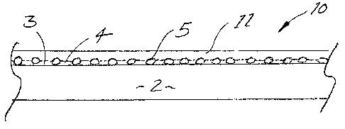
A preferred second embodiment building sheet 10 is shown in figure 2. This
embodiment is simply an enhancement of that shown in Figure 1 and accordingly
corresponding numerals have been used to denote corresponding features. As in
figure
1, the building sheet 10 has a rigid substrate 2 with a first layer of curable
resin 4 applied
to the first surface 3. This can be done with or without partial curing of the
resin prior to
the layer of reinforcing material 5 being applied thereto. The main variation
is that prior
to full curing of the resin, a further second layer of curable resin 11 is
applied on top of
the applied reinforcing material 5.
Please note that in variations to both embodiments, multiple first layers of
curable
resin 4 can be applied, with or without partial curing, prior to application
of the
reinforcing material, to build up the base coating. Similarly, in the
embodiment of
figure 2, multiple further layers of curable resin 11 can be applied on top of
the
reinforcing material, again with or without. partial curing, prior to final
curing on the
final assembly.
Of course other application methods and thicknesses can be used, such as by
wetting the reinforcement material with resin prior to placing it in contact
with the
CA 02648966 2008-10-10
WO 2007/115379 PCT/AU2007/000487
13
substrate. In this way, the reinforcing material sticks to the substrate
without having a
first base coat of resin applied to the substrate. Subsequently, a layer of
resin can be
applied to encapsulate the resin and increase the bonding between the
substrate and
reinforcing material.
It should be noted that where multiple layers of resin are applied, it is
generally
preferred to at least partially cure or mechanically key an underlying layer
of resin prior
to a further layer being applied, as this helps both the interlayer bonding
and the
application process.
This technique of several layers is useful for increasing film build and
overcoming
coverage problems or minimising defects in the underlying coats.
Referring next to figure 3, there is shown a schematic layout of an automated
manufacturing apparatus 20 specifically configured for producing the preferred
building
sheet of figure 2.
The apparatus 20 includes a simple belt or roller conveyor 21 which serves to
support the rigid substrate sheet 2 such that it's upper first face 3 is
exposed and transfer
the substrate in a downstream direction through the manufacturing apparatus.
The
conveyor 21 has a first end at a loading station 22 which is the location at
which the
prepared substrate sheets 2 are applied to the conveyor 21.
Immediately downstream of the loading station 22 is a first roller coating
apparatus 23 for applying a first layer of radiation (preferably UV) curable
resin e.g.
sealer that has adjacent thereto a first radiation (preferably LTV)
application device 24 for
optionally partially curing the sealer applied at 23.
After the radiation application device 24 a reinforcing material application
device
is provided as shown generally at 25. This device includes a feed attachment
26 for
CA 02648966 2008-10-10
WO 2007/115379 PCT/AU2007/000487
14
storing, tensioning and feeding a flexible layer of reinforcing material 5 and
an
application mechanism 27 which is adjustable to further control tension in the
material
and/or to apply pressure to push the reinforcing material onto the uncured or
partially
cured sealer coated substrate passing therebelow.
Downstream of the reinforcing material application device 25 is a second
roller
coating device or laminating device 28 for applying a second layer of
radiation curable
sealer on top of the applied reinforcing material 5. At the exit of this
second roller
coating device is one or more second radiation application devices for curing
the applied
radiation curable sealer.
In variations to this apparatus, the section marked X, comprising the first
roller
coating device 23 and first radiation application device 24, may be replicated
at least
once prior to the reinforcing material application device at 25. In this
manner, it is
possible to build up the layer of sealer before the reinforcing material is
applied.
Similarly, the section Y comprising the second roller coating device and
second
radiation application device or devices can also be replicated to build up the
sealer
applied on top of the reinforcing material. Such additional units would
preferably be
located at position Z.
In the preferred form a clear UV curable sealer is used.
This method and some limited representative variations is summarised
schematically in the following flowchart and notes. =
=
=
CA 02648966 2008-10-10
WO 2007/115379 PCT/AU2007/000487
Step 210: Apply radiation curable
coating to building sheet
Step 220: Applied coating is
partially cured with radiation
5
Step 230: Apply additional radiation
curable coating onto building sheet
10 =
Step 240: Mesh laid down onto
radiation coati ig
=
Step 250: Additional application of
radiation curable coating
Step 260: Full cure of the radiation
curable coating with radiation
=
Step 210:
In this step, a UV curable clear resin or sealer (such as that described in
the example that
follows) is applied onto the surface via a roller coater ensuring full
coverage of the panel
Step 220: [Optional]
In this step, the panel is then passed through mercury lamps at a reduced UV
dosage &
intensity to partially cure the UV clear resin
CA 02648966 2008-10-10
WO 2007/115379 PCT/AU2007/000487
16
Step 230: [Optional]
In this step, the UV clear resin is reapplied onto the panel with no UV curing
Step 240:
In this step, the glass fibre mesh is layed down onto the wet or partially/gel
cured resin
which can be patted down or left sitting on the surface
Step 250:
In this step, the panels with the glass fibre mesh passes under the roller
coater where the
mesh is pushed down to follow the contours of the surface & another layer of
resin is
applied to bind down & encapsulate the glass fibre mesh.
Step 260:
In this step, the panel passes under the UV light (at higher UV dosage &
intensity) to
fully cure the coating.
Further optional steps can be inserted between steps 250 and 260 to apply
further
coatings of LTV resin which can optionally be gel cured prior to application
of further
coats before the final cure at step 260.
EXAMPLE
Tests were conducted on a range of samples of fibre reinforced cement flooring
panels modified in accordance with the preferred form of the invention. In
each case the
sample was tested against the unreinforced base product.
The materials specifications and processing details for the samples made
according
to the invention are set out below:
Materials
Board Type James HardieTm 19mm AcittaTecTm wet area flooring
UV Sealer UV acrylate sealer ex Alczo Nobel (860301)
Mesh Type CAP80-20*20
CA 02648966 2008-10-10
WO 2007/115379
PCT/AU2007/000487
17
Further details of the mesh are provided under the section heading Reinforcing
Materials hereafter.
The flooring board panel is a medium density (approx 0.95 g/cc) cellulose
fibre
reinforced cement board, which for the purposes of these tests were unsealed.
The
control board is identified as "no mesh" in the results table. This control
board has
neither the radiation curable resin or mesh applied.
The board treated in accordance with the present invention is preferably
sanded
prior to application of the reinforcing material and radiation curable resin.
Renee the
apparent inconsistencies in the thickness between the control board and the
treated board
in the results table below.
Processing Parameters Description
lst application of UV Roller Coater Type Sorbini T/20-M Direct Roll
Coater
resin on board Roller Hardness 25 Duro
Roller Coater Speed 30 m/min
lst Coat Film Build 50-60 g/m2
Lamp Type Nordson MPS-610V CW610 Lamphead
UV Line Speed 10 m/min
2 Gel Cure
UVA UVB UVC UVV
Lamp Dose 1 (J/cm2) 0.017 0.013 0.002
0.011
Mesh placement CAP80-20*20 mesh laid onto gel cured resin coated
board then feed
3
into the roll coater
Roller Coater Type Sorbini T/20-M Direct Roll
Coater
2' application of UV Roller Hardness 25 Duro
4
resin on board Roller Coater Speed 30 m/min
2'd Coat Film Build 50-60 g/m2
Lamp Type Nordson MPS-610V CW610 Lamphead
5 F UV Line Speed 10 m/min (X 3 passes)
ull Cure
= _____________________________________________________ UVA UVB UVC UVV
Lamp Dose 2 (J/cm2) 0.403 0.310 0.056 0.291
The samples of the invention were tested against the control samples under the
following three conditions:
CA 02648966 2008-10-10
WO 2007/115379 PCT/AU2007/000487
18
Test* Conditions
Cut Direction Long dimension of specimen parallel
with
sheet long dimension
Equilibrium (EQ) Equilibrium room for 72 hours
Oven Dried (OD) Oven dried at 60 C for 48 hours
Saturated (SAT) Vacuum Saturated for 24 hours at -100
l(Pa
The 3 point flexural test was used to determine the bending strength of the
materials manufactured according to the methods disclosed herein. The diagram
below
demonstrates the configuration of the test.
LOAD
¨r
411 ________________ Sample Length
Ill_____------IP- =
SUPPORTS
(Span, S = distance between supports centres)
I.
/
Samples are tested in different conditions to give the range of properties
across
fully saturated to fully dry. Samples taken from the examples given were
tested in one or
several of the conditions being saturated, equilibrium or oven dry.
Saturated Condition (SAT)
Specimens are fully immersed in water and vacuum saturated at -100KPa for a
minimum
of 24 hrs in standard laboratory conditions.
,
CA 02648966 2008-10-10
WO 2007/115379 PCT/AU2007/000487
19
Equilibrium Condition (EQ)
Specimens are conditioned in a controlled atmosphere to 23 2 C and 50 10%
humidity
for 3 days minimum.
Oven dry (OD)
Samples were conditioned in an oven set to 60 2 C for 48hrs minimum.
Samples are tested on a MTS Q-Test Universal Testing Machine. Specimen
weight, thickness, length and width are measured before testing. The span used
for
testing the nominal 19mm thick material was 360mm. Load(N)and deflection(mm)
were
measured during the test until break occurred. The following calculations were
used to
deteimine the mechanical properties of the material.
The data from the test was then processed to derive various mechanical
properties
as described below:
A LOAD, F
/
Break Load, Fu/
...................................... , =
Proof Load, Fp e e
2'd Linearization
Point
;I/ = " ="'
1St Linearization
Point
, A
_______________________________________________________ op- DEFLECTION, D
0 Offset Proof, Break,
1.4_ Base, Do Dp Du
=
Offset
Break Load, Fu, is the maximum load sustained b the specimen.
CA 02648966 2008-10-10
WO 2007/115379 PCT/AU2007/000487
Break Deflection, Du, is the deflection, corrected to zero, at which the final
maximum load, Fu, was recorded (i.e. The deflection at which the break load is
recorded)
Linearization Points are the points on the load deflection curve used to
5 calculate zero deflection. Loads for the 1st and 2' linearization are 40%
and 60%,
respectively, of the Break Load.
Zero Deflection (0) is defined by the Linearization Points from which an
extrapolation is extended to zero load to determine the corresponding zero
deflection.
Offset Base, D40, is the deflection corresponding to the base load of 40% the
10 Break Load.
Offset is the displacement of a line drawn parallel to the line through the
linearization points to calculate the proof load. The offset is given as a
percentage of the
offset base and is 10% of D40.
Proof Load, Fp, is equal to or above the intersection of the load deflection
15 curve and a line drawn parallel to the linearization points but
displaced by the offset
deflection. The proof load may be very close to the break load in very brittle
materials.
Proof Deflection, Dp, is the deflection corresponding to the proof load, Fp.
Span, S, is the distance between the centre of the supports.
Thickness, t, is the average thickness measured at 4 points spaced out evenly
20 around the specimen.
Width, w, is the average width measured at each end of the specimen.
Mechanical Property Calculations
Modulus of Rupture (MOR) is the maximum flexural stress supported by the
specimen, and can be determined according to the following formula:
=
CA 02648966 2008-10-10
WO 2007/115379 PCT/AU2007/000487
21
MOR (MPa) = 3 Fu S
2 t2 w
Energy B is an estimate of the specific total energy absorbed by the specimen
before
breaking load. The specific total energy is proportional to the area of region
B shown on
the load/ deflection curve. This value is obtained by integration of the area
B divided by
specimen volume within the test span. (kJ/m3)
Strain Ultimate is the strain at breaking load and can be calculated by the
following
formula:
Strain Ultimate (um/m) = 6 Du t
S2
The results are set out in the table below: =
Test Test Strain Break Break
Strain Energy
Sample
Condition Span Rate Ult Thickness Width Length Mass
Density
Load Defh M.O.R.
Ult.
mm Microns/ mm mm mm g g/cm3 N mm MPa Micro Joule/m3
trim/mm
-No EQ 360 960 19.2 127.3 397 964 0.99 1258
6.9 14.5 6146 6.9
mesh
- Mesh EQ 360 975 19.5 127.3 398 970 0.98 1786
12.7 19.9 11503 18.6
CAP 80
= - No SAT 360 .1003 19.2 129.0 400 1493 1.51
810 13.0 9.2 11556 10.2
mesh
- Mesh SAT 360 976 19.1 129.0 400 1469 1.50 1118
13.9 12.9 12304 12.5
CAP80
-No OD 360 1172 18.9 130.0 400 900 0.92 1203 3.2 14.0 2788 2.4
mesh
OD 360 943 18.9 130.0 400 922 0.94 1532
7.1 17.8 6207 7.9
Mesh
CAP80
As can be seen, the sealed reinforced product has significantly improved
performance in
all measured properties. It can be seen in virtually all areas namely Break
Load, Break,
Deflection, Modulous of Rupture, Strain Ultimate and Energy B the board
treated in
accordance with a preferred embodiment of the present invention has
significantly
improved properties as compared with the control board.
CA 02648966 2013-07-15
22
MATERIAL VARIATIONS
Substrate
The rigid substrate material is preferably a moisture stable sheet material
such as
cellulose fibre reinforced cement of a density range from 0.80g/cc to 1.5g/cc.
Typical
materials are James HardieTM Fibre cement internal linings, external claddings
and sheet
flooring. When the inventiOn is used as a reinforced sheet structural flooring
material, it
is preferable to use A.5mm thick, nailable lower density fiber cement which is
lighter
weight, more workable and more nailable using conventional pneumatic and power
nailing equipment than conventional compressed fibre cement products (approx.
1.6 g/cc
dry density).
Preferably, the sheets must be strong enough to meet loading requirements for
domestic construction flooring on supporting members spaced at 450mm and 600mm
centres as specified, for example, in AS/NZS 1170.1:2002.
In line with the United States requirements, the supporting members need to be
spaced out 16 inches, 19.2 inches and 24 inch centers in the US as specified
in
ASTM E330 and E661.
The preferred fibre cement sheets may be formulated according to embodiments
disclosed in US Patent No. 6,346,146 entitled "Building Products" and also
according to
embodiments disclosed in Australian Patent No. 515151, entitled "Fibre
Reinforced
Cementitious Articles".
Most preferably, when used for structural flooring, the
sheet is configured to include connecting means such as in the form of grooves
formed
in opposite longitudinal edges of each sheet configured either to interact
with
corresponding tongues formed on edges of adjacent sheets or with a
complimentary
CA 02648966 2008-10-10
WO 2007/115379 PCT/AU2007/000487
23
elongate joining member adapted for simultaneous engagement with the
respective
adjacent grooves of adjoining sheets.
In general terms it is preferable for the face of the substrate to which the
sealer and
reinforcing is to be applied to be relatively flat. However, where this is not
possible, use
of a sufficiently flexible reinforcing material, along with a deformable or
contoured
applicating device should assist in ensuring bonding to the contoured surface.
Reinforcing Material
The reinforcing material is any continuous strand, ribbon, rod or sheet
material
of significantly higher strength and similar or higher modulus of elasticity
to that of the
substrate material where radiation curing can pass sufficiently through and/
or around
the material to cure the embedding resin sufficiently to adhere the
reinforcing material to
the sheet flooring and preferably also provide load transfer that results in
an improved
strength and toughness material by greater than 5 %. Examples of reinforcing
material
are continuous fibres such as glass fibre, alkali resistant glass fibre or
carbon fibre.
The reinforcing material may be coated or uncoated. In some embodiments the
reinforcing material may include a coating which is compatible with the
radiation
curable material to assist in adherence.
The supplier of the glass fibre used in the example described above is:-
A Jiangsu Jiuding New Material Co., Ltd., No.219 East Yuejin Road, Rugao City
Jiangsu
Province China. The glass fibres used were from this supplier were uncoated
and coated
fiberglass mesh CAP60-20*10 or polymer coated fiberglass mesh CAP80-20*20. The
technica
properties of this glass are listed below.
CA 02648966 2008-10-10
WO 2007/115379 PCT/AU2007/000487
24
Supplier Item Number = CAP60-20*10 CAP80-20*20
Weave: Plain Plain
=
Material (Tex): Warp 224'14'2 22*1*2
Weft 44 44
Density (counts per inch): Warp 20 20
Weft 10 20
Unit Weight (g/m2) Raw 54 5 69 5
Finished Product 60 5 80 5
Content of Resin: 2%
Tensile Strength (N/50mm): Warp _?_650 ~1 130
Weft 1130
Tensile strength after 28 days conditio Warp _.60% of original ._60% of
original
in 5% NaOH: Weft .60% of original ._60% of
original
The uncoated mesh was found to be more pliant and better able to follow
irregularities in the base sheet.
Radiation Curable Material
The radiation curable material, resin or sealer is applied in layers which may
be
from 1 to 1000um thick, with 5 to 2001.Lm being more preferable and 10 to
1201im being
most preferred. The curable or polymerisable components used in forming the
radiation
curable materials and blends of the present invention include, but are not
limited to,
urethane, acrylic, epoxy and polyesters or compounds having multiple
functional types =
such as polyester epoxies and urethane acrylics.
The curable or polymerisable components may be monomers, oligomers or
polymers. The oligomers are prepared from a=range of monomers with
functionality
including, but not limited to, isocyanate, hydroxyl, polyether, epoxy,
carboxylic aeid and
ethylenic unsaturation. The monomers used in such a composite, include but are
not
limited to acrylate functionalized alcohols, diols and polyols, acrylate
functional
=
CA 02648966 2008-10-10
WO 2007/115379
PCT/AU2007/000487
ethoxylated and/or propxylated alcohol, diols and polyols, and acrylate
functional
ethylene and propylene glycols and ethylene and propyelene polyglycols. Other
monomers effective in preparing such composites include but are limited to
derivatives
of unsaturated carboxylic acids and diacids such as acrylate, methacryalte,
maleate and
5 fumarate esters, and vinylic functional materials such as vinyl ethers,
and vinyl
pyrolidones. Blends or mixtures of the polymerisable components as herein
described
may also be used.
It is particularly preferred to use polymerisable compounds based on including
ethylenically unsaturated monomers.
10 It is preferable that the curable resin compositions used in the
present invention
have high solids content. Particularly, it is preferred that the curable resin
has a solids
content higher than 50%, more preferably higher than 70% and even more
preferable if
the resin forming compositions have a solids content of around 80-100%.
It is preferable to use a combination of lower molecular weight monomers and
15 higher molecular weight oligomers in order to achieve the most desirable
viscosity for
application, the best cure behaviour once exposed to radiation, and the most
desirable
physical and mechanical properties once cured. Lower molecular weight monomers
may be present in amounts ranging from 10 ¨ 50% by weight, with 10 ¨ 30% being
more
preferable, and 15 ¨ 25% being most preferred. Higher molecular weight
oligomers may
20 be present in amounts ranging from 10¨ 50% by weight, with 15 ¨ 40%
being more
preferable, and 20 ¨ 35% being most preferred.
If inorganic filler is used, it may be present in amounts ranging from 5 to
80% by
weight on the basis of the whole, whereas surface treatment additives are
preferably used
CA 02648966 2008-10-10
WO 2007/115379 PCT/AU2007/000487
26
in amounts ranging from 0.01 to 2% by weight, with respect to the filler, and
from 0.01
to 0.5% by weight, with respect to the whole of the composition.
The above mentioned polymerisable compounds can be used as such or in
mixture with additives such as catalysts, photo initiators, mineral or organic
fillers, anti-
wetting agents, dyes, plasticizers, pigments, stabilizers, shockproofing
agents, insulating
agents, flame retarding agents and the like, which are added in order to
improve the
physical-chemical properties of the finished product.
Examples of radiation curable material/resin/sealer:
1. A commercially available radiation curable resin such as UV sealer: Akzo
Nobel
.10 Clear Sealer R60301-001
2. A specifically formulated UV sealer such as that described in the table
below:
UV Sealer Composition %w/w Description Supplier
, Supplier Location
Tripropylene Glycol Diacrylate 20 SR306 Sartomer Hong Kong,
China
= (TPGDA)
Bisphenol A Based Epoxy 29 CN120 Sartomer Hong Kong,
China
Acrylate
Anti-Settling Additive 0.40% Byk 410 Byk-Chemie Wesel,
Germany
2-Hydroxy-2-Methyl-1- 1.80% Darocur 1173 Ciba NSW,
Australia
Phenylpropan-l-one
2,4,6-Trimethylbenzoyl- 1.50% Lucirin TPO BASF Victoria,
Australia
Diphenyl-Phosphineoxide
Calcium Carbonate 46.8% Omyacarb 20 Omya Australia NSW,
Australia
Defoamer 0.50% Byk077 Byk-Chemie Wesel,
Germany
Different techniques can be used for the preparation of the composite sheets.
For
example, a radiation curable compound may be flood coated, roller or brush
coated or
spray coated onto fibre cement.
To cure a UV curable form of the resin at a film build of 40 ¨ 50 gsm a UV-A
dose of at least 0.15J/cm2 is required for full cure and a UV-A intensity >1
W/cm2 . At
CA 02648966 2008-10-10
WO 2007/115379 PCT/AU2007/000487
27
60 m/minute this equates to 3 medium pressure mercury lamps running at a power
input
of 450W/inch.
The preferred forms of resin/sealer are curable by UV, infra-red, or near
infra-
red.
In one example of the invention formation process, a fibre cement board is
coated with a radiation curable material and a glass fibre mesh is immediately
placed on
top, this can then be cured with a suitable radiation source such as UV.
In another example the fibre cement board is coated with a radiation curable
material which is partially radiation cured with just enough dose to create a
tacky
surface. A glass fibre mesh is applied to the tacky surface and a subsequent
layer of
radiation curable material is applied over the glass fibre mesh, and fully
cured with a
suitable radiation source.
In another embodiment the radiation curable material is a pressure sensitive
adhesive. Such pressure sensitive adhesives which are radiation curable are
known but
have not been used for the purpose described. Suitable formulations include:
= a hydrogenated polybutadiene liquid oligomer (100 pts by wt) which has
one
or more ethylenically unsaturated terminal radicals, and a chain transfer
agent
(0-20 pts by wt).
= an oligomer having one or more acrylic double bonds in its molecule (100
pts
by wt), a chain transfer agent (0-20 pts by wt)and an aliphatic polar monomer
having a carboxyl group (0-30 pts by wt).
= poly (vinyl alkyl ether) oligomer, a liquid monoacrylate monomer and
photoinitiator.
= polystyrenic block copolymers;
CA 02648966 2008-10-10
WO 2007/115379 PCT/AU2007/000487
28
= epoxyfunctional liquid rubbers
METHOD OF MANUFACTURE
While the methods and apparatus detailed herein are ideally suited to
achieving
simultaneous sealing and reinforcing of the substrate, it will be appreciated
that in the
broadest form sealing of the substrate need not be achieved. Accordingly, the
invention
in at least one aspect is intended to include all methods by which a
reinforcing material
is adhered to a rigid substrate using a radiation curable resin. For example,
rather than
applying a full sealing coating of the resin to the substrate, a pattern of
resin may be
applied sufficient only to bond the reinforcing material to the substrate.
Alternatively,
the resin may be applied to the reinforcing material by methods such as
dipping, rolling
or spraying, prior to the reinforcing material being brought into bonding
contact with the
board. Such methods may include the steps of applying multiple layers of
resin, with or
without intermediate partial cure or gel cure steps along the lines outlined
herein.
ADVANTAGES OF INVENTION
The invention in one of its broadest forms provides a simple but effective
method
of providing a building element with enhanced strength characteristics
achieved by
adhering a reinforcing material to a rigid substrate using a radiation curable
resin. The
use of a radiation curable resin as the adhesive makes the manufacturing
process easy to
automate as a continuous process and is readily adapted for most substrates
and
particularly suited for use with the preferred substrate fibre reinforced
cement.
Similar advantages are obtained with that form of the invention that uses a
meltable and resettable polymer solely to adhere the reinforcing material to
the rigid
substrate.
CA 02648966 2008-10-10
WO 2007/115379 PCT/AU2007/000487
29
The invention in its preferred forms provides a very simple cost and time
effective
means of both sealing and simultaneously reinforcing building materials so as
to
improve their water resistance and strength characteristics.
This can result on the one hand, in products of only slightly increased
thickness
having substantially improved strength characteristics, which increases their
potential
range of applications, in that the products are potentially less brittle,
easier to handle and
more durable in terms of improved weather resistance and impact resistance.
Alternatively, the invention can be used to provide products having at least
equivalent or potentially better strength characteristics to existing
products, but in a form
that is lighter in weight and easier to transport and handle.
The invention has particular advantages when applied to the specific field of
, structural flooring for use in wet area flooring and external decking. In
this regard, fibre
cement materials are potentially suited to such applications in terms of their
durability
and resistance to rot but the brittle nature of fibre cement and its reduced
load bearing
capabilities when wet, does in many ways limit its applications. However, as
can be
seen from the example above, modification of these basic flooring substrates
in
accordance with the invention, dramatically improves the strength
characteristics of
these boards. This also facilitates extended use of fibre cement products in
decking
applications where there may be some current resistance due to the brittleness
of the
base product. By having an integral reinforcing material, the product will be
less prone
to brittle type failure, but where this does occur the reinforcing may act to
retain the
fragments of the substrate in a similar manner to laminated glass products.
As mentioned above the building element of the present invention is
particularly
suitable for structural flooring as it does not require a tile backerboard to
adhere tires to
CA 02648966 2008-10-10
WO 2007/115379 PCT/AU2007/000487
the structural flooring. Similarly, the element is suitable for external
decking due to the
inventive synergistic combination of moisture resistance and increased
structural
integrity.
The invention also allows more conventional fibre cement products to be
readily
5 adapted for use in impact resistant walling applications such as is
required in hospitals
and schools.
Another advantage of the invention is that the applied reinforcing helps to
resist
edge break out when nailing the perimeter of a building sheet, or when the
fastened sheet
is exposed to shear or racking forcing when fastened to framing.
10 It should be mentioned, that while the invention was developed primarily
for use
with fibre cement substrate materials, it can clearly be seen that it will
have useful
application with a variety of other base materials including manufactured
wood,
plywood etc.
Similarly, while the invention has been described in relation to the preferred
15 application to building sheets and building panels, the invention can be
applied to non-
planar building elements made from similar materials such as trim components
and the
like, the reinforcing elements serving to increase bending strength and
thereby improve
handle-ability etc.
Although the invention has been described with reference to specific examples
it
20 will be appreciated by those skilled in the art that the invention may
be embodied in
many other forms.