Note: Descriptions are shown in the official language in which they were submitted.
CA 02648967 2013-12-20
1
METHOD AND APPLIANCE FOR COLLECTING ROPE
FIELD OF THE INVENTION
The present invention relates to a method for collecting rope
and an appliance for collecting rope.
BACKGROUND OF THE INVENTION
The solution according to the invention is particularly suited
to collecting the old rope in conjunction with replacing the
hoisting ropes of elevators. The hoisting ropes used in
elevators wear in use and can even break when they are worn. For
this reason the safety regulations for elevators require that
the hoisting ropes in elevators with hoisting ropes must be
replaced with new ones at certain intervals, or at least if
obvious wear or damage is observed. According to prior art the
hoisting roping is generally replaced by first removing the old
hoisting ropes and after that installing the new hoisting ropes.
A drawback of this solution is that replacement of the roping
with this method is awkward and takes a lot of time. Especially
in elevators in which the suspension ratio is great, e.g.
between 4:1-12:1, replacing the ropes with this conventional
method is very awkward and slow owing to the numerous diverting
pulleys and large rope lengths, nor is it always necessarily
safe.
Prior art also includes solutions in which the new ropes are
drawn into position by means of the old hoisting ropes. In this
case the ends of the old hoisting ropes are detached and the new
ropes are attached to their free ends, after which the new ropes
are guided into place by pulling on the old ropes. A problem is
that this method is only suitable for thin and relatively short
CA 02648967 2013-12-20
,
,
2
ropes, which are so light that they can be pulled into position
by human muscle power. This method is not suited to thick and
long hoisting ropes.
One prior-art method is to use a pulling device made for this
purpose to pull the ropes, which pulls the old ropes out of
their position and simultaneously pulls the new ropes into their
position. One problem with this is where to lead the old ropes
when they are pulled out of their position. One solution is that
the ropes are allowed to freely pile up on the bottom of the
elevator shaft, onto a certain floor or into some other room. A
problem with this solution is that the ropes do not pile up
evenly or tidily, they take a lot of space and the ropes can
easily become entangled. The ropes also make the room into which
they are led dirty. Another solution is to wind the old hoisting
ropes either manually or mechanically onto a rotatable reel.
When using a manually wound reel, one problem is that an extra
person is needed to rotate the reel, which increases the costs
of replacing the roping. In addition manual winding is
unergonomical work and can possibly also jeopardize work safety.
When using a mechanically wound reel, one problem is that the
reel possibly needs its own separate power source, which further
increases costs. A further problem is that feeding the rope and
winding the old rope, i.e. waste rope, does not necessarily work
in synchronization, in which case the rope does not necessarily
wind onto the reel evenly and tidily. One solution, in which the
old hoisting ropes are wound onto a separate reel, is presented
in the Japanese patent publication no. JP2003146556. This
solution, however, contains the aforementioned problems.
Another Japanese patent publication, no. JP2003238047, presents
a different type of solution, in which the old hoisting ropes
CA 02648967 2015-04-29
3
are also wound onto a reel. In this solution the reel intended
for winding the waste rope is connected to the reel feeding the
new rope and both reels are rotated by the same machine. One
advantage of this is that a separate machine is not needed for
the second reel and the reels rotate in synchronization with
each other. A drawback, however, is that the machine must be
more powerful in order to be able to rotate both reels and this
increases costs. Another drawback is one relatively large
package that is awkward to handle, which contains a reel for
both the old and the new ropes. Yet another drawback is the
difficulty of synchronization, because there is a different
amount of rope on the reels in different situations, in which
case the dimension of the relative circumference of the reels
changes. Some technical solution with at least switches and/or
gears is needed for synchronization, so as a consequence the
solution is expensive and complex, and also more susceptible to
malfunction and requires servicing.
Furthermore a problem in all the aforementioned winding
solutions is that the dirt and grease detaching from the old
hoisting ropes easily make a mess of the room in which the
winding takes place. This causes extra cleaning work and also
disturbs any people possibly working or moving in the winding
rooms, if the winding is performed e.g. on a floor level.
SUMMARY OF THE INVENTION
The present invention aims to mitigate the aforementioned
drawbacks and to achieve a simple and low-cost method and
appliance for collecting the rope. The purpose of the invention
is also to achieve a solution by means of which the old hoisting
ropes can easily be collected onto a tidy reel in conjunction
with replacement of the hoisting roping. The purpose of the
CA 02648967 2015-04-29
4
invention is also to improve the ergonomics, safety and tidiness
of rope replacement work and to reduce labor costs.
Accordingly, as an aspect of the present invention, there is
provided an appliance for collecting the old elevator hoisting
rope in conjunction with the replacement of hosting ropes of
elevators, which appliance comprises at least a collection
container for the old hoisting rope, in which the rope to be
collected is fitted to be disposed includes a tubular guide
element, through which the rope to be collected is fitted to be
led into the collection container wherein: the collection
container for the old hoisting rope is provided with an axis of
rotation, and in that the collection container is fitted to
rotate around the axis of rotation pushed by the rope to be
collected; the appliance comprises a rope pulling device, which
comprises at least a base, to which at least one pulling disk is
attached, which pulling disk corresponds to the hoisting rope,
and onto which pulling disk the hoisting rope can be fitted, at
least one guide roll for holding the hoisting rope in position
in the pulling disk, a tightening element for moving the pulling
disk in relation to the guide roll and for tightening it into
position on the base and to which appliance at least one
electric motor for rotating the pulling disk is fitted, and the
first end of the tubular guide element is fixed in conjunction
with replacement of the elevator rope to the rope pulling device
such that the old hoisting rope to be removed can be pushed
through the guide element into the collection container with the
rope pulling device.
In the method according to the invention the rope to be
collected is arranged to be collected in a collection container.
The method is wherein the rope to be collected is pushed into
CA 02648967 2015-04-29
4a
the collection container in such a way that the collection
container is made to rotate around its axis of rotation by means
of the pushing force of the rope.
The axis of rotation is described hereafter as a concrete axis,
but it can also be conceptualized as an abstract axis of
rotation-i.e. as the center axis of a concrete axis.
The method according to one preferred embodiment is wherein
before being pushed into the collection container the rope to be
collected is led into a tubular guide element, which is fitted
to guide the rope into the collection container at an inclined
and essentially downward-oriented angle.
The method according to a second preferred embodiment is wherein
in conjunction with the replacement of the elevator rope, the
rope to be collected is the old hoisting rope to be removed,
which is pushed into the collection container through the guide
element with a rope pulling device or by means of gravity, at
the same time as the new rope is pulled into position by means
of the old rope.
The method according to a third preferred embodiment is wherein
the rope to be collected is a rope passing through a Tirak hoist
or similar hoist, the free end of which rope is pushed through
the guide element into the collection container with the Tirak
CA 02648967 2013-12-20
,
,
hoist or with a similar hoist, at the same time as hoisting work
is performed with the hoist.
_
The method according to a yet another preferred embodiment is
5 wherein new rope is fed to the elevator and/or any old hoisting
rope is pulled out of the way of the new rope with the rope
pulling appliance that acts on the hoisting rope. The rope
pulling appliance according to yet another preferred embodiment,
with which the rope to be handled is moved, comprises disks
pressed towards each other, between which the rope is guided.
The invention also relates to an appliance for collecting rope.
The appliance comprises at least a collection container, in
which the rope to be collected is fitted to be disposed. The
appliance according to the invention is wherein the collection
container is provided with an axis of rotation, and in that the
collection container is fitted to rotate around its axis of
rotation while pushing the rope to be collected.
The appliance according to one preferred embodiment is wherein
the appliance comprises a tubular guide element, through which
the rope to be collected is fitted to be led into the collection
container.
The appliance according to a second preferred embodiment is
wherein the guide element is trough-shaped, in which case the
rope to be collected is fitted to be led into the collection
container along the base and the side edges of the trough-shaped
guide element.
The appliance according to a third preferred embodiment is
wherein the second end of the guide element is fixed immediately
CA 02648967 2013-12-20
6
above the collection container in such a position with respect
to the collection container that the tubular guide element is
fitted to guide the rope into the collection container at an
inclined and essentially downward-oriented angle.
The appliance according to another preferred embodiment is
wherein the first end of the guide element is fixed in
conjunction with replacement of the elevator rope to the rope
pulling device such that the old hoisting rope to be removed can
be pushed through the guide element into the collection
container with the rope pulling device.
The appliance according to another preferred embodiment is
wherein the collection container is a cylindrical containers
essentially open at the top, provided with a base and an upward-
oriented flange.
The appliance according to yet another preferred embodiment is
wherein a guide element holding the rope in the container is
arranged on the upper edge of the collection container, such as
one or more separate guide elements or a conical or trough-
shaped bending made inward to the edge of the collection
container.
The appliance according to yet another preferred embodiment is
wherein the collection container is provided with a plastic bag
or with a similar bag, and in that the old hoisting rope is
fitted to wind directly into the bag in the collection
container.
The appliance according to yet another preferred embodiment is
wherein the appliance comprises a rope pulling appliance, which
CA 02648967 2013-12-20
=
7
comprises at least a base, to which at least one pulling disk is
attached, which pulling disk corresponds to the hoisting rope,
and onto which pulling disk the hoisting rope can be fitted, at
least one guide roll for holding the hoisting rope in position
in the pulling disk, a tightening element for moving the pulling
disk in relation to the guide roll and for tightening it into
position on the base, and to which appliance at least one
electric motor for rotating the pulling disk is fitted.
Some inventive embodiments are also discussed in the descriptive
section and in the figures of the present application. The
inventive content of the application can also be defined
differently than in the claims presented below. The inventive
content may also consist of several separate inventions,
especially if the invention is considered in the light of
expressions or implicit sub-tasks or from the point of view of
advantages or categories of advantages achieved. In this case,
some of the attributes contained in the claims below may be
superfluous from the point of view of separate inventive
concepts. Likewise the different details presented in connection
with each embodiment of the invention can also be applied in
other embodiments.
One advantage of the solution according to the invention is that
when changing the hoisting roping the old hoisting ropes can be
easily wound onto a reel automatically and in synchronization
without a separate power source. Another advantage is that the
winding work is more ergonomic, safer, tidier and cheaper than
when done with prior-art methods. A further advantage is that
the winding appliance is simple and inexpensive to implement.
Yet another advantage of the invention is the opportunity to use
the solution according to the invention also for other rope
CA 02648967 2013-12-20
8
collection purposes. For example a free rope end passing through
a Tirak hoist or similar hoisting appliance can be collected
and/or discharged neatly by means of the invention.
BRIEF DESCRIPTION OF THE DRAWINGS
In the following, the invention will be described in more detail
by the aid of one of its embodiments with reference to the
attached drawings, wherein
FIG. 1 presents a simplified side-view of a traction sheave
elevator with counterweight, in which the solution according to
the invention can be used,
FIG. 2 presents an elevator according to FIG. 1, in which the
hoisting roping is currently being replaced,
FIG. 3 presents another elevator, in which the hoisting roping
is currently being replaced and
FIG. 4 presents an appliance for collecting rope according to
the invention.
FIG. 5 presents the rope pulling appliance of the appliance
according to the invention
DETAILED DESCRIPTION OF THE PREFERRED EMBODIMENTS
FIG. 1 presents a simplified side view of a traction sheave
elevator equipped with hoisting roping 3 comprised of parallel
hoisting ropes and with a counterweight 9, in which the solution
according to the invention can be used. The elevator car 2 is
suspended on the hoisting roping 3 and it is fitted to move
CA 02648967 2013-12-20
9
backwards and forwards in the elevator shaft 1 along guide rails
4 in an essentially vertical direction. The elevator receives
its lifting power from a hoisting machine 5 provided with a
traction sheave 6, which is connected at least to an elevator
control system 8. The first end of the hoisting roping 3 is
fixed to the fixing element 12 disposed in the upper part of the
elevator shaft 1, from where the hoisting roping is led to pass
first under the elevator car 2 around the diverting pulley 14 to
the traction sheave 6 of the hoisting machine 5 in the upper
part of the elevator shaft, from where the hoisting roping 3 is
further led to travel to the diverting pulley 11 of the
counterweight 9, and after passing around the diverting pulley
11 the roping is led to the fixing point 13 disposed in the
upper part of the elevator shaft, to which the second end of the
hoisting roping is fixed. The elevator shaft 1 in FIG. 1 is
truncated in such a way that of the floor levels only the
bottommost, the next to topmost and the topmost floor 15 are
visible. The rope suspension can of course also be different to
that described.
FIG. 2 presents an elevator according to FIG. 1, in which the
old hoisting roping is currently being replaced with new
hoisting roping. The hoisting roping is replaced in this case
such that the new parallel hoisting ropes are pulled one at a
time into position by means of the old hoisting ropes and a
pulling device 18 suspended from a suitable fixed point, from
which the pulling device is suspended in position in the
preparation phase of the replacement. Preferably the pulling
device 18 is suspended e.g. on the ceiling of the elevator shaft
or on the suspension point 32 on the beam situated close to the
ceiling by means of a suspension rope, a suspension chain or a
similar support element 33.
CA 02648967 2013-12-20
In the preparation phase of the replacement the elevator car 2
is also driven to a location in the shaft suited to the
replacement, which in the elevator of the example is in the
5 upper part of the elevator shaft. After this the counterweight
is supported in position, the car is lifted upwards e.g. with a
block and tackle to achieve a suitable overtravel distance and
the car is locked into its position by means of the safety
gears. The elevator car 2 is driven e.g. to a location where the
10 roof of the car is essentially at the level of the topmost floor
and the car is locked into position e.g. by means of the
safety gear 7 of the elevator. In addition the stationary
position is ensured with a safety chain or in another suitable
manner. Correspondingly the counterweight 9 is in this case in
15 the lower part of the elevator shaft 1, where it is supported
e.g. on the floor of the shaft by means of support elements 22.
When the elevator car 2 is locked into position, the pulling
device 18 is fastened to the rope to be replaced 3b on both
sides such that the rope leaving the traction sheave 6 of the
elevator machinery down to the counterweight 9 is fitted between
the pulling disks of the pulling device 18 and the support rolls
on the left-hand side of the pulling device 18 and
correspondingly the rope going up from the counterweight 9 to
the fixing point 13 is fitted between the pulling disks of the
pulling device 18 and the support rolls on the right-hand side
of the pulling device 18. Before starting the replacement the
hoisting ropes of the new hoisting roping that is still on reels
16 are taken to the roof of the elevator car 2 or to another
suitable place, e.g. to a floor.
When everything is ready for starting the replacement the first
old hoisting rope 3b is cut below the fixing point 13 of the
CA 02648967 2013-12-20
11
second end and the cut end of the rope remaining above the
pulling device 18 is threaded into the tubular guide element 20
of the rope collection appliance 19 from the free end of the
guide element, after which the free end of the guide element is
fastened to the top part of the pulling device 18. After this
the same old rope 3b is cut from its fixing point 12 of the
first end, i.e. on the side of the elevator car 2, and the new
rope 3a is joined to the cut end of the old rope 3b by means of
a joint element. After this the new rope 3a is pulled into its
position by means of the pulling device 18 and the old rope 3b.
At the same time the old rope 3b is allowed to wind through the
guide element 20 to the collection container 21 of the rope
collection appliance situated on the topmost floor 15.
Pulling of the ropes 3a and 3b with the pulling device 18 is
continued until the joint location 17 of the ropes comes through
the pulling device and the guide element 20 so far that the end
of the new hoisting rope 3a definitely reaches the fixing point
13 after the rope is removed from the pulling device 18 and the
guide element 20. After this the pulling device 18 is stopped
and the new hoisting rope 3a is cut at a suitable point. The end
of the guide element 20 is detached from the pulling device 18
and the end of the new hoisting rope 3a is pulled out of the
guide element 20, cut such that the old rope 3b detaches from
the new rope 3a and the new rope 3a is fixed to its fixing point
13. Next the new hoisting rope 3a is suitably cut also at its
end on the side of the elevator car 2 and fixed to its fixing
element 12, after which the rope is freed from the pulling
device 18. All the parallel hoisting ropes are replaced with the
same method and. finally the rope tightnesses are equalized such
that no loose sections remain in the new hoisting roping. After
this the elevator car 2 and the counterweight 9 are detached
CA 02648967 2013-12-20
,
12
from their supports and driven the necessary equalization runs
and if necessary the rope tightnesses are again equalized and
other necessary finishing procedures are performed.
In the situation presented by FIG. 2 the pulling device 18 has
had time to pull the rope some distance so that the joint
location 17 of the old and the new hoisting rope is slightly
above the diverting pulley 14 situated below the elevator car 2.
FIG. 3 presents a diagrammatic and simplified view of an
elevator with 1:1 suspension and the replacement of the hoisting
ropes to be performed in it, in which the replacement is
currently in progress. The hoisting roping is replaced in this
case such that the new parallel hoisting ropes 3a are pulled one
at a time into position by means of the old hoisting ropes 3b.
In FIG. 3 the position of the old hoisting rope that is still in
place is presented with a dashed line. At least the following
actions have been performed in the preparation stage: the
elevator car 2 has been locked to the guide rails close to the
topmost floor e.g. with the safety gear and the stationary
position has additionally been ensured with at least one safety
chain 34 or in another suitable manner. Correspondingly the
counterweight 9 is in this case in the lower part of the
elevator shaft 1, where it is supported e.g. on the floor of the
shaft by means of support elements 22. In addition the reels 16
of the new hoisting ropes are disposed on the topmost floor or
in another suitable location and the rope collection appliance
19 according to the invention is disposed in the lower part of
the shaft 1, e.g. on the bottom of the shaft, the tubular guide
element 20 of which rope collection appliance, or at least the
top part of it, is placed in an essentially vertical position
and the top end of the guide element is e.g. fixed to the top
CA 02648967 2013-12-20
=
=
13
edge of the counterweight such that the old hoisting rope 3b can
be threaded from above inside the guide element 20 from the
mouth aperture.
When the preparations are completed the first old hoisting rope
3b is cut above the elevator car 2 and the new hoisting rope 3a
coming from the reel 16 is joined to the cut end. After this the
old hoisting rope 3b is cut above the counterweight 9 and the
cut end is threaded from the top end of the tubular guide
element 20 inside the guide element. When after this the new
rope 3a is released from the reel 16 the old rope 3b slides
under its own weight along the guide element 20 into the
collection container 21 of the collection appliance 19, pulls
the new rope 3a along with it, rotates the collection container
around its axis of rotation 29 and winds onto the inner edge of
the collection container 21 in the same way as earlier described
in the example.
When the new rope 3a has come far enough, the pulling is stopped
and the rope is cut at both ends and the ends are fixed in their
positions on both the elevator car 2 side and the counterweight
9 side. All the parallel hoisting ropes are replaced with the
same method and finally the rope tightnesses are equalized such
that no loose sections remain in the new hoisting roping. After
this the elevator car 2 and the counterweight 9 are detached
from their supports and the necessary equalization runs are
driven and if necessary the rope tightnesses are again equalized
and other necessary finishing procedures are performed.
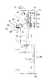
FIG. 4 presents an appliance 19 according to the invention for
collecting the old rope as well as the rope pulling device 18.
The pulling device 18 comprises e.g. two pairs of pulling disks
CA 02648967 2013-12-20
14
27, on the sides of which are fitted support rolls 28. The
pulling device 18 is arranged to operate such that the rope to
be pulled is placed and compressed between the pulling disks and
the support rolls, and when the pulling disks 27 are rotated the
pulling device 18 pulls the rope between the pulling disks and
the support rolls. The pulling appliance is described elsewhere
in the present application.
The guide element 20 included in the appliance 19, which in this
presented embodiment is e.g. a plastic pipe, is fitted to be
fixed at its first, i.e. free, end 30 to the top part of the
pulling device 18 by means of the fixing element 25. The fixing
element 25 can be e.g. a sleeve, through which the hoisting rope
3b is led inside the guide element 20 when the rope begins to be
pulled with the pulling device 18. The appliance 19 also
includes a collection container 21, which can be placed e.g. on
the floor of a landing or in another suitable location resting
on its support structure 23. The collection container 21 is a
cylindrical container, essentially open at the top, provided
with a base and an upward-oriented flange. The old rope staying
in the collection container 21 during the replacement can be
ensured with the shape of the flange of the collection container
or with separate guide elements. The flange can be e.g. of
conical shape tapering upwards or on the top edge of the flange
can be a trough-like or similar bending made inwards.
The support structure 23 comprises four e.g. metal supporting
legs, which join under the centre point of the collection
container 21 and the collection container 21 is fixed at
essentially the centre point of its base to the support
structure 23 by means of both the axis of rotation 29 and the
fixing element 26 such that the collection container 21 can
CA 02648967 2013-12-20
rotate freely around its essentially vertical axis of rotation
29. The collection container 21 is either fastened with bearings
to the axis of rotation 29 or the collection container is fixed
to the vertical axis 29 and the vertical axis 29 is fastened
5 with bearings to the support structure 23. A support element 24,
which is also made e.g. of metal, is fixed at its first end to
one of the legs of the support structure 23. The support element
24 is fitted to extend at its free end suitably over the
collection container 21 and the second end 31 of the guide
10 element 20 is fixed to the free end of the support element 24 at
an inclined attitude both vertically and horizontally to the
inner surface of the cylindrical part of the collection
container. In this case the second end 31 of the guide element
is at such an angle in relation to the inner surface of the
15 cylindrical part that the rope coming through the guide element
meets the inner surface of the flange of the collection
container 21 substantially almost tangentially and at the same
time is directed downwards.
20 The appliance 19 according to the invention operates in such a
way that when the pulling device 18 starts to pull the old
hoisting rope 3b out of its position and at the same time the
new hoisting rope 3a into its position, the pulling device 18
pushes the old rope 3b inside the guide element 20 from the
first end of the guide element. When the pulling device 18 has
pulled the new rope some distance, the old rope 3b has passed
inside the guide element 20 to the second end 31 of the guide
element. When the end of the old hoisting rope 3b comes out of
the second end 31 of the guide element 20, it is led into the
collection container 21 at a suitably inclined acute angle so
that the end of the rope meets the inner surface of the
cylindrical part of the collection container 21 at an inclined
CA 02648967 2013-12-20
=
=
16
angle, in which case the collection container 21 starts to
rotate as a result of the force transmitted by the rope around
the axis of rotation 29 at the same time winding the old
hoisting rope 3b inside it as the rope comes out of the guide
element 20. The appliance 19 thus operates in synchronization
with the pulling device 18 and a dedicated power source in it is
not required.
According to one preferred embodiment the rope pulling device 18
does not need to be against the guide element 20 as presented in
FIG. 4 or in its vicinity. In these kinds of situations the rope
is led into the collection container 21 via the guide element 20
by means of gravity and the pulling device 18 can be elsewhere
in the elevator shaft than in the vicinity of the guide element
20 that feeds the rope.
With the method according to the invention the rope is collected
e.g. as follows: at first the rope 3b is led inside the guide
element 20 from the first end 30 of the guide element. After
this the rope 3b is pushed forward inside the guide element 20
until the end of the rope 3b comes out of the second end 31 of
the guide element. From here the rope 3b is pushed into the
collection container 21 at a suitably inclined downward angle
such that the rope meets the inner surface of the collection
container 21 and the collection container 21 is made to rotate
around its axis of rotation 29 by means of the pushing force of
the rope 3b. Pushing of the rope 3b into the collection
container 21 is continued for the desired time, during which the
rope 3b winds into a tidy coil inside the collection container
21.
CA 02648967 2013-12-20
17
The collection container 21 can also be equipped with a plastic
bag or with a similar bag, in which case the old hoisting rope
is fitted to wind directly into the bag in the collection
container 21. In this case the old rope can be collected tidily
and the whole rope is in a bag, the bag containing the rope is
removed and a new bag is placed in the collection container for
the next rope. By means of the bag the rope can easily be
transferred to further handling.
According to one embodiment instead of a tubular guide element
the guide element can be at least partly another shape than a
tube. In this case the guide element can be e.g. trough-shaped
so that the rope is guided into the collection container along
the bottom and the side edges of the trough of the guide
element. The collection container can also be a basket or
similar or also a temporary container constructed in a frame,
e.g. a container that has a detachable base or an edge piece of
the frame that can be bent inside.
FIG. 5 presents a diagrammatic illustration of a rope pulling
device 18 according to the invention. The rope pulling appliance
of the rope collection appliance according to the invention is
based on traction through friction, which is achieved by
compressing with the desired spring force one or more two-part
pulling disks such that the disks 38, 39 press against each
other. The disks 38, 39 are shaped such that the rope endeavors
to run on the outer rim of the pulling disk. This is preferably
implemented such that the edges of the disks on the rim side are
beveled, at least at the point where they face each other, in
which case a gap remains between the disks 38, 39 in the manner
illustrated in FIG. 5, which widens towards the rim. The disks
38, 39 seek by means of the force of the spring 35 a state of
CA 02648967 2013-12-20
18
equilibrium for themselves and for the rope between them wherein
the rope travels between them and rests against the guide rolls
28, by means of especially the radial force component produced
by the bevel. The appliance thus contains guide rolls 28 on the
outer rim of the disks, with which the rope is kept between the
disks 38, 39 during pulling of the rope and by means of which
the rope is deflected such that a controlled contact is achieved
between the rope and the pulling disk 30, 31. The grip of the
appliance is based on spring force, which can be achieved in a
controlled and repetitive manner, after placement of the rope,
and which is implemented by means of the tightening spring 35.
The tightening spring 35 is preferably situated in the manner
illustrated in FIG. 5 outside the disk stack formed by the disks
38, 39 on the axis of rotation of the disks to co-axially press
the disks towards each other. In this case the rope groove
formed between the disks is able to adapt to fluctuations in the
thickness of the rope, because the disks 38 and 39 can move
axially in respect to each other against the spring force of the
tightening spring 35. The rope pulling device can contain more
than one pulling disk. For example, it is also possible to
manufacture a version of the rope pulling device 18, with which
all the ropes can be pulled simultaneously. When there are more
than one pulling disk 30, 31, they are preferably joined by a
power transmission 48, which is preferably a chain, a belt, a
cogged belt or a rack and pinion.
The guide rolls 28 are preferably situated on two sides of the
pulling disk 30, 31 in opposing positions to each other. In this
case the rope feeding device 18 can move ropes on opposite sides
of the pulling disk simultaneously in different directions. Of
course the device can also be utilized such that only one side
is used, in which case the roll on the other side is not needed.
CA 02648967 2013-12-20
=
=
19
In the figures 3 units of the guide rolls are presented on both
sides of the pulling disk, but it is obvious that there can be a
different amount of them, e.g. one or more, but preferably 2
units on both sides. The rolls according to one preferred
embodiment might reach partly between the disks 38, 39. The rope
can consequently pass more deeply between the disks 38, 39, in
which case the passage of especially a rope extension is
facilitated. This can be implemented such that the guide roll 28
is so narrow that it fits between the disks 38, 39.
Alternatively the guide roll tapers towards the outer rim or
includes on its outer surface a narrower ridge than the gap
between the pulling disks. Yet another method of implementation
is to install a separate bushing around the guide roll 28 to
form a narrow section on the rim of the disks.
Properties of the rope pulling device:
-It is possible to pull/feed the rope on both sides
simultaneously
-Controlled rope movement at all times
-It does not damage the rope
-The same machine functions for all rope diameters
-It is possible to pull a rope extension through the machine
-It can grip the rope, also a closed loop
-It is not necessary to thread the rope through the device
-Enables e.g. fixing of the rope to the rope wedge while the
pulling machine supports the rope
-Able to directly grip a taut rope
-Sure grip on the rope and always the same gripping ability
-Gripping ability is independent of the fitter, because the bolt
of the spring in the device is always tightened to the full
CA 02648967 2013-12-20
-Possible to restrict the pulling capability of the device to be
less than the gripping capability or the durability of the rope
extension
-No falling ropes
5 -Possible to adjust the speed of the device steplessly
-Possible to drive rope in both directions with the grip
remaining the same
-Synchronized operation with the rope winding device
-Winding of the old rope can be implemented without a motor
10 pushed by the rope to be collected
It is obvious to the person skilled in the art that the
invention is not limited solely to the examples described above,
but that it may be varied within the scope of the claims
15 presented below. Thus for example the appliance according to the
invention can be used in another connection than in replacing
the hoisting roping of an elevator. As previously mentioned the
appliance can be used e.g. for winding the tail rope of a Tirak
hoist or for collecting surplus rope for another suitable
20 purpose.
It is further obvious to the person skilled in the art that the
elevator car suspension presented can be different to what is
described above. The positioning and number of the diverting
pulleys can vary and the compensation appliance can also be in
the upper part of the elevator shaft, in which case certain
details of the rope replacement are different than those
explained in the examples above. Furthermore the suspension
ratio and the method of suspension can be other than what is
presented above. Likewise it is also obvious to the person
skilled in the art that the sequence of the different phases of
the method can differ to that presented. Neat winding of the old
CA 02648967 2013-12-20
=
21
rope into the collection container as the old rope itself
rotates the collection container is essential however.
Likewise it is further obvious to the person skilled in the art
that the construction of the pulling device used in the
replacement of the hoisting ropes of an elevator can differ to
what is presented above. Thus the friction surface of the
pulling disk can be any suitable material whatsoever that
possesses adequate friction, such as a polymer i.e. for example
rubber, urethane or a metal such as e.g. steel. There can be
serracion or some other suitable friction surface on the rim of
the lifting wheel instead of V-grooves. Likewise the pulling
appliance can be positioned in a different place to what is
presented above. In this case the pulling device can be fixed to
a supporting structure suited to any situation at all. It is
also obvious that collection of the rope into the collection
container can be implemented without a separate motorized rope
pulling appliance. In this case the utilization of gravitational
force is very preferable. The traction sheave of the elevator
can be used as an aid. It is in addition obvious that the
invention can be utilized also in a situation in which the new
ropes are not put into the place of the old ones, but instead
the ropes are only run into the collection container and
collected.
It is further obvious to the person skilled in the art that
depending on the suspension solution of the elevator the reels
of the new ropes can be placed also elsewhere than on the roof
of the elevator or on the topmost floor, e.g. on the bottommost
floor, in which case the counterweight is supported e.g. at the
top end of the shaft.