Note: Descriptions are shown in the official language in which they were submitted.
CA 02650174 2011-05-24
PLASTIC WATER METER WITH METAL THREADS
[0001] [Blank]
BACKGROUND OF THE INVENTION
1. Field of the Invention
[0002] The present invention generally relates to flow meters and more
particularly to
improved plastic water flow meters for commercial and residential use.
2. Description of Related Art
[0003] Water meters are designed to measure the volume of water usage or the
volume of
water flow. Water meters can be used in both commercial and residential
settings, and they can
be utilized at a water source, a point of water usage, or anywhere in between.
Typically, water
meters are manufactured from one of two types of material: metal or plastic.
The trend with
water meters is towards the use of plastic meters, as opposed to metal meters.
One reason for
this trend is that many jurisdictions now require zero lead content in the
water supply and
accordingly, meters in contact with the water supply also need to have zero
lead content. Plastic
meters satisfy this zero lead content requirement.
[0004] Generally, a water meter possesses threaded inlets and outlets to
facilitate the
connection between the water meter and the water system. Plastic water meters
generally utilize
plastic threads, but water systems typically employ metal threads for the
mating connections with
water meters. Accordingly, the plastic threads have a tendency to strip or
cross thread during
installation. Therefore, there is a desire for a plastic water meter with
improved inlet and outlet
connectivity.
BRIEF SUMMARY OF THE INVENTION
[0005] The following summary is not an extensive overview and is not intended
to identify
key or critical elements of the apparatuses, methods, systems, processes, and
the like, or to
-1-
CA 02650174 2009-01-19
delineate the scope of such elements. This Summary provides a conceptual
introduction in a
simplified form as a prelude to the more-detailed description that follows.
[0006] In one embodiment of the present invention, a water meter is provided.
The water
meter may include a plastic top cover defining an interior cavity shaped to
accept a metering
device, in which the top cover further defines at least one spud defining a
bore in communication
with the interior cavity; a metering device positioned in the interior cavity;
a bottom cover
engaging the top cover and enclosing the metering device within the interior
cavity; and at least
one connector assembly engaging the at least one spud. The connector assembly
may include a
plastic spud insert having a first end and a second end, in which the plastic
spud insert may
include an engagement portion proximate the first end engaging the spud, an
annular lip portion
positioned proximate the second end and extending outwardly, and a collar
portion having a
circumferential profile and positioned intermediate the engagement portion and
lip portion. The
assembly may also include a metal ring having an inner surface and outer
surface, in which
threads may be formed on the outer surface and the inner surface may have a
profile
complementary with the profile of the collar, the metal ring may be positioned
proximate the lip
portion with the inner surface engaging the collar portion, and the
circumferential profile of the
collar portion and the complementary profile of the metal ring may be
configured to discourage
relative relational movement. In alternative embodiments, the water meter may
include an inlet
spud and an outlet spud and an inlet connector assembly and an outlet
connector assembly, in
which each connector assembly may engage its respective inlet spud or outlet
spud. In such
embodiments, the inlet spud may be situated approximately 180 degrees opposite
the outlet spud.
In regard to the materials that makeup the components of the connector
assembly, the plastic top
cover and/or the plastic spud insert may be styrene, polystyrene, nylon, or
glass reinforced
thermoplastic, among other materials, and the metal ring may be brass, bronze,
a brass
derivative, a bronze derivative, or stainless steel, among other materials.
Furthermore, the
metering device included in the water meter may be a nutating disk
displacement flow meter.
Even more, the engagement portion of the plastic spud insert may engage the
spud by a mild
interference fit and may be secured to the spud by spin welding, solvent
welding, sonic welding,
or by an adhesive, among other methods. Additionally, the circumferential
profile of the collar
may define various shapes, including a shape having at least one linear
section, a shape having a
-2-
CA 02650174 2009-01-19
plurality of linear sections, and a substantially oval shape, among other
shapes. Furthermore, the
inner surface of the metal ring may engage the collar portion by a key-fit
arrangement.
[0007] In another embodiment of the present invention, a connector assembly
for use with a
plastic device having a spud defining a bore is provided. The assembly may
include a plastic
spud insert having a first end and a second end, in which the plastic spud
insert may include an
engagement portion proximate the first end configured to engage with the bore,
an annular lip
portion positioned proximate the second end and extending outwardly, and a
collar portion
having a circumferential profile and positioned intermediate the engagement
portion and lip
portion. The assembly may also include a metal ring having an inner surface
and outer surface,
in which threads may be formed on the outer surface and the inner surface may
have a profile
complementary with the profile of the collar, the metal ring may be positioned
proximate the lip
portion with the inner surface engaging the collar portion, and the
circumferential profile of the
collar portion and the complementary profile of the metal ring may be
configured to discourage
relative relational movement. The circumferential profile of the collar may
define various
shapes, including a shape having at least one linear section, a shape having a
plurality of linear
sections, and a substantially oval shape, among other shapes. Furthermore, the
inner surface of
the metal ring may engage the collar portion by a key-fit arrangement. As for
the materials that
makeup the components of the connector assembly, the plastic spud insert may
be styrene,
polystyrene, nylon, or glass reinforced thermoplastic, among other materials,
and the metal ring
may be brass, bronze, a brass derivative, a bronze derivative, or stainless
steel, among other
materials.
BRIEF DESCRIPTION OF THE SEVERAL VIEWS OF THE DRAWINGS
[0008] Reference will now be made to the accompanying drawings, which are not
necessarily drawn to scale, and wherein:
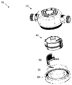
[0009] Fig. 1 is an exploded view of a plastic water meter 10 according to one
embodiment
of the present invention.
[0010] Fig. 2 is an exploded view of the housing assembly 20 shown in Fig. 1.
[0011] Fig. 3 is an exploded, cross-section view of a plastic water meter 10
according to one
embodiment of the invention.
-3-
CA 02650174 2009-01-19
DETAILED DESCRIPTION OF THE INVENTION
[0012] The present invention now will be described more fully hereinafter with
reference to
the accompanying drawings, in which some, but not all embodiments of the
inventions are
shown. Indeed, these inventions may be embodied in many different forms and
should not be
construed as limited to the embodiments set forth herein; rather, these
embodiments are provided
so that this disclosure will satisfy applicable legal requirements. Like
numbers refer to like
elements throughout.
[0013] Various embodiments of the present invention provide improved plastic
water meters
that address issues known in the art, some of which are discussed above. Fig.
1 illustrates a
plastic water meter 10 according to one embodiment of the present invention.
This embodiment
may include a water meter housing assembly 20 that may enclose a metering
device 40 and a
strainer 50. The metering device 40 and the strainer 50 may be positioned
inside the housing
assembly 20, and a bottom cover 60 and an o-ring 55 may enclose them within
the housing
assembly 20.
[0014] Referring to Figs. 2 and 3, the housing assembly 20 may include a top
cover 21 and
two connector assemblies 24A, B. Each connector assembly 24A, B may include a
plastic spud
insert 26A, B and a metal ring 25A, B, and one connector assembly may function
as an inlet
connector assembly 24A and the other connector assembly may function as an
outlet connector
assembly 24B. Additionally, the top cover 21 may include an integrated inlet
spud 23A and an
integrated outlet spud 23B. The top cover 21 and the two spud inserts 26A, B
may be made from
various types of plastic or high-strength polymer materials, including
styrene, polystyrene,
nylon, or the like. In a preferred embodiment, the top cover 21 and the two
spud inserts 26A, B
may be composed of glass reinforced thermoplastic. Factors that may be
considered when
selecting a material include working pressures of the meter, and working
temperature ranges.
[0015] The top cover 21 may be substantially cylindrical in shape with an
integrated top face
portion 22, although those skilled in the art will recognize that the top
cover 21 may take other
shapes. The bottom of the top cover 21 remains open, thus forming an aperture
that leads to the
interior cavity 31 of the top cover 21.
[0016] Proximate the bottom of the top cover 21 may be external threads 30,
which may
enable the bottom cover 60 to engage to the top cover 21. In use, the top
cover may flex
outwards because of pressure in the system thereby causing the internal
threads in the top cover
-4-
CA 02650174 2009-01-19
to be urged against the complementary threads on the bottom cover. In other
embodiments, the
top cover may include internal threads designed to engage external threads on
the bottom cover.
[0017] One advantage of the external bottom threads 30 provided in various
embodiments of
the present invention may be that external bottom threads 30 are easier to
manufacture than
internal bottom threads. As will be understood by those skilled in the art,
forming internal
threads requires an insert mold, while forming external threads does not. In
some cases, an
additional manufacturing step may be required to remove the internal thread
mold insert, which
may reduce the efficiency of the molding process.
[0018] In the illustrated embodiment, the top cover 21 may include an
integrated inlet spud
23A, through which water enters the interior cavity 31 defined by the top
cover 21, and an
integrated outlet spud 23B, through which water exits the top cover 21. The
inlet spud 23A and
outlet spud 23B may be in communication with the interior cavity 31 of the top
cover 21. Also,
the inlet spud 23A and the outlet spud 23B may be each designed to receive and
engage a portion
of the spud insert 26A, B.
[0019] Both the inlet spud 23A and the outlet spud 23B protrude substantially
perpendicularly from the exterior of the top cover 21, with the outlet spud
23B situated
approximately 180 degrees around the exterior of the top cover 21 from the
inlet spud 23A. As
will be understood by those of skill in the art, the inlet spud 23A and outlet
spud 23B may have a
relative orientation other than 180 degrees.
[0020] The spuds 23A, B may be substantially similar to each other and may
have a
substantially cylindrical in shape. Each spud 23A, B defines an axial bore
with a proximate
orifice that opens through the wall of the top cover 21 into the interior
cavity 31 of the top cover
21 and a distal orifice that opens away from the top cover 21. The proximate
orifice and distal
orifice of each spud 23A, B may be substantially circular in shape. In
alternative embodiments
of the present invention, each spud 23A, B, may not protrude from the exterior
of the top cover
21, but may instead be an orifice in the exterior of the top cover 21.
[0021] The bores defined by the inlet spud 23A and the outlet spud 23B may be
each sized to
receive a spud insert 26A, B respectively, and each spud insert 26A, B may
include an externally
threaded metal ring 25A, B. A purpose of the threaded metal rings 25A, B may
be to facilitate
connection of the water meter to a water system, which generally utilizes
metal threads for the
-5-
CA 02650174 2009-01-19
connection to the water meter. Each spud insert 26A, B may be substantially
cylindrical in shape
with a bore formed therein to allow the passage of water.
[0022] Each spud insert 26A, B may include a first end proximate to the top
cover 21 and a
second end distal the top cover 21. Proximate the second end of each spud
insert 26A, B may be
an annular lip portion or rim 29A, B that extends outwardly. Each threaded
metal ring 25A, B
may be positioned proximate the annular lip portion 29A, B on the spud insert
26A, B. A
purpose of the annular lip portion 29A, B may be to aid in positioning the
threaded metal ring
25A, B on the spud insert 26A, B and to discourage removal of the threaded
metal ring 25A, B
when the spud insert 26A, B may be engaged with the top cover 21, as will be
discussed in
greater detail later. Additionally, the spud insert 26A, B may include a
collar portion 28A, B that
may have a circumferential profile and may be positioned proximate to the lip
portion 29A, B.
The collar portion 28A, B may be shaped to engage a complementary shaped
profile of the inner
surface of the threaded metal ring 25A, B to discourage relative rotation
between the threaded
metal ring 25A, B and the spud insert 26A, B. In one embodiment, the
circumferential profile of
the collar portion 28A, B may define a shape having at least one linear
section or facet. In other
embodiments, the circumferential profile of the collar portion 28A, B may
define a shape having
a plurality of linear sections. In such embodiments, the circumferential
profile may take the
shape of, for example, a triangle, square, pentagon, hexagon, or octagon. In
even more
embodiments, the circumferential profile of the collar portion 28A, B may be
substantially oval.
In further embodiments, inner surface of the threaded metal ring 25A, B may
engage the collar
portion 28A, B by a key-fit arrangement.
[0023] Extending from the collar 28A, B of each spud insert 26A, B may be an
engagement
portion 27A, B. This engagement portion 27A, B may have a cylindrical shape
and may be sized
to be positioned within the axial bore of a spud 23A, B. The orifice proximate
the engagement
portion 27A, B of each spud insert 26A, B may be substantially circular in
shape and may be
substantially perpendicular to each cylindrically-shaped spud insert 26A, B.
In various
embodiments, the exterior diameter of the engagement portion 27A, B of each
spud insert 26A,
B may be substantially similar to the interior diameter of the axial bore of
each spud 23A, B.
Thus, the engagement portion 27A, B of each spud insert 26A, B fits snugly
into its associated
spud 23A, B. In some embodiments, there may be a mild interference fit. The
spud insert 26A,
B may be secured to the respective spud 23A, B using spin welding, solvent
welding, sonic
-6-
CA 02650174 2009-01-19
welding, or an adhesive. An advantage of this arrangement may be that the
metal threads do not
contact the water supply and therefore do not impact the zero lead content
requirements present
in many jurisdiction.
[0024] The threaded metal ring 25A, B may be made from various types of metals
and metal
alloys, including brass, bronze, brass or bronze derivatives, stainless steel,
or other similar metal
materials. In a preferred embodiment, the threaded metal ring 25A, B may be
made of bronze.
Factors that may be considered when selecting a material for the threaded
metal ring 25A, B
include material strength and corrosion resistance.
[0025] In alternative embodiments, the top cover 21 may include one spud or
may include
more than two spuds, in accordance with the present invention. In such
embodiments, each spud
would be similar in construction to the spuds disclosed above and would be
shaped to engage a
spud insert that may include a metal threaded ring, in accordance with the
above disclosure.
[0026] In various embodiments, the metering device 40 may be a nutating disk
displacement
flow meter, wobble plate meter, or other metering device known in the art. The
metering device
40 may contain an inlet through which water enters the metering device 40 and
an outlet through
which water exits the metering device 40. Referring to Fig. 3, the metering
device 40 may
contain a nutating disk 42 mounted on a sphere 44 that is "wobbled" by the
fluid flow where
each "wobble" represents a finite amount of fluid transferred. It should be
understood that other
types of metering devices may be used in connection with the present
invention.
[0027] The strainer 50 may be semi-cylindrical in shape and may be designed to
be situated
between the inlet spud of the top cover 21 and the inlet of the metering
device 40. The strainer
50 may be designed to strain foreign objects from the water before the water
enters the metering
device 40.
[0028] The metering device 40 and the strainer 50 may be positioned inside the
top cover 21
and the bottom cover 60 may enclose them within the top cover 21. The bottom
cover 60 may be
circular in shape and may contain a top face that may be configured to be
positioned proximate
to the top cover 21 and a bottom face that may be distal to the top cover 21.
The top face of the
bottom cover 60 may contain a substantially annular channel that may be shaped
and sized to
engage the bottom end of the top cover 21. In particular, the width of the
channel may be
substantially similar to thickness of the wall of the bottom end of the top
cover 21. The exterior
wall of the channel may include threads that are configured to engage the
external bottom
-7-
CA 02650174 2009-01-19
threads 30 of the top cover 21 to enclose the metering device 40 and the
strainer 50 within the
interior cavity 31 of the top cover 21.
[0029] The bottom cover 60 may be made from various types of plastic or high-
strength
polymer materials, including styrene, polystyrene, nylon, or the like. In a
preferred embodiment,
the bottom cover 60 may be composed of glass reinforced thermoplastic. Factors
that may be
considered when selecting a material include working pressures of the meter,
and working
temperature ranges.
[0030] The o-ring 55 may be positioned in the channel to provide a seal
between the top
cover 21 and the cover 60. In the illustrated embodiment, the cross section of
the o-ring is
circular; however, other o-ring profiles may be used in connection with
embodiments of the
present invention.
[0031] Many modifications and other embodiments of the inventions set forth
herein will
come to mind to one skilled in the art to which these inventions pertain
having the benefit of the
teachings presented in the foregoing descriptions and the associated drawings.
Therefore, it is to
be understood that the inventions are not to be limited to the specific
embodiments disclosed and
that modifications and other embodiments are intended to be included within
the scope of the
appended claims. Although specific terms are employed herein, they are used in
a generic and
descriptive sense only and not for purposes of limitation.
-8-