Note: Descriptions are shown in the official language in which they were submitted.
CA 02650654 2012-09-10
WO 2007/127447 PCT/US2007/010366
REINSTATEMENT OF AN EXISTING CONNECTION IN
A LINED CONDUIT
BACKGROUND OF THE INVENTION
10001 1 This invention relates to an apparatus and method for internally
reinstating a
connection in a lined conduit, and more particularly to the internal
reinstatement of a
service in a conduit that has an installed corporation stop.
[0002] A variety of circumstances exist in which it is desirable to form a
junction or
branch line from a main, fluid-carrying conduit. For instance, in the
municipal. area, it is
often necessary to install a branch line into a water main, gas main or sewer
main. A
similar need exists in other industries, such as in the chemical pipeline
industries.
[0003] In the municipal area, many water mains were constructed years ago and
the
wall structures are now badly eroded or collapsing. In order to repair such
damage, it has
been proposed to install a liner within these lines to provide a new water-
impervious wall
to the system. There are a wide variety of different methods available in the
art for
inserting liners within existing conduits. These lining methods include the
cured-in-
place, fold-and-form and diameter reduction methods, each of which inserts a
liner from
one end of the conduit to the other. However, the wall of the line is usually
not
continuous since branch lines and service connections intersect the main
conduit at
various entry ports to allow the free flow of fluid from the main to the
branch service line.
In the case of existing and newly formed entry ports, it is desirable to
utilize a corporation
stop at the junction to control the fluid on either a temporary or a permanent
basis.
[00041 It is desirable to reinstate the connection internally after the lining
operation.
To be successful, the reinstatement must form a seal between the reconnection
number
and the lining and between the reconnection number and the branch or service
connection.
CA 02650654 2012-09-10
WO 2007/127447 PCT/US2007/010366
[00051 In the case of service connections, there are a variety of corporation
stops in
the prior art. All suffer from some deficiency. Many of the prior art
assemblies are
complicated in design and are time consuming to install. Standardized
machinery has
been developed for installing corporation stops in conduits carrying fluid
under pressure,
such as the B-101 drilling and tapping machines manufactured by Mueller Co.
However,
this machinery is not well suited for use with a conduit that has been lined
or rehabilitated
with a synthetic liner.
[0006] A prior art corporation stop assembly that is specifically designed for
installation in a conduit lined with a synthetic liner from the outside is
disclosed in U.S.
Pat. No. 5,199,145 to McMillan et al. While entirely suitable, such method
requires
excavation of the buried conduit to install the connection externally. The
McMillan et al.
corporation stop has a flexible sleeve member and a threaded stem with an
enlarged head
portion, and is installed into the lined conduit by way of a clamp nut that
engages the
neck portion of the threaded stem for forcibly moving the lower end of the
sleeve member
over the head portion of the stem to expand the lower end of the sleeve member
inside the
conduit to form an internal seal with an opening in the conduit.
[0007) Another example of an external tap being installed from the outside of
the
conduit is disclosed in U.S. Patent No. 5,737,822 to Driver et al. They
disclose a
corporation stop assembly for use with standard tapping equipment including a
threaded
stem with an enlarged, conical head for forming a blind side seal. A standard
saddle
having a radially-inward tab is placed on the external sidewall of the conduit
about the
opening and receives the compression ring, the tab engaging the notch in th e
compression
ring. The stem, saddle member and compression ring engage each other to
prevent
relative rotation during installation.
[0008] While these devices allow for installation of a connection in a lined
conduit,
they require external access to the connection joint. Accordingly, it is
desirable to
provide an improved method and apparatus to reinstate a connection internally
to avoid
the need to excavate at each connection.
2
CA 02650654 2012-09-10
SUMMARY OF THE INVENTION
[0009] According to one aspect of the present invention, an assembly is
provided
for reinstating a connection in a conduit having an internal lining. The
assembly
comprises an elongated frame having a first end and a second end. A camera is
located at one end of the frame and a robot assembly is located at the other
end. A
motor is also mounted on the frame. A cylinder with a cartridge slide holding
a
plurality of T-nuts for installation into a connection in a conduit is coupled
to a
cartridge motor. The robot assembly includes a cylinder having an arm that can
be
rotated and extended and retracted selectively. A lift rack is mounted on the
arm
and a turntable including a drive element is mounted on the lift rack and
operatively
connected to the motor. The drive element can be selectively positioned to
engage
one of the plurality of T-nuts stored on the cartridge slide and position the
one
T-nut for installation into a connection in the conduit.
[0010] The assembly preferably includes a cutting element on the turntable for
cutting at least one opening in the liner for inserting the one T-nut. The
assembly preferably further includes a remote sensing mechanism mounted on the
frame and biased towards a conduit wall. The remote sensing mechanism is
preferably an eddy current detector.
BRIEF DESCRIPTION OF THE DRAWINGS
[0011] An embodiment of the invention will now be described by way of
example only with reference to the accompanying drawings in which:
[0012] FIG. I is a perspective view of a segment of a lined fluid-carrying
conduit having a corporation stop installed on the fluid carrying conduit as
arranged in accordance with the invention;
[0013] FIG. 2A is a partial cross-section view of the fluid-carrying conduit
showing the liner installed in the fluid-carrying conduit of FIG. 1, with a
protruding corporation stop;
[0014] FIG. 2B is another partial cross-section view of the fluid-carrying
conduit showing the liner installed in the fluid-carrying conduit of FIG. I,
with a
flush corporation stop;
[0015] FIG. 2C is another partial cross-section view of the fluid-carrying
conduit showing the liner installed in the fluid-carrying conduit of FIG. 1,
with a
corporation stop mounted within an external saddle attached to the outside
wall of
3
CA 02650654 2012-09-10
the conduit;
[0016] FIG. 3A is a perspective view of a hole saw with centering bit that is
used to form two concentric openings in the liner in accordance with the
invention;
[0017] FIG. 3B is a perspective view of a hole saw bit that is used to form
one
concentric opening in the synthetic liner in accordance with the invention;
[0018] FIG. 3C is a perspective view of a milling bit that is used to form one
concentric opening in the synthetic liner in accordance with the invention;
[0019] FIG. 3D is a perspective view of a milling bit with centering bit used
to form two concentric openings in the liner in accordance with the invention;
4
CA 02650654 2012-09-10
WO 2007/127447 PCT/US2007/010366
[0020] FIG. 3E is a perspective view of a heated hole cutting bit that is used
to form
one concentric opening in the synthetic liner in accordance with the
invention;
[00211 FIG. 3F is a perspective view of a heated hole cutting and centering
bit that is
used to-form-two concentric openings--in-the-synthetic-liner-in-accordance-
with-the--
invention;. .
[0022] FIG. 3G is a perspective view of a milling bit with a bearing end used
to
remove the protrusion of a corporation stop before liner insertion in
accordance with the
invention;
[0023] FIG. 4 is a perspective view of a self-aligning tap for forming an
internal
thread in the corporation. stop in accordance with the invention;
[00241 FIG. 5A is a perspective view of a self-tapping T-nut that is screwed
into the
corporation stop in accordance with the invention;
[0025] FIG. 5B is a perspective view of a threaded T-nut with straight thread
that is
screwed into the corporation stop in accordance with the invention;
[00261 FIG. 5C is a perspective view of a threaded T-nut with, tapered- thread
that is
screwed into the corporation stop in accordance with the invention;
[0027] FIG. 5D is a perspective view of a sealing gasket which is placed
around the
shaft of a T-nut and screwed into the corporation stop in -accordance with the
invention;
[00281 FIG. 5E is a perspective view of a T-nut assembly including a sealing
gasket
and sealing washer, which is screwed into the corporation stop in accordance
with the
invention.
[0029] FIG. 5F is a perspective view of a T-nut and sealing gasket, which is
screwed
into the corporation stop in accordance with the invention; and includes a
sealing washer
in accordance with the invention;
[0030] FIG. 5G is a cross-sectional view of the fluid-carrying conduit with
liner and
reinstated corporation stop in accordance with the invention;
[0031] FIG. 6 is a view similar to FIG. 2 showing a concentric opening in the
liner at
the start of forming a internally sealed connection between the corporation
stop and the
synthetic liner;
[0032] FIG. 7 is a view similar to FIG. 6 showing a T-nut and a sealing gasket
about
be inserted within the opening in the synthetic liner and corporation stop in
accordance
with the invention;
CA 02650654 2012-09-10
WO 2007/127447 PCT/US2007/010366
[0033] FIG. 8 is a view similar to FIG. 7 showing the installed internal tap
constructed
and arranged in accordance with the invention that achieves a seal between the
corporation stop and the synthetic liner,
[0034] - FIG .--g is-a-PersPective view-of a self--taFFn nut--with-a-drilling-
bit-on-the
il;T~ -
pilot end that is used to form the concentric opening in the liner in
accordance with
another embodiment of the invention;
[0035] FIG. 10 is a perspective view of a self-tapping T-nut with a punching
bit on the
pilot end that is used to form the concentric opening in the liner in
accordance with
further embodiment of the invention;
[0036] FIG. I 1 is a perspective view of a T-nut with a knurled body and an O-
ring seal
with an internal swage. nut that helps guide the T-nut in the inner diameter
of the
corporation stop in accordance with another embodiment of the invention;
[0037] FIG. 12 is a perspective view of a turntable having a removable hex, or
other
shape, drive in which the bits for making concentric openings in the synthetic
liner, for
milling the corporation stops, for tapping and for installing T-nuts in
accordance with the
invention;
100381 FIG. 13 is a perspective view of an automatic T-nut loader constructed
and
arranged in accordance with the invention;
[0039] FIG. 14 is an elevational view of an air motor for mounting hole
cutting
milling bits and remote sensing technology, such as an eddy current probe in a
lined
conduit;
[0040] FIG. 15 is a perspective view of cutting/milling apparatus of FIG. 14;
_ _tO041]_ FIG. 16 is an elevational view of an air motor utilized for
mounting cutting bits
on the loader of FIGS. 14 and 15;
[0042] FIG. 17 is perspective view of an assembly with loader constructed and
arranged in accordance with the invention;
[0043] FIG. 18 is a perspective view of the motor and cartridge loader section
of the
assembly of FIG. 17;
[0044] FIG. 19 is a perspective view of the turntable with a mounted T-nut and
robot
with lift of the tapping assembly of FIG. 17; and
[0045] FIG. 20 is a perspective view of the hex drive with ball detent of the
turntable
shown in FIG 19.
6
CA 02650654 2012-09-10
DESCRIPTION OF THE PREFERRED EMBODIMENTS
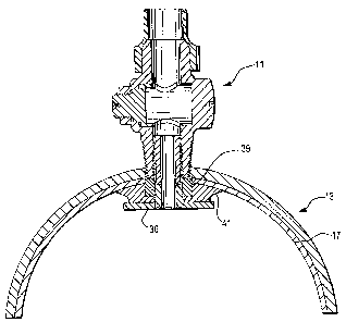
[0046] FIG. I shows a corporation stop 1l installed on a longitudinally
extending host
conduit 13. Host conduit or pipe 13 could be, for instance a water main, gas
main, sewer
pipe, or the like. In this instance, conduit 13 is made of steel and has a
generally
cylindrical interior sidewall 15 which has been lined with a synthetic liner
17 formed
from a cured in place liner or polyolefin, e.g. polyethylene or other similar
synthetic
lining system.
[0047] A well-known process for rehabilitation of existing conduits generally
utilizing a
flexible liner to be cured in place is the Insituform Process described in
U.S. Pat. Nos.
4,009,063 and 4,064,211. Another rehabilitation process known as the NuPipe
Process
is described in U.S. Pat. No. 4,867,921 and No. 5,255,624. In this latter
process a
substantially rigid replacement pipe is installed in a flattened and folded
shape, heated
and expanded to the shape of the original conduit. Another process for lining
conduits
familiar to those skilled in the art is diameter reduction, which is described
in U.S.
Pat. No. 4,923,663, issued to McMillan. Another pipe lining and process is
discussed in
U.S. Patent No. 5,934,332 to Rodriguez et al. This later pipe lining is used
in the
examples shown herein in the drawings.
[0048] FIG. 2A shows a partial cross-section view of conduit 13 showing liner
17
installed in conduit 13 with corporation stop 11 that is not entirely
connected to conduit
13. Generally, corporation stops usually protrudes into the conduit as shown
here.
Corporation stop II protrudes into conduit 13 and thus makes a depression in
liner 17.
This depression may be found by inserting a robot into the conduit that has a
camera for
detecting the locations of the depressions. Once a depression is found, a
cutting tool bit
may be used by the same robot to form at least one opening in liner 17 at the
location of
corporation stop 11.
[0049] FIG. 2B shows a partial cross-sectional view of conduit 13 showing
liner 17
installed in conduit 13 with corporation stop 11 that is not entirely
connected to conduit 13 and is
not protruding into the conduit 13.
7
CA 02650654 2012-09-10
WO 2007/127447 PCT/US200 7/010366
[0050] FIG. 2C shows a partial cross-sectional view of conduit 13 showing
liner 17
installed in conduit 13 with corporation stop 11 that is not entirely
connected to conduit
13, is not protruding into the conduit 13 and is attached to an external
saddle which is
--- -attached--to-the-external-wall-of-the-conduit-.13_-Without-a_protrusionof
corporationstop
II into conduit 13, there is no visually noticeable depression in liner 17, as
well as
removing any temporary inserted fittings. Without visual detection, another
method of
detection using remote sensoring technology, such as eddy current technology,
mounted
on a robot, can be used for locating the corporation stop. Once a corporation
stop is
found, a cutting tool bit may be used by the same robot to form at least one
concentric
opening in liner 17.
[0051) FIGS. 3A and 3B show respectively a hole saw bit 21 with and without a
centering bit 22 and a saw 26 at one end and a hex end 23 at the other end.
Centering bit
22 is used to drill a first opening 19 in liner 17 where a outside shoulder 24
of centering
bit 22 is sized to the inside diameter of the corporation stop 11. Saw 26 is
used to drill a
second concentric opening 27 in liner 17 with saw 26 sized to the outside
diameter of
corporation stop 11. Note that first opening 19 and second concentric opening
27 are
drilled around the same time. With no centering bit 22, one larger opening 27
in liner 17
is formed where saw 26 is sized to the outside diameter of corporation stop
11. Hex end
23 of hole saw bit 21 fits into a turntable 61 (shown in FIG. 12) and is
secured with a
snap ring groove 28. Turntable 61 drives hole saw bit 23. Turntable 61 mounts
onto a
standard lateral reinstatement cutter 63 which is mounted onto a modified
robot. An air
motor 71 mounted on a standard lateral reinstatement cutter 63 may act as an
alternative
method for mounting of cutting devices as shown in FIG. 12 and FIG 14.
[00521 FIGS. 3C and 3D shows milling bit 20 with and without a centering bit
25 at
one end. Centering bit 25 is used to drill a first opening 19 in liner 17
where outside
shoulder 24 of centering bit 25 is sized to the inside diameter of corporation
stop 11.
Milling bit 20 is used to mill a second concentric opening 27 in liner 17
where milling bit
20 is sized to the outside diameter of corporation stop 11. Note that first
opening 19 and
second concentric opening 27 are performed around the same time. With no
centering bit
25, one opening 27 in liner 17 is formed where milling bit 20 is sized to the
outside
diameter of corporation stop 11. Air motor 71 mounted on a standard lateral
reinstatement cutter 63 acts as the method for mounting of cutting devices as
shown in
8
CA 02650654 2012-09-10
WO 2007/127447 PCT[US2007/010366
FIG. 14. Alternatively, a hex end of milling bit 20 fits into turntable 61 and
is secured
with a snap ring groove 28. Turntable 61 drives the milling bit 23. Turntable
61 mounts
onto standard lateral reinstatement cutter 63 which is mounted onto a modified
robot.
[00531 ----FIGS. 31 -and FL respestivel-y-show--a-heated-hole-cutting-bit-2-9-
with--and
without a centering bit 31 at one end and a hex end 23 at the other end.
Centering bit 29
is used to bum a first opening 19 in liner 17 where outside shoulder 24 of
centering bit 22
is sized to the inside diameter of corporation stop 11. A heated hole cut ter
29 is used to
burn a second concentric opening 27 in liner 17 where heated cutter 29 is
sized to the
outside diameter of corporation stop 11. First opening 19 and second
concentric opening
27 are performed around the same time. With no centering bit 30, one opening
27 in liner
17 is formed where heated. hole cutter 26 is sized to the outside diameter of
corporation
stop 11. Hex end 23 of heated hole cutter bit 21 fits into turntable 61 and is
secured with
a snap ring groove 28. Turntable 61 drives the heated hole cutter bit 23.
Turntable 61
mounts onto a standard lateral reinstatement cutter 63 which is mounted onto a
modified
robot as shown in FIG. 12.
[0054J FIG. 3G shows a perspective view of a milling bit 20' with a bearing
end 45
used to remove the protrusion of corporation stop 1 I before liner insertion.
Referring
now to FIG. 4, a tap 31 having a self-aligning pilot end 32 and a hex end 33
is shown.
Hex end 33 of tap 31 fits into turntable 61 (See FIG. 12) and is secured with
a snap ring
groove 34. Tap 31 is used to thread the. inner bore of corporation stop 11.
The threads
formed are left hand threads so as not to loosen corporation stop 11 during
the tapping
with tap 31 or installation of T-nut 36. Pilot end 32 is sized to the inside
diameter of the
corporation stop 11- and the end of the pilot end 32 is sharpened to remove
material or
scale if needed. Tap threading is not applicable if a self-tapping T-nut 36 is
used.
[00553 FIG. 5A shows a self-tapping T-nut 36 that is to be screwed into
corporation
stop 11. Self-tapping T-nut 36 has a tubular or pilot end 37 and a hex end 38.
Pilot end
37 is sized to the inside diameter of the corporation stop 11 to guide it
straight and to
prevent cross threading. Hex end 38 has a broached hex opening 39 in the
center. When
using self-tapping T-nut 36, corporation stop 11 does not need to be threaded
because
self-tapping T-nut 36 makes its own thread. Preferably, the thread is coarse
to prevent
stripping around and the thread design is about 10 degrees and the thread
profile is
narrow such that self-tapping may be achieved in corporation stop 11 with
unknown or
9
CA 02650654 2012-09-10
WO 2007/127447 PCT!US2007/010366
varying internal bore diameter. Threads are left hand threads so as not to
loosen
corporation stop 11 during installation of self-tapping T-nut 36. Self-tapping
T-nut 36
can be driven into corporation stop 11 by the outside perimeter of hex end 38
or can be
---riven-into--corpor-ation-stop--l-l-by-a-bc-oached-hex-opening-
39_in_the_inneL_diameter of hex
end 38. T-nut 36 is removable for either robotically from inside the liner 17
or from
outside by access thru the corporation stop 11 inner bore. T-nut 36 can be
made with no
flow-thru in the case where a blind connection is required (e.g., abandoned
connections).
[00561 FIG. 5B shows a standard straight threaded (not self-tapping) T-nut 36'
that is
to be screwed into corporation stop 11. FIG. 5C shows a standard tapered T-nut
36" that
is to be screwed into corporation stop 11. The threaded T-nuts have a.pilot
end 37 and a
hex end 38. Pilot end 37 is sized to the inside diameter of corporation stop I
1 to guide it
straight and to prevent cross threading. Hex end 38 has a broached hex opening
39 in the
center. When using T-nut 36, corporation stop I1 must be previously threaded
with tap
31. Threads are left hand threads so as not to loosen corporation stop I 1
during tapping
with tap 31 or installation of T-nut 36. T-nut 36-can be driven into
corporation stop I I by
the outside perimeter of hex end 38 or can be driven into corporation stop l l
by a
broached hex opening 39 in the inner diameter of hex end 38. T-nut 36 is
removable for
repair either robotically from inside the liner 17 or from outside by access
thru the
corporation stop 1 I inner bore. T-nut 36 can be made with no flow-thru in the
case where
a blind connection is required (e.g., abandoned connections).
[00571 FIG. 5D is a perspective view of a sealing gasket 41 which is placed
around
the shaft of a T-nut and screwed into the corporation stop 11. FIG. 5E shows a
perspective view of a -T-nut assembly 40 with a sealing gasket 41 and a rigid
sealing
washer 35 placed around pilot end 37 of T-nut 36 and screwed into corporation
stop 11.
Sealing gasket 41 can be any suitable gasket material acceptable for the fluid
carried in
the conduit, such a rubber or a compressible synthetic material. Preferably,
gasket 41 is
an EPDM rubber or other suitable elastomeric sealing material. FIG. 5F is a
perspective
view of a T-nut assembly with sealing gasket 41 and sealing washer 39 and FIG.
5G is a
cross-section of a lined conduit with the T-nut assembly installed in
corporation stop 11.
[00581 FIGS. 6-8 illustrate the installation of a sealed connection in
corporation stop
11 within an opening provided in liner 17. Liner 17 is impermeable to water
and air.
CA 02650654 2012-09-10
WO 2007/127447 PCT[US2007/010366
[0059] FIG. 6 shows an opening 14 in liner 17 at the start of forming an
internally
sealed connection between corporation stop 11 and liner 17. FIG. 7 illustrates
self-
tapping T-nut 36 and seating gasket 41, with or without sealing washer 35,
about be
~nser-ted-withi-n-open-ing44-in-liner-l7-and-cot~oration-Stop 11 Seating
gastcet 4 Land hPx
end 38 of T-nut 36 pushes against liner 17 and makes a sealed connection at
liner 17 to
the conduit as -shown in FIG. 8. Here, the internal connection fully forms an
internally
sealed connection between corporation stop i l and liner 17. Generally, once
self-tapping
T-nut 36 is installed in liner 17 it makes a mechanical locking point and
holds liner 17 in
place.
-(0060}- - In the case where the T-nut used is not self tapping, tap 31 is
used to thread
corporation stop 11 as shown in FIG. 4. Pilot end 32 is sized to the inside
diameter of the
corporation stop I 1 and the end of pilot end 32 is sharpened to remove
material or scale if
needed. After corporation stop 11 is threaded, the installation of T-nut 36 in
corporation
stop I 1 within an opening provided in liner 17 can proceed as shown in FIGS.
6-8. T-nut
36 is screwed with a sealing gasket 41 facing liner 17nto corporation stop
forming an
internally sealed connection between corporation stop 11 and liner 17.
[0061] In FIG. 9, another type of T-nut is shown called a drill bit self-
tapping T-nut
46 that is to be screwed into corporation stop 11. Self-tapping T-nut 46 has a
drill bit
pilot end 47 and a hex end 48. Drill bit pilot end 47 is sized to the inside
diameter of
corporation stop I1 to guide it straight and. drills an opening directly into
liner 17 to
prevent cross threading. In addition, drill bit pilot end 47 threads
corporation stop l 1 and
seals against liner 17. Hex end 48 has a broached hex 49 (not shown) in the
center.
Preferably, the thread is coarse to prevent stripping around and the thread
design is about
degrees. Self-tapping T-nut 46 can be driven into corporation stop 11 by the
outside
perimeter of hex end 48 or can be driven into corporation stop 1 I by a
broached hex 49 in
the inner diameter of hex end 48.
[0062] Another type of T-nut is shown called a punch bit self-tapping T-nut 56
that is
to be screwed into the corporation stop 1 I is shown in FIG. 10. Self-tapping
T-nut 56 has
a punch bit pilot end 57 and a hex end 58. Punch bit pilot end 57 is sized to
the inside
diameter of the corporation stop l I to guide it straight and punches an
opening directly
into liner 17 to prevent cross threading. In addition, punch bit pilot end 57
threads
corporation stop 11 and seals against liner 17. Hex end 58 has a broached hex
59 (not
11
CA 02650654 2012-09-10
WO 2007/127447 PCT/US2007/010366
shown) in the center. Preferably, the thread is coarse to prevent stripping
around and the
thread design is about 10 degrees. Self-tapping T-nut 56 can be driven into
corporation
stop I I by the outside perimeter of hex end 58 or can be driven into
corporation stop I I
----- -by--a broached-hex- 59--in -the-inner-diameter hex-end 58
[00631 When using drill bit self-tapping T-nut 46 or punch bit self-tapping T-
nut 56,
the initial hole in liner 17 is form by the drill bit T-nut 46 or punch bit T-
nut 56 while
threading the corporation stop and sealing the liner simultaneously. In this
case a sealing
washer 39 or 139 shown in FIGS. 5F and 19 is used with T-nut 36 as shown in
FIGS. 5F
and 5G. When corporation stop is threaded, sealing washer 39 or 139 is not
essential as
the threads on T-nut 37 can be wrapped with Teflon tape to form a seal.
[00641 In FIG. 11 another of type of T-nut is shown called a compression T-nut
66
that is to be placed into corporation stop 11. Here, compression T-nut 66 has
a knurled
body 70, an O-ring seal. 72 and an internal swage nut 73 (not shown) that
swages the body
of compression self-tapping T-nut 66 against the inner diameter of corporation
stop 11. A
threaded rod or bolt 74 is inserted into compression T-nut 66 before
installation and is
drawn tight causing the swage nut 73 to swage the body of compression fit T-
nut 66
outward and is swaged into place. Threaded rod 74 is then removed and the
robot is
reloaded for another placement of the next compression fit T-nut 66.
[00651 In all of the different T-nuts shown, a sealing gasket 41 preferably is
used for
sealing liner 17 against conduit 11, with or without sealing washer 39.
[0066] FIG. 12 shows turntable 61 that has hex drive 62 that is removable.
Turntable
61 mounts onto the standard lateral reinstatement cutter 63 (not shown).
Turntable 61 is
used to hold and drive Tap 31, cutting bits 21, a socket to drive the T-nut
from the outside
hex and hex drive 62 to drive the inner diameter of the hex, or other shape,
of the T-nut
with a ball detent 64 to hold the T-nut in place while moving down the pipe
and to
prevent T-nut slip out when handling the T-nut with automatic loading
mechanisms (FIG
13). Turntable 61 is powered by a motor located on the skid carrying the
standard lateral
reinstatement cutter robot 63. The motor is mounted on a sliding skid that is
able to travel
axially as the cutter robot extends and retracts axially within the vicinity
of the
corporation stop 11. Air motor 71 mounted on a standard lateral reinstatement
cutter 63
may act as an alternative method for mounting of cutting devices.
12
CA 02650654 2012-09-10
WO 2007/127447 PCTIUS2007/010366
[00671 A robot assembly 101 with a camera and cutting bit is sent into conduit
13 to
find protrusions to determine location of corporation stops 11 visually. Once
the robot
finds corporation stop 11, it is then used to form one or more openings in
liner 17. In
fill
,
ive-materials,
an eddy 111, it. probe 72
which the corporation stops 11 or -host conduits 13 are made from. Probe 72
may be
mounted onto the turntable with the cutting bit installed to locate
corporation stop 11 in
case where the protrusions of corporation stops 11 are not visible or when
corporation
stops I 1 have been intentionally milled flush with the internal wall of
conduit 13 prior to
lining. When probe 72 locates a brass corporation stop 11, a signal is sent to
the operator
identifying the center of corporation stop 11. At this time, turntable 61 or
air motor 71
may be rotated to a position allowing the cutting bit to form one or more
openings in
liner 17. Once the opening is cut in liner 17, another robot is inserted into
the conduit 13
with a self-tapping T-nut 46 to install self-tapping T-nut 46 and a sealing
gasket, or in the
instance where corporation stop 11 is already threaded, the T-nut installed is
not self-
tapping.
[0068] Eddy current probe 72 is mounted with a spring in a cylindrical housing
73. In
this manner probe 72 can ride along the surface of liner 17 and provide a
strong signal to
the operator where the center of corporation stop I 1 is located. In addition
to an eddy
current probe, connections can be located utilizing ultrasound, penetrating
radar, x-rays,
galvametric current differentiation, sonar, and the like.
[00693 FIG. 13 shows an automatic loader to hold additional T-nuts. This
avoids the
need to pull the robot out of the pipe after a reinstatement and insert a new
T-nut and then
reposition it in the pipe to install another T-nut. To do this would be costly
from a time
point of view.
[00701 An air cylinder 75 is mounted on one leg or more of a skid that pushes
a
"slide" that feeds the holster of sealing nuts to where the robot can maneuver
and pick up
one of the T-nuts. Once a T-nut is removed from the holster, the air cylinder
retracts the
slide to keep it out of the way of the reinstatement and sealing operation.
The slide and
skid allow for more than the one nut as depicted now in FIG. 13 and is shown
in FIGS. 17
and 18.
[00711 FIG. 14 shows an air motor 71 that mounts onto a standard lateral
reinstatement cutter 63 (not shown). Air motor 71 is used to hold and drive
cutting bits
13
CA 02650654 2012-09-10
WO 2007/127447 PCT/US2007/010366
21. Air motor 71 may include self-centering spring mechanism that allows the
cutting
bits to self align in the axial direction of conduit 13. Air motor 71 may also
include
remote sensing technology, such as eddy current probe 72. Sensing probes may
be
mountc-d M- -al-low-intimate-eont e1- wit-liner-l -While also
allowing radial movement of the cutting bits when making concentric openings
in liner
17. This is shown in a perspective view of air motor and sensing apparatus in
FIG. 15.
FIG. 16 is an elevational view of air motor 71 utilized for mounting cutting
bits 21
depicted in FIGS. 14 and 15.
[0072] There are various ways to carry the sealing nut on the robot. For
example, the
nut may rest in a hexagonal socket. This may tend to be a loose fit and can
"wobble" out
of the socket. The robot of FIG. 13 for picking up a nut out of the loader
holster utilizes a
hexagonal driver stem. which is mounted in the turntable of the robot. This
driver stem
include a ball detent and is inserted into the hexagonal bore of the sealing
nut. The driver
stem has a ball detent on the side, which prevents the nut from sliding off
the driver stem
and to prevent T-nut slip out when handling the T-nut with automatic loading
mechanisms (FIG. 13). A improved loader causing plurality of T-nuts is shown
in the
sealing assembly of FIGS. 17-20.
[0073] Referring now to FIGS 17-20, an internal reinstatement and sealing
assembly
101 constructed and arranged in accordance with the invention is shown.
Sealing
.assembly 101 includes a frame in the form of a sled 102 with a pair of
runners 103 and
104. A camera 106 is located at one end of frame 102 and a motor subassembly
shown
generally at 107 includes an electric motor 108 and a loader 109 is mounted
inward of
camera 106. Loader 109 includes an air cylinder 11 l with a cartridge slide
112 that is
coupled to the piston in air cylinder 111. Cartridge slide 112 rides in a
groove 105 in sled
102 as shown in FIG. 19 and carries a plurality of T-nut fittings 131.
Cartridge slide 112
extends from air cylinder 111 to position a T-nut filling for loading as
described below.
[0074] Assembly 101 includes a robot section 116 at the opposite end of frame
102.
Robot section 116 is an elongated rigid electrically controlled cylinder 117
having an
extension arm 119 that extends from cylinder 117 which can be extended and
retracted
selectively. A rotating cylinder 118 which can be rotated selectively
clockwise or
counterclockwise is mounted to extension arm 119 with a lift rack 120 secured
to rotating
14
CA 02650654 2012-09-10
WO 2007/127447 PCT[US2007/010366
cylinder 118. A turntable 121 with a hex drive 122 is operatively connected to
motor 108
by a driveshaft 110 and a first universal joint 124 and a second universal
joint 126.
[0075] By providing these various elements such as rotating cylinder 118,
extension
arras cylinder 1 19 and lift rank 120 T_nut 131 ran he successfully installed
into the bore
of an existing corporation stop in the lined conduit. As described earlier and
as shown in
FIGS. 19 and 20, T-nut 131 with a sealing gasket 132 has a hexagonal base 133.
In this
case, base 133 is hexagonal which allows installation utilizing a turntable
having a
hexagonal main cavity for turning T-nut 131 during sealing and/or
installation.
[00761 In the embodiment illustrated in FIGS 17-20, T-nut 131 includes a
hexagonal
internal bore 137 as shown in FIG. 20. Hex drive 122 includes a ball detent
138 for
.securing T-nut 131 to hex drive 122 during pick up and installation. A
substantially rigid
sealing washer 139 is installed around self-threading portion 134 of T-nut 131
and within
the center of compressible sealing donut 132, to ensure a seal with an
existing corporation
stop in the conduit. Sealing washer 139 is formed of a substantially rigid
engineering
plastic, such as nylon, LDPE, polyester, polyacetal, PTFE-and the like to
assist in the seal
between the base of T-nut 131 and the corporation stop and the lined conduit
wall.
[0077] T-nut 131 includes a- cylindrical self threading portion 134 with a
pilot end
136. Self threading portion 134 includes a coarse thread to prevent stripping
or coarse
threading set at approximately 10 in order to accommodate for variances in
water
corporation diameters. This also reduces the amount of torque required'to
thread T-nut
131.
[0078] Referring again to FIGS. 17 and 18, and 19 and 20, the detail of
cartridge slide
112 with multiple brackets 113 is shown in detail. Here, self threading
portion 134 of T-
nut 131 is mounted in bracket 113 with hex bore 137 facing the center of the
conduit. In
this case, once an internal reinstatement has been completed and turntable 121
is
positioned over cartridge slide 112 that is extended from air cylinder III so
that
turntable 121 can be lowered to allow hex drive 122 to enter and engage
internal bore 137
of T-nut 131. By rotating rotating cylinder 118 and turntable 121 in a
clockwise
direction, T-nut 131 is removed from bracket 113 and is ready for installation
into the
next corporation stop to be reinstated. Camera 141 and camera mounting bracket
142 aid
in the visual location of T-nut 131 in bracket 113.
CA 02650654 2012-09-10
[0079] By providing internal tapping assembly 101 with cartridge slide 112
holding a
plurality of T-nuts 131, several internal taps can be completed without the
necessity to remove
internal tapping assembly 101 from the line conduit in order to reload
turntable 121.
[0080] Loader section 109 includes a camera 141 to facilitate positioning and
providing information to an operator as T-nut 131 is positioned and installed.
Motor 108
is a variable speed motor that allows appropriate speed for installing T-nuts
131 into the
existing corporation stops. Motor 108 generally is driven electrically. While
internal
reinstatement and sealing assembly 101 is shown with rigid sled 102, it is
contemplated
within the scope of the invention to utilize any robot positioning device such
as tractors
and/or wheels. At time installation of a T-nut may restrict flow to the
connection. In this
case the bore of the connection or corporate stop can be enlarged and a larger
diameter T-
nut with larger bore can be installed to restore full fluid flow.
[0081] It can readily be seen that the process in accordance with the
invention readily
allows one to conveniently install an internal tap to connect and seal the
corporation stop
and synthetic liner.
16