Note: Descriptions are shown in the official language in which they were submitted.
CA 02650713 2012-09-10
1
A METHOD AND APPARATUS FOR TOMOGRAPHIC MULTIPHASE
FLOW MEASUREMENTS
The present invention relates to a method and flow meter for determining the
composition and flow rates
of individual components of a multiphase fluid.
The problem of how to meter oil-water-gas mixtures has been of interest to the
petroleum industry since
the early 1980s. Since then considerable research has been conducted into the
development of a three-
phase flow meter suitable for use in an industrial environment.
There are several techniques and known instruments for measuring multiphase
flow, as will be further
described below. Such instruments need to be reasonably accurate (typiaalty
better than 5 % of rate for
each phase), non-intrusive, reliable, flow regime independent and provide
accurate measurements over the
full component fraction range. In spite of the large number of solutions that
have been proposed in recent
years, no commercially available three phase flow meter yet meets all these
requirements. In addition to
stringent measurement requirements, the instrument needs to perform reliable
in a harsh and corrosive
environment such as several thousand meters below the sea surface. Inside the
pipe, the flowing
multiphase fluid may be traveling at a speed of 1-50 m/s with pressures in
excess of 1000 bars and
temperatures above 200 C. Sand is often also present and can damage the
interior of the instrument.
Multiphase flow in the oil & gas industry is commonly defined as a mixture of
liquids and gas where the
amount of free gas, also denoted GVF, is less than 90% of the volume of the
pipe. For GVFs in the range
90% - 99.99% , the multiphase flow is often referred to as a wet gas. In many
cases the producing wells
are defined as multiphase wells in the early production stage and may develop
into wetgas wells as the oil
is drained from the reservoir and more of the gas cap is produced. For
clarification purposes, multiphase
flow in the context of this patent application covers the full component
fraction range and hence includes
both wetgas and multiphase flow conditions.
The output of an oil/gas reservoir may vary greatly, depending on the location
and age of the
well. In addition to the oil and gas components, water, sand and wax may also
be present in the
produced well stream. Since the location and output of a well may vary so
widely, the systems that have
been designed to collect and process this output also vary considerably. The
initial target of the oil
industry to develop a universal multiphase flow meter to replace the
traditional separation/single phase
metering solution currently used, the fiscal monitoring of a well's output,
have yet to be realised.
Multiphase flow meters are increasingly used for well testing and allocation
measurement.
CA 02650713 2008-10-28
WO 2007/129897 PCT/N02006/000486
2
In order to optimise the production and life of an oil/gas field, operators
need to be able to regularly
monitor the output of each well in the field. The conventional way of doing
this is to use a test separator.
Test separators are expensive, occupy valuable space on a production platform,
and require a long time to
monitor each well because of the stabilised flow conditions required. In
addition, test separators are only
moderately accurate (typically 5 to 10 % of each phase flow rate) and cannot
be used for continuous
well monitoring. A three-phase flow meter could be used in the first instance
instead of a test separator
and in the long term as a permanent installation on each well. Such an
arrangement would save the loss in
production normally associated with well testing. Such loss is estimated to be
approximately 2% for a
typical offshore installation. Allocation metering is needed when a common
pipeline is used to transport
the output from a number of wells owned by different companies to a processing
facility. This is currently
achieved by passing the output of each well through a test separator before
entering the common pipeline.
However, in addition to the disadvantages of the test separator described
above, dedicated test pipelines to
each well are also required. A permanently installed three-phase flow meter
would offer significant
advantages for allocation metering.
According to a group of major oil companies, the accuracy requirements for a
multiphase meter within a
gas volume fraction range of 0-99% and water cut range of 0-90%, is 5-10%
relative error on the liquid
and gas flow rate and water cut measurement error within 2% abs. More accurate
measurements were
required for production allocation applications. Commercial three-phase flow
meters are now generally
capable of measuring individual phase fraction's flow rate to an uncertainty
of less than 10% over a
reasonably wide range of flow rates and phase fractions. There are two areas
of operation which need
further investigation if flow rate uncertainty is to be reduced still further
using current combinational
measurement techniques: flow regime dependency and individual phase velocity
measurement.
Some examples of commercially available non-intrusive multiphase meters, such
as those known from
NO 304333, NO 304332, US 5,103,181, WO 00/45133 (figure 5) and US 6,097,786,
measure the cross
sectional composition and velocity of the phases to obtain flow rates. In
order to provide accurate
measurements, a homogeneous mixture in the cross section of the pipe is
required. Effects due to
inhomogenity in the longitudinal direction of the pipe is normally minimised
by fast sampling of the
cross-sectional composition. Multiphase meters are normally not mounted in a
horizontal position due to
the presence of laminar flow, where water is in the bottom of the pipe and gas
at the top, which would
distort the measurement. Consequently, to achieve homogeneous mixture in the
cross section of the pipe
of a multiphase meter, it is common practice to install the multiphase meters
in such a way that the flow is
flowing in an upward or downward direction. Laminar flow may then be avoided.
However, when a
multiphase mixture containing gas and liquid(s) are flowing in a vertical
direction, annular gas
concentration often occurs. Annular gas concentration means that there is a
higher percentage of gas
(GVF) in the center of the pipe compared to the GVF at the pipe wall. The gas
concentration may be
CA 02650713 2008-10-28
WO 2007/129897 PCT/N02006/000486
3
symmetrical or un-symmetrical depending on the particular installation.
Symmetrical means that the GVF
is constant along the circumference of any circle with its origin in the
center of the pipe and a radius in
between the center of the pipe and the pipe wall. Annular gas concentration
flow distorts the
measurement in a similar manner as laminar flow in a horizontal installation.
In horizontal pipes pure
annular flow where all the gas is in the middle of the pipe would normally
only occur at higher gas
fractions. However, when the flow is flowing in vertical pipes, severe
concentration of gas in the middle
of the pipe has been experienced even at medium flow rates (a few m/s) and gas
fractions as low as 10%.
Even a concentration of the gas in the middle of the pipe at lower gas
fractions would introduce severe
measurement errors. In practice, the liquid is rarely completely free of gas.
NO 304333, US 5,103,181, US 6,097,786 and US 5,135,684 uses a nuclear
densitometer. When a nuclear
densitometer is used to measure the density, it is not possible to obtain fall
coverage of the cross section of
the pipe. Hence, in order to obtain accurate measurements, it relies on a
homogeneous mixture in the cross
section. Typical commercial available nuclear detectors for density
measurement, based on the Caesium
662 keV peak, has a circular area with a radius of 2" and lower. For dual
energy systems (x-ray and y-ray )
as described in US 5,135,684 and US 6,097,786, the area is normally even
smaller due to the need for a
composite window in the pipe in order to allow radiation from the low energy x-
ray radiation to go
through the pipe. The cover area in a 2" pipe with a typical commercially
available y-ray densitometer is
typically 70-80 % of the total cross sectional area of the pipe. However, when
used in a 6" pipe, it is
difficult to achieve more than 30% coverage of the cross section of the pipe.
One way to increase the
coverage is to place the density measurement inside a venturi passage as in US
5,135,684. However,
placing the nuclear density measurement inside a venturi passage also
increases the amount of annular
flow in the measurement section. When the source and detector is placed in the
middle of the pipe, a too
low density will be measured at annular flow. The error in the measurement
will increase as the area of the
pipe is increased. One way to compensate for this effect is to place the
densitometer off-centre. However,
the measurement errors due to annular gas concentration in the middle of the
pipe would still be
significant.
Yet another way to minimise the effect of annular flow is to use a mixing
device. US Re. 36,597 describes
a method where a positive displacement meter is used to both measure the total
flow rate and homogenise
the multiphase mixture in advance of the composition measurement. Annular flow
is then minimised;
however, the multiphase meter becomes highly intrusive and fragile since it
depends on a mechanical
restricting or rotating device located in the multiphase stream. The
repeatability of the measurement over
time would also be vulnerable to sand erosion. Another way to reduce the
presence of annular flow is to
use a mixer. US 5,135,684 refer to a method where a hold up-tank is used to
homogenise the multiphase
flow. However, the structure is highly intrusive, thus creating a pressure
drop and hence limiting the
production capabilities from the wells. The performance of the mixer would
also be dependent on the flow
CA 02650713 2008-10-28
WO 2007/129897 PCT/N02006/000486
4
rate and pattern such as length of gas and liquid slugs and could therefore
limit the operational envelope of
such a multiphase meter. Another method based on mixing of the multiphase flow
is described in US
6,272,934.
Yet another way to reduce the effect of annular flow is to perform the
composition measurement at the
cross section of an annular venturi is shown in W000/45133, figure 1. However,
this method is also
intrusive and the repeatability of the measurement over time would also be
vulnerable to sand erosion.
It is also well known that the composition of the multiphase mixture can be
measured based on a
measurement of the cut-off frequency of the pipe. Examples of such devices are
found in US 4423623, US
5455516 ,US 5331284, US 6614238, US 6109097 and US 5351521 describing methods
for determining
the composition of a multiphase mixture based on a measurement of the cut-off
frequency of a pipe based
on loss or phase measurements at a varying frequency. However, all these
methods are greatly influenced
by annular gas concentration and would not provide the required measurement
accuracy under such
conditions.
Tomographic techniques for measurements of multiphase flow are also well
known. Examples of such
devices are found in US 5485743, US 5130661, US 68 57323, US 6940286 and US
5793216. However all
these tomographic techniques require complex sensors and sophisticated
measurement algorithms for
deriving the composition and flow rates of the multiphase fluid and are
therefore difficult to realize in an
harsh industrial environment such as pipes with oil, gas and water. The
sensors are normally located
around the entire circumference of the pipe for the purpose of obtaining a
detailed image of the multiphase
distribution within the pipe. The complexity and rapid changes of multiphase
flow combined with the
complexity of the measurement algorithms involved in a full-blown tomographic
system may also easily
introduce instability in the calculation routines resulting in large errors in
the final calculations. It is also
time consuming to develop models for such a system making them difficult to
scale for different pipe
diameters. Furthermore, such systems are also time consuming to configure and
calibrate and not well
suited for industrial production.
WO 2005/067142 describes a multiphase flow meter based on a simplified
tomographic technique for
determination of the composition and flow rates. The method relies on annular
gas concentration in a
sensor element installed in a vertical upward flow direction. Based on
measurements performed in
multiple directions of the pipe, the degree of annular gas concentration is
determined and used in order to
determine fractions and flow rates of the components of the multiphase fluid.
However, the method relies
on symmetrical annular gas concentration in the pipe which can not be
guaranteed without a conditioning
device upstream the multiphase flow meter.
CA 02650713 2008-10-28
WO 2007/129897 PCT/N02006/000486
Devices for measuring the flow rates of a multiphase fluid are well known.
Such devices may be based on
cross correlation of a measurement signal detecting variations in liquid and
gas droplets of the flow. By
transmitting a carrier signal into the flow and measuring the response, the
received signal contain
information of the variations in the flow caused by amplitude (loss), phase or
frequency modulation by
the disturbances. By performing the measurements at two sections of the pipe
located at a known distance
from each other, one can create two time varying signals that are shifted in
time equal to the time it takes
the multiphase flow to travel between the two sections. Example of such
devices based on an
electromagnetic carrier signal are disclosed in US 4402230, US 4459958, US
4201083, US 4976154,
W094/17373, US 6009760 and US 5701083
Other devises for measurement of flow rates may be based on measurement of
differential pressures
across a restriction in the pipe such as a venturi, orifice, v-cone or flow
mixer. Examples of such devices
can be found in US 4638672, US 4974452, US 6332111, US 6335959, US 6378380, US
6755086, US
6898986, US 6993979, US 5,135,684, WO 00/45133 and W003/034051. However, none
of the devices
above are suited for accurate measurements of the flow rates with annular gas
concentration in the pipe.
It is the purpose of this invention to overcome the above mentioned
limitations of existing solutions.
It is the purpose of the invention to provide accurate measurements of the
oil, water and gas flow rates of a
multiphase mixture in any flow regime.
It is the purpose of the invention to condition a flowing multiphase mixture
such that a swirl free
symmetrical annular gas concentration flow regime is obtained in a tomographic
measurement device.
It is the purpose of the invention to condition a multiphase mixture such that
simplified tomographic
techniques can be used to measure the oil, water and gas flow rates of a
multiphase mixture in any flow
regime.
It is the purpose of this invention to obtain a tomographic measurement of a
flowing multiphase mixture
based on simple parameterization models.
It is the purpose of this invention to allow the use of simple and accurate
mathematical modeling of a
multiphase flow.
It is the purpose of this invention to provide a compact structure for flow
conditioning and measurements.
CA 02650713 2012-09-10
6
It is the purpose of this invention to allow the use of simple calibration
routines for a multiphase flow
meter.
It is the purpose of this invention to allow the use of simple verification
routines for a multiphase flow
meter.
It is the purpose of this invention to provide a multiphase flow meter with
high measurement accuracy
over the full component range of the individual fractions of a multiphase
fluid.
It is the purpose of this invention to provide accurate measurement of the
liquid fraction at wetgas flow
conditions.
It is the purpose of this invention to provide little pressure drop in the
pipe of the flowing multiphase
fluid.
It is the purpose of this invention to provide a non-intrusive device for
performing multiphase flow
measurements.
It is the purpose of this invention to allow compact installation of a
multiphase flow meter.
It is the purpose of the invention to provide a compact mechanical structure
for performing the
measurements.
Certain exemplary embodiments can provide a method for determining the flow
rates of a fluid
comprising a multi-component mixture of a gas and at least one liquid in a
pipe, the method
comprising:
a. the multi-component mixture flow is conditioned to create a symmetrical
annular
gas concentration flow condition,
b. at least one of density distribution and dielectric constant
distribution in said
symmetrical flow within a cross-section of the pipe is determined,
c. a function describing at least one of radial distribution of density and
radial
distribution of dielectric constant is determined,
CA 02650713 2012-09-10
6a
d. velocity of the multi-component mixture is determined,
e. temperature and pressure are obtained, and
f. based on knowledge of at least one of densities and dielectric constants
of the
components of the fluid mixture, and the result from the above steps a-e, at
least
one of volume and mass flow rates of the gas and liquid components of the
fluid
mixture are calculated.
Certain exemplary embodiments can provide an apparatus for determining the
flow rates of a fluid
comprising a multi-component mixture of a gas and at least one liquid in a
pipe, the apparatus
comprising a tubular section and the following elements:
a. means for conditioning the multi-component mixture to create a symmetrical
annular gas concentration flow condition,
b. means for determining at least one of density distribution and
dielectric constant
distribution within a cross-section of the tubular section downstream of said
means
for conditioning the multi-component mixture,
c. a mathematical function describing at least one of the radial
distribution of density
and the radial distribution of dielectric constant,
d. means for determining the velocity of the multi-component mixture,
e. means for determining the temperature and pressure, and,
f. means for calculating at least one of volume and mass flow rates of the
gas and liquid
components of the fluid mixture based on the information from the elements a-e
and
knowledge of at least one of densities and dielectric constants of the
components of
the fluid mixture.
CA 02650713 2012-09-10
7
The embodiments will be further described in the following with reference to
the figures,
where:
Fig. I shows a schematic longitudinal sectional view of the main elements of
the invention,
Fig. 2 shows a schematic longitudinal sectional view of an exemplifying
embodiment of an apparatus for
measuring the oil, water and gas fractions and flow rates according to the
invention,
Fig. 3 shows a schematic longitudinal sectional view of an exemplifying
embodiment of an apparatus for
measuring the oil, water and gas fractions and flow rates according to the
invention,
Fig. 4 shows a schematic longitudinal sectional view of an exemplifying
embodiment of an apparatus for
performing tomographic measurements according to the invention,
Fig. 5 shows a schematic cross sectional view along the line III ¨ III in
figure 4,
Fig. 6 shows a schematic longitudinal sectional view of an exemplifying
embodiment of an apparatus for
performing tomographic measurements according to the invention,
Fig. 7 shows a schematic longitudinal sectional view of an exemplifying
embodiment of an apparatus for
performing tomographic measurements according to the invention,
Fig. 8 shows a schematic longitudinal sectional view of an exemplifying
embodiment of an apparatus for
performing tomographic measurements according to the invention,
Fig. 9 shows a schematic longitudinal sectional view of an exemplifying
embodiment of an apparatus for
performing tomographic measurements according to the invention,
Fig. 10 shows a schematic longitudinal sectional view of an exemplifying
embodiment of an apparatus for
performing tomographic measurements according to the invention,
Fig. 11 shows a schematic view of a compact mechanical unit of antennas (probe
assembly),
CA 02650713 2008-10-28
WO 2007/129897 PCT/N02006/000486
8
Fig. 12 shows a schematic longitudinal sectional view of an exemplifying
embodiment of an apparatus for
performing tomographic measurements according to the invention,
Fig. 13 shows a schematic longitudinal sectional view of an exemplifying
embodiment of an apparatus for
performing tomographic measurements according to the invention,
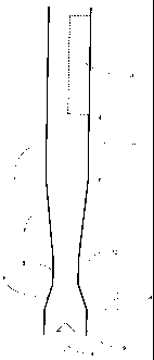
The present invention relates to a method and apparatus for measuring the flow
rates and volume fraction
of a multiphase mixture in a pipe. The invention contains tree elements. A
vertical tubular section 1, a
flow conditioning device 2, which also may be a combined conditioning device
and measurement device,
and a measurement device 3. The purpose of the flow conditioner is to
condition the multiphase fluid such
that the gas and liquid(s) are distributed symmetrically along the radius of
the pipe. Moreover, the purpose
of the flow conditioner is to create a flow regime, which for the purpose of
this patent application, is
defmed as a swirl free symmetrical annular gas concentration which for
simplicity here after referred to as
symmetrical annular gas concentration or just SAGC. Element 3, located
downstream the flow condition
device 2, is a device suitable for measuring the gas and liquid(s) component
fractions in a symmetrical
annular gas concentration flow regime.
Symmetrical annular gas concentration means that there is a higher percentage
of gas (GVF) in the center
of the pipe compared to the GVF at the pipe wall, and furthermore the GVF is
constant along the
circumference of any circle with its origin in the center of the pipe and a
radius in between the center of
the pipe and the pipe wall. The rate of change in the GVF from the center of
the pipe towards the pipe all
may be linear or non-linear. For non-linear decrease of the GVF, the change
may be S-shaped, such as a
tanh function, or a step function implying that the liquid is almost
completely separated from the gas. The
latter case is normally referred to as (pure) annular flow commonly occurring
at high gas fractions such as
wetgas flow. The function describing the change in the GVF from the center of
the pipe towards the pipe
wall is, for the purpose of this patent application, referred to as the
concentration profile function.
The flow conditioner utilizes the swirl of the multiphase flow to generate a
symmetrical annular gas
concentration flow. Swirl means that the multiphase flow has an axial rotation
component as it travels
down the pipe. By directing the multiphase flow into a more narrow passage in
the pipe, the rotation speed
of the swirl increases and a SAGC flow regime is generated. By gradually
decreasing the axial rotation
speed by a gradual increase of the pipe diameter, the rotation speed of the
swirl can be reduced while
maintaining a SAGC flow regime. A venturi can be used as the flow conditioning
device 2 which also can
be a combined flow conditioning and measurement device.
Swirl is a normal occurrence for a multiphase flow in pipelines containing
bends and straight sections. The
bends redirects the flow direction introducing a rotational force to the flow.
However, if the flow line is
CA 02650713 2008-10-28
WO 2007/129897 PCT/N02006/000486
9
straight for a long section, the swirl will diminish. Under such conditions, a
pipe structure containing one
or two bends can be used upstream the flow conditioner in order to generate
the required swirl in the
multiphase flow. Alternatively, fins inside the pipe can be used to generate
swirl in the flow.
For a SAGC flow regime, simplified process tomographic measurement techniques
are ideally suited for
performing accurate measurements of the composition and flow rate of the
multiphase fluid. The basic
concept of process tomography is to use a number of sensors around the
circumference of the pipe. The
signals from the sensors are then processed to provide an image of the
multiphase flow in the cross-section
of the pipe. Since the liquid/gas distribution is symmetrical in the cross-
section of the pipe, simple
tomographic parameterization models and calculation routines for determining
the liquid/gas distribution
in the cross-section of the pipe can be used. In addition, the symmetry allows
for use of a simpler sensor
arrangement compared to conventional tomographic sensors since it is
sufficient to perform measurement
just one half-section of the pipe cross-section. The present invention also
provides for simpler calibration
of the models and sensors. For pure annular flow where all the liquid is
distributed as a film along the
wall, the composition measurement of the multiphase flow simplifies to become
a measurement of the
thickness of the liquid film along the wall. Pure annular flow is a common
occurrence at high GVPs, and
consequently the present invention allows for very accurate measurement of the
liquid fraction under such
conditions.
Below is a summary of the invention.
A flow conditioning device 2 is located downstream a device for performing
tomographic measurements 3
in a vertical tubular section 1 as shown in figure 1. The direction of the
flow is shown with an arrow 4.
Tomographic measurements means that the distribution of the fractions of the
multiphase mixture in the
cross section of the pipe is measured with sensor(s) located around the
circumference of the pipe, as
shown in figure 1, or in just one half section of the vertical tubular section
as shown by the stipulated area
3 of figure 2. The purpose of the flow conditioning device 2 is to generate a
swirl free symmetrical
annular gas concentration flow regime such that it is sufficient to measure
the individual fractions and
distribution of the individual fractions of the multiphase mixture in just one
half section of the pipe 3 in
order to calculate the individual fractions and the distribution of the
fractions of the multiphase mixture
for the entire tubular section 1. The tomographic sensor arrangement 3, as
shown in figure 2, is also
referred to as simplified tomographic measurement since symmetry in the flow
allows for measurement in
just one half cross section of the pipe to determine the distribution within
the whole pipe cross section.
Tests in the MPM MultiPhase Flow Labatory have revealed that a venturi, as
shown in figure 3, can be
used as a combined flow conditioning device 2 and measurement device. A
venturi consists of a
convergent section 5 into a narrow passage 6 in a pipe 1. By measuring the
upstream pressure 9 and the
pressure in the narrow passage 10 by means of a pressure transmitter 8, the
flow rate of the fluid(s) can be
CA 02650713 2008-10-28
WO 2007/129897 PCT/N02006/000486
determined. The rotation speed of any swirl in the multiphase mixture at the
inlet of the venturi, will be
accelerated in the convergent section 5 generating a symmetrical annular gas
concentration flow regime in
the narrow passage 6 with a high rotation speed (swirl). The rotation speed of
the swirl is then retarded in
the divergent section 7 as the diameter expands back to its original size. In
the stabilization section 11, the
rotation speed of the swirl will further reduce and stabilize while
maintaining a symmetrical annular gas
concentration flow regime. Typical length of the stabilization zone is 2-3
pipe diameters. Then, a
symmetrical annular gas concentration regime will be maintained for the entire
tomographic measurement
section 3 without any swirl or with a very low rotation speed such that the
multiphase fluid for any
practical purposes can be considered as swirl free.
For long straight upstream pipe sections in front of the multiphase meter, the
multiphase fluid may be
swirl free at the inlet of the flow conditioner such that the conditioning
effect does not take place. For such
installations, bend(s) may be used upstream the flow conditioner to introduce
swirl into the multiphase
mixture as shown in figure 3. The inlet of the venturi 6 is now installed a
relatively short distance 13
downstream a bend 12. The flow direction is indicated with an arrow 4. The
direction of travel of the
multiphase flow is changed in the bend generating swirl in the flow. The swirl
can be further developed by
using multiple bends upstream the venturi 6 / flow conditioner 3.
Simplified tomographic measurements can be performed based on broad band RF
(Radio Frequency)
measurements of the dielectric constant / permittivity of the multiphase
mixture as shown in figure 4. The
device contains three transmitting antennas 14, 15, 16 and six receiving
antennas 17, 18, 19, 20, 21 and 22
for transmission and reception of electromagnetic energy. The antennas are
located in one half section of
the pipe where the angles between the antennas around the circumference of the
pipe wall are preferable
90 degrees as shown in figure 5. The antennas are coaxial conductors separated
by an insulating material
from the pipe wall penetrating slightly into the pipe acting as a dipole
antenna inside the pipe. The device
can also be used for performing velocity measurement of the multiphase fluid
by cross-correlating the
measurements performed in the different cross-sections of the pipe.
The device shown in figure 4 can be further extended by adding a photon source
and detector as shown in
figure 6. The simplified tomographic device now also contain a nuclear
detector 24 for measuring
photons 23 radiated from a radioactive source 22. The radioactive beam 23 is
preferable radiating through
the center of the pipe. Mass absorption of photons relates to the density of
the multiphase fluid and can be
used in combination with dielectric measurements of the multiphase mixture to
obtain a more accurate
measurement of the component fractions of the multiphase mixture or to extend
the component range of
the multiphase mixture.
CA 02650713 2008-10-28
WO 2007/129897 PCT/N02006/000486
11
Multiple photon absorption measurements can also be used for performing
simplified tomographic
measurements as shown in figure 7. A radioactive source 22 radiates photons
through cross section of the
pipe 1. A beam of photons 27 radiates preferable through the center of the
pipe to a detector 25. A second
beam 28 radiates through one half cross section of the pipe 1 to a second
detector 26.
Impedance measurements of the multiphase mixture can also be used for
performing simplified
tomographic measurements as shown in figure 8. Impedance means one or several
of the following
characteristics of the flow: capacitance, conductance, resistance, admittance
or inductance. A minimum of
three electrodes, 29, 30 31, are located at one half section of the pipe 1.
The angle between the electrodes
should preferable be 90 degrees. Additional electrodes (32 and 33) may also be
used to further improve
the measurement resolution. The electrodes may be in contact with the
multiphase fluid or protected from
the fluid by a dielectric material. The device in figure 8 may also be further
extended to improve the
measurement accuracy and component range by adding a photon source and
detector along the centerline
of the pipe as shown in figure 6, but for simplicity this is not shown in a
separate figure.
A dielectric probe located along the pipe wall as shown in figure 9 can also
be used to perform simplified
tomographic measurements. This device is particularly suited for performing
dielectric measurement of a
liquid film along the wall at wetgas flow conditions. The device contains a
transmitting antenna 34 and
two receiving antennas 35, 36 separate different distances 38, 39 from the
transmitting antenna 34. The
antennas are coaxial conductors isolated by an insulating material from the
pipe wall, and penetrating
slightly into the pipe acting as a dipole antenna inside the pipe. The
antennas may be made as one compact
probe iinit 41 as shown in figure 11 where the transmitting antenna 34 and the
two receiving antennas 35,
36 are electrical insulated from the metal housing 41 by ceramic glass 40. The
device in figure 9 may also
be further extended to improve the measurement accuracy and component range by
adding a photon
source and detector along the centerline of the pipe as shown in figure 6, but
for simplicity this is not
shown in a separate figure.
Figure 10 shows an extension of the device in figure 9 where a second probe
unit 38 is located a known
distance 39 from a first probe unit 39. By performing simultaneous
measurements with both probes and
cross-correlating these measurements, the velocity of the multiphase fluid can
be deducted. The device in
figure 10 may also be further extended to improve the measurement accuracy and
component range by
adding a photon source and detector along the centerline of the pipe as shown
in figure 6, but for
simplicity this is not shown in a separate figure.
CA 02650713 2008-10-28
WO 2007/129897 PCT/N02006/000486
12
Transmission and reflection methods may also be used to perform simplified
tomographic measurements
as shown in figure 12. A combined transmitting and receiving device 42 is
located at the pipe wall. The
device may either be a clamp-on device transmitting the signals through the
pipe wall 1, or transmitting
directly into the flow through a whole in the pipe wall 1. The device is
transmitting a signal, such as a
pulse with a given duration and shape. A reflected signal is received from the
multiphase mixture and
based on an analysis of the reflected signal, the individual fractions and
distribution of the multiphase
mixture is determined. The signal may be based on transmission and reception
of electromagnetic energy,
acoustic energy or photons. The device in figure 12 may also be further
extended to improve the
measurement accuracy and component range by adding a photon source and
detector along the centerline
of the pipe as shown in figure 6, but for simplicity this is not shown in a
separate figure.
Simplified tomographic measurements can also be performed based on
transmission line methods as
shown in figure 13. A coaxial conductor with an inner conductor 43, screen 45
and dielectric insulator 44
is mounted open ended flush with the pipe wall 1 as shown. This device is
particularly suited for
performing dielectric measurement of liquid(s) film along the wall at wet gas
flow conditions. By
transmitting a signal on the coaxial conductor and analyzing the reflected
signal on the coaxial line due to
the impedance difference between the coaxial cable and the pipe 1 containing
the multiphase fluid, the
fractions of the multiphase mixture can be determined. The device in figure 12
may also be further
extended to improve the measurement accuracy and component range by adding a
photon source and
detector along the centerline of the pipe as shown in figure 6, but for
simplicity this is not shown in a
separate figure.
The main steps involved in determining the component fractions and flow rates
based on the device shown
in figure 2, are as follows.
1) Perform measurement of differential loss and phase shift (transit time) of
a transmitted
electromagnetic wave from a sending antenna and received at two receiving
antennas located
different distances from the sending antenna.
2) The measurement of step 1 is performed at a broad frequency range
generating two one
dimensional arrays of differential loss and phase measurements vs. frequency.
A minimum of two
frequencies should be used, however in practice 25-100 measurement frequencies
can be used for
optimum measurement performance.
3) The measurement of step 2 is repeated for several measurement directions. A
minimum of two
measurement directions should be used, however in practice 8-15 measurement
directions should
be used for providing optimum measurement performance.
4) Calculate the complex dielectric constant and water fraction of the
multiphase mixture for all
measurement frequencies based on the differential phase measurements.
CA 02650713 2012-09-10
13
5) Calculate the complex dielectric constant and water fraction for the
multiphase mixture for all
measurement frequencies based on the differential loss measurements.
6) Calculate the measured density based on measured photon absorption
(optional for improved
component fraction range and measurement uncertainty).
7) Calculate the GVF (gas fraction) at the center of the pipe and at the pipe
wall and the water liquid
ratio (WLR) based on the measurements performed in steps 1-5 or 1-6.
8) Select a concentration profile function for the gas/liquid distribution
(GVF distribution) from the
center of the pipe towards the pipe wall based on measurements 1-5 or 1-6.
9) Calculate the cross sectional homogenized GVF, density of the multiphase
fluid based on the
result from step 7 and the selected concentration profile function from step
8. Homogenized in
this context means the corresponding value of GVF when the multiphase mixture
is evenly
distributed in the entire cross-section of the pipe.
10) Determine the flow rate oil, water and gas by combining the result of step
9 and the measurement
from the venturi 8.
11) As an alternative to step 10, determine the flow rate of oil, water and
gas based on cross
correlating measurements performed in different cross section of the pipe with
the transmitting
and receiving antennas shown in figure 4.
Below are a more detailed description of the invention and reference is also
made to the following text
books in the further discussion of the present invention:
The fundamentals of electromagnetic waves traveling in any media and the
behavior of electromagnetic
filed in a pipe (waveguide) is well described in the literature such as Fields
and Waves in
Communication Electronics" by S. Ramo, J.R. Whinnery and T. V. Duzer, (Wiley),
1993.
Fundamental principles for performing electromagnetic measurements,
electromagnetic mixing laws and
tomographic measurement techniques based on electromagnetic measurements can
be found in
"Electromagnetic mixing formulas and applications", by An Sihvola, (1EE
Electromagnetic Wave Series
47), 1999 and "Microwave Electronics - measurements and material
characterization" by
Chen et al, (Wiley), 2004 and "Aqueous Dielectrics" by J.B. Hasted (Chapman
and Hall), 1973.
Tomographic measurement techniques based on impedance measurements are well
described in
Tomographic Techniques for Process Design and Operation by M.S. Beck et al,
(Computational
Mechanics Publications), 1993 and "Imaging Industrial Flows: Applications of
Electrical Process
Tomography", Plaskowski et. al, (Bristol), 1995.
CA 02650713 2012-09-10
14
Multiphase flow measurement with photon gauge, such as a gamma densitometer,
is well described in
"Radioisotope Gauges for Industrial Process Measurements", Jackson et. Al,
(Wiley), 2004.
Methods for measuring velocity of a multiphase fluid is well described in
"Cross Correlation Flowmeters,
Their Design and Application", M.S. Beck (Adam Hilger), 1987.
Physical properties for fluids such as oil, water and gas, can be found in:
"Handbook of Chemistry and
Physics" (CRC Press) , 1993, "Complex permittivity of crude oils and solutions
of heavy oilfractions", by
Friise et al, in Journal of Dispersion Sci. Tchnology, 19(1), (1998) page 93-
126, "A formulation for the
Static Permittivity of Water and Steam at temperatures from 238 K to 873 K at
Pressures up to 1200 Moa,
Including Derivates and Debye-Hiinckel Coefficients" by D. P. Fernandez et al
J. Plays. Chem. Ref. Data,
Vol. 26, No 4, 1997 "Release on the IAPWS Industrial Formulation 1997 for the
Thermodynamic
Properties of Water and Steam", The International Association for the
Properties of Water and Steam,
Erlangen, Germany.
The method is based on the following fundamental principles:
1) A multiphase mixture containing water is a polar substance. Consequently,
the dielectric constant
of the multiphose fluid is frequency dependent (complex) and the dependence
vs. frequency is
well known. Hence, each measurement frequency provides a new and independent
measurement
of the complex dielectric constant of the multiphase mixture.
2) Discontinuities in a multiphase fluid cause's scatter of the transmitted
wave which has the effect
of attenuating the wave in the direction of travel. Scatter has a large effect
on the loss and is
dependent on the measurement frequency and on the size and number of
scattering objects such as
gas bubbles. Hence, each new measurement frequency provides a new and
independent
measurement of the size and number of the scattering objects in the direction
of travel for the
electromagnetic wave. The transit time (phase measurement) is far less
affected by scatter in a
multiphase stream compared to the loss measurement (ref Microwave
Determination of Moisture
in Coal: Comparison of Attenuation and Phase, Journal ofMicrowave Power, 16,
3&4 ¨1981).
Hence by performing both loss and phase measurements at the same measurement
frequency, two
independent measurements of the scatter is performed in the same direction of
travel for the
electromagnetic wave.
3) By performing the measurements described in pt 1 and 2 above in many
directions within the
pipe, parameters describing the location and concentration of the gas bubbles
can be derived such
as GVF at the pipe wall, GVF at the center of the wall and determination of an
appropriate
CA 02650713 2008-10-28
WO 2007/129897 PCT/N02006/000486
concentration profile function describing the transition of the GVF from the
center of the pipe
towards the pipe wall.
The general equation for the electric field of a positively traveling
electromagnetic wave in free-space
with x and y components of the electric field traveling in the direction z can
be described by the following
equation:
Equation 1:
E = E1 + j.)E2ei'')e-frz
where:
Electric field vector
Electric field in x direction
E2 = Electric field in y direction
V= Phase angle between x and y component
Phase constant or wave number
For an electromagnetic wave traveling in a lossy medium such as a mixture of
oil and/or gas dispersed in
water, the wave number k becomes a complex number as shown in equation 2
below.
Equation 2:
k = a + j,6
where:
a = Wave attenuation coefficient
Wave phase constant
The exponential propagation factor for phasor waves, Cik ,of equation I then
becomes,
Equation 3:
e-ikz = ee-jflz
Where a and [3 can be calculated according to equation 4 and 5 below:
Equation 4:
CA 02650713 2008-10-28
WO 2007/129897 PCT/N02006/000486
16
6"
a = (¨)[11 1+ (-7)2 -1
A 2 6
Equation 5:
= co (¨Pg ) 111 + (¨re" )2 +1
2 e
where:
s'= Real part of the complex dielectric constant for the
media
aft Imaginary part of the complex dielectric constant for
the media
co= Frequency
11 == Permeability of the media
, where complex dielectric constant c of the media can be described according
to equation 6 below:
Equation 6:
e =
For air, gas, oil and condensate, the imaginary part of the dielectric
constant is for all practical purposes
zero. For water, the complex dielectric constant can be described by a single
Debye relaxation law as
shown below:
Equation 7:
6s ¨ 6o3 = water
eivater s co
1+ a)60
where:
Ewater = Complex dielectric constant of water
Dielectric constant at infinite frequencies
cs= Static dielectric constant
Frequency
water = Conductivity of water
CO Boltzmann's constant
CA 02650713 2008-10-28
WO 2007/129897 PCT/N02006/000486
17
Equation 7 can be re-arranged for calculation of the real (s') and imaginary
(s") part of the dielectric
constant of water as shown in equation 8 and 9 below:
Equation 8:
e = ______________________________________
1+ (on)2
Equation 9:
e ___________________________________
ss
(tor) + ________________________________________
1+ (con2 co8o
where:
es Static dielectric constant
Dielectric constant at infinite frequency
Gwater Conductivity of water
Dipole relaxation time
Frequency
80 Boltzmann's constant
Measurements and equations of the static dielectric constant of water, the
dipole relaxation time and
dielectric constant at infinite frequencies are well described in the
literature. Some examples can be found
in J.B. Hasted which has performed a critical review of available data in
Aqueous Dielectrics (1973).
More recent data has been published by Udo Kaatze in J. Chem. Eng. Data, 1989
p371-374 and Meissner
and Wentz in Report from Boeing/AER inverstigation for CMS and "A formulation
for the Static
Permittivity of Water and Steam at temperatures from 238 K to 873 K at
Pressures up to 1200 Moa,
Including Derivates and Debye-Hunckel Coefficients" by D. P. Fernandez et al
J. Phys. Chem. Ref. Data,
Vol. 26, No 4, 1997.
There is also evidence that the static dielectric constant of water, the
dipole relaxation time and the
dielectric constant at infinite frequencies also are dependent of the salinity
of the water. The static
dielectric constant of water, the dipole relaxation time and the dielectric
constant at infinite frequencies for
fresh water can then be multiplied by a water salinity dependent correction
factor in order to obtain the
values of es, 6. and r for saline water. Some examples of the equations for
the water salinity correction
factor for 6s, E. and 'r has been published by Meissner and Wentz in Report
from Boeing/AER
inverstigation for CMIS page 17, J.B. Hasted, "Aqueous Dielectrics" (Chapman
Hall 1973).
CA 02650713 2008-10-28
WO 2007/129897 PCT/N02006/000486
18
The effective real part of the complex dielectric constant is:
Equation 10:
= * fl + A 1 + (;)2
eff 2
Where:
=
s' Real part of dielectric
constant
=
Imaginary part of dielectric constant
In mixture models the dielectric constant (or permittivity) of a multiphase
mixture is expressed in terms of
the effective real part of the dielectric constant of every constituting
component and their volume fraction.
Several comprehensive reviews of dielectric mixture models have been published
in the literature such as
van Beek, 1967; Tinga at al., 1973; Wang & Schmugge, 1980; Shutko & Reutov,
1982; Hallikainen et al.,
1985; Sihlova, 1989 and "Flow permittivity models and their applications in
multiphase meters", by E.
Hammer, Proc. Multiphase Metering, IBC Technical Services, Mar. 12-13, 1997,
Aberdeen. The Hanai-
Bruggeman equation, originally derived by Bmggeman (1935) and later modified
to yield complex
dielectric constants by Hanai (1936), relates the dielectric constant of a two
component mixture to the
volume fractions of the components. If the two component mixture is droplets
as an inner phase dispersed
in a continuous media of an outer phase, the equation become:
Equation 11:
( \
ginner ¨ mix outer3 Oinner
=1
6 inner 8 outer 6 mix j Oinner )outer
where:
8inner = Dielectric constant of the inner phase (dispersed phase)
Couter = Dielectric constant of the outer phase (continuous phase)
smix = Measured dielectric constant of the mixture
4:)inner = Volume fraction of inner phase (dispersed phase)
(Douter = Volume fraction of outer phase (continuous phase)
Hence, by measuring the complex dielectric constant of a multiphase mixture
and knowing the complex
dielectric constant of the individual components of the mixture such as water
and hydrocarbon, the,
volume fraction of water and hydrocarbon can be calculated.
CA 02650713 2008-10-28
WO 2007/129897 PCT/N02006/000486
19
The complex dielectric constant is determined by measuring the wave phase
constant p and attenuation
constant et of a plane electromagnetic wave propagating inside pipe. The
measurement of p is based on a
measurement of the phase difference between the two receiving antennas 17, 22
inside the pipe located at
different distances from a third transmitting antenna 15 of the sensor
arrangement shown in figure 4. The
phase measurement is performed at at least two frequencies in the range
between 1 Mhz and 10 Ghz. The
measurement can be performed with any combination of transmitters (14, 15, 16)
and receiver pairs (17,
18, 19, 20, 21, 22), but for practical purposes it is recommended to limit the
number of combinations to
27. A combination of 27 possible measurement directions is obtained by
connecting three of the
receiving antennas to a multiplexed receiver channel of an electronics device
and the remaining three
receiving antennas to a second multiplexed receiver channel of an electronics
device. This structure
prevents signal leakage between channels since the antennas are always
connected to the same input
channel of the receiver electronics. The attenuation coefficient a is measured
in a similar manner as for p
based on measurement of differential loss instead of phase.
The frequency range could also be selected based on an optimization rule for
utilizing the full dynamic
measurement range of the electronics. The frequencies are typical selected in
the range 20-4000 Mhz,
however frequencies in the range 1 Mhz to 10 Ghz may be used. The ratio
between the lowest and highest
frequency will be dependent of the choice of measurement frequencies and
capabilities of the
measurement electronics. Provided that there is sufficient loss, the
propagating electromagnetic wave
between the sending antenna and receiving antennas will behave according to
plane wave theory.
According to plane wave theory, the phase difference between the receiving
antennas can be described as:
Equation 12:
A cc, = * Z
where: Acp = Phase difference between receiving antennas
13 = Propagating wave phase constant (ref. equation 5)
Z= d2-d1
d1= Distance from transmitting antenna to the first receiving antenna
d2= Distance from transmitting antenna to the second receiving antenna
Hence, by measuring the phase difference Acp and knowing the value of Z for
the system, the phase
constant 0 for the wave propagating from the sending to the receiving antennas
can be determined.
Experiments has shown that the value of Z is also a function of the wavelength
of the transmitted signal
CA 02650713 2008-10-28
WO 2007/129897 PCT/N02006/000486
and there is also a slight dependence on Z on the conductivity of the
multiphase fluid. This is due to the
fact that the receiving antennas are located in the near field of the
transmitting antenna and the model for
plane wave propagation is then not completely valid. One way to model this is
to use a phase and
conductivity dependent calibration factor Z. This is due to the fact that the
effective antenna distance Z is
a function of the transmitted wavelength which again is a function of the
measured phase difference
between the two receiving antennas. The effective distance Z has also found to
be dependent on the
multiphase conductivity, which probably is related to the spread of the field
in the senor. Z can then be
calculated as shown in equation 13 below:
Equation 13:
Z = f(A0,0)
Where:
=
Effective antenna distance (calibration constant)
Asp : Measured phase difference
amix : Conductivity of the multiphase mixture
The conductivity of the oil/water mixture can be calculated according to the
Maxwell Garnett mixing
formula as shown below:
Equation 14:
¨ water
Cr mix Cr water + 3 * * * CS
water
Croil ¨ 2 * awater 0011*( -oil Crwater)
Where:
amix Conductivity of the oil water mixture
aoil Conductivity of the oil
cTwater Conductivity of the water
: Fraction of oil in the liquid phase
The complex dielectric constant can be determined in an iterative calculation
loop. Assuming a constant
ratio between the real and imaginary part of the dielectric constant when
performing these iterations
simplifies the calculations considerable. Experiments have shown that by using
the same ratio between the
real and imaginary dielectric constant as for pure water for a mixture of
water and oil, accurate
calculations of the volume fractions can be obtained. This approximation
introduces only small
measurement errors since the Bruggeman mixing formula is a fairly linear
function.
CA 02650713 2008-10-28
WO 2007/129897 PCT/N02006/000486
21
Hence, the ratio between the real and imaginary dielectric constant is defined
as:
Equation 15:
K _ water
et water
The real part of the dielectric constant for the mixture can thenbe calculated
by combining equation 15
and 5 as shown below:
Equation 16:
2*/32
61=
CO2 *(111 +K2 +1)*//
The steps involved in order to determine the complex dielectric constant and
water fraction of the
multiphase mixture based on the differential phase measurement is shown below:
1) Measure phase difference zip at a pre-determined frequency co
2) Calculate real and imaginary dielectric constant of water according to
equations 8 and 9
3) Calculate K according to equation 15
4) Calculate conductivity of the oil/water mixture based on the last
calculation of the oil fraction and
the conductivity of water and oil using equation 14
5) Calculate effective antenna distance Z using equation 13
6) Calculate measured value of p using equation 12
7) Calculate the real part of the dielectric constant for the oil/water
mixture using equation 16
8) Calculate the imaginary part and effective real part of the dielectric
constant of the oil/water
mixture using equation 15 (imaginary part) and 10 (effective real part)
9) Calculate the volume fraction of water based on the effective real part
of the dielectric constant of
water oil and the oil/water mixture using equation 11.
10) Repeat steps 4-9 until the calculation of the water fraction has converged
11) Repeat steps 2-10 for next measurement frequency
12) Repeat steps 1-11 for next measurement direction
The measured loss is treated in much the same way as the phase measurement by
replacing step 6 with a
calculation of a instead of p.
CA 02650713 2008-10-28
WO 2007/129897 PCT/N02006/000486
22
The attenuation coefficient a of the multiphase mixture at any measurement
frequency can be calculated
based on the following equation:
Equation 17:
AP ¨P
a = offset *in(l 0)
20* Z
where:
a = Attenuation coefficient of the multiphase mixture at a given
fi-equncy
dP = Measured differential loss [dB]
Po =ffot Power offset calculated in equation 15 [dB]
=
Effective antenna distance calculated according to equation 13
The term Poffset is needed to correct the measurement for the effect of the
antenna area exposed in a
particular direction of the pipe. The area of the antenna determines the
coupling efficiency of the antennas,
and hence the received differential loss is also affected by different antenna
area exposed in the various
direction of travel. However this can easily be modeled as a phase
(wavelength) and multiphase
conductivity dependent offset value in dB terms (decibel) as shown in equation
18 below:
Equation 18:
Poffset = f (A Crmix
Where:
Acp : Measured phase difference
amix Conductivity of the multiphase mixture
The steps involved in order to determine the complex dielectric constant and
water fraction of the
multiphase mixture based on the differential loss measurement is similar to
the steps involved for the
phase measurement by replacing step 6 by a calculation of Poffset and a
instead of 13.
CA 02650713 2008-10-28
WO 2007/129897 PCT/N02006/000486
23
It is well known that loss due to scatter is highly frequency dependent.
Scattering means that a disturbance
such as a gas or liquid bubble re-radiates parts of the electromagnetic energy
such that the energy is lost in
the direction of travel towards the receiver. Scattering is normally divided
into Rayleigh scattering and
Mie scattering which are further described in "Electromagnetic Mixing Formulas
and Applications" by
Ari Sihvola LEE Electromagnetic Waves series 47.
The Rayleigh scattering of a dielectric sphere such as a liquid droplet is
given, according to Sihvola, by
the following equation:
Equation 19:
_3 2(2,1-Vii06.0 )4 8inner ¨
outer
8 8inner + 26. outer
Where
as : Scattering cross section
a diameter of the scattering object
=
frequency
110 =
Permeability of free space
80 =
Dielectric constant of free space
Sinner Dielectric constant of the scatter object
sower Dielectric constant of the continuous phase
As seen from equation 19, the effective scattering section of an object
greatly increases with frequency.
Based on the measured differential loss and phase at all measurement
frequencies, a model for
determining the GVF at the wall and at the center of the pipe can be derived
and a selection rule for the
appropriate liquid/gas concentration profile function. The most convenient way
to derive the model is
through empirical experiments in a multiphase flow laboratory where the flow
rates of oil, water and gas
can be individual controlled in addition to the distribution of the liquid and
gas in the cross section of the
pipe. The MPM MultiPhase Flow Laboratory particularly designed for this
purpose. Based on recorded
measurements of phase and loss at all measurement directions and frequencies
and known values for the
GVF in the center of the pipe, GVF at the pipe wall, the liquid/gas
concentration profile function and
water liquid ratio, the model can be derived empirically.
The GVF in the center of the pipe can also be determined based on measured
photon absorption using a
gamma densitometer as shown in figure 6. Adding a gamma densitometer improves
measurement
accuracy and component fraction range for the device.
CA 02650713 2008-10-28
WO 2007/129897 PCT/N02006/000486
24
Measurement of gamma ray absorption is a widely used technique for density
measurement. This
technique takes into account that absorption of photon beam radiation in any
material in the pipe (flow
meter) can be expressed by the formula:
Equation 20:
N = N oe-i`Pd
where:
Empty pipe count rate (radiation)
Measured count rate (radiation)
Radiation mass absorption coefficient of the material inside the pipe.
Transmission length of the radiation through the cross-section of the pipe
Density of the material inside the pipe
Details for how to calibrate and determine GVF and density of a multiphase
mixture based on nuclear
detectors are described in more detail in "Radioisotope Gauges for Industrial
Process Measurements",
Jackson et. Al, (Wiley).
The homogen GVF and density can then simply be calculated based on integration
methods based on the
measured GVF at the wall and at the center of the pipe and the selected
concentration profile function
describing which together with the value of the GVF at the center and at the
wall determines the value of
the GVF at any point along the radius of the pipe.
Knowing the liquid and gas velocities, the oil, water and gas flow rates can
be calculated based on the
homogen GVF and water liquid ratio (WLR).
The dielectric constant of the mixture may also be determined based on
reflection techniques and
techniques based on measurement of the cut-off frequency of the pipe. In the
first case, the venturi can be
used as a reflecting device for an incoming electromagnetic wave. By
determining the frequency for when
the reflecting wave is out of phase with the transmitting wave at receivers
located in the longitudinal
direction of the pipe, the dielectric constant of the material within the pipe
can be determined. The
reflection frequency can be determined based on both phase and loss
measurements.
CA 02650713 2008-10-28
WO 2007/129897 PCT/N02006/000486
The measured dielectric constant based on the measured reflection frequency
follows the well known
formula:
Equation 21:
k22
Where = Measured dielectric constant
k2 = Measured frequency in air
fe = Measured frequency of multiphase mixture
The cut-off frequency and reflection frequency will be fairly wide apart, such
that a broad band
measurements can be obtained. The measurements can also be performed in
multiple directions as
described for the measurements of a and 13 and combined with the a and p
measurement in order to
determine the GVF at the center, GVF at the wall and the GVF concentration
profile function.
Other methods for performing tomographic measurements based on electromagnetic
signals are described
in "Electromagnetic Techniques of Nondestructive Testing of Dielectric
Materials: Diffraction
Tomography", by Bramanti et. al., Journal of Microwave Power and
Electromagnetic Energy, vol. 27,
No.4, 1992 and "Cylindrical Geometry: A Further Step in Active Microwave
Tomography", IEEE
Transactions on Microwave Theory and Theory and Techniques, Vol. 39, No. 5,
May 1991.
One way to obtain the liquid and gas velocity is by using cross correlation
techniques. Cross correlation
techniques are frequently used for measurement of multiphase flow and are well
described in Cross
Correlation Flow Meters, their design and applications by M S Beck and A
Plaskowsld (Adam Hilger,
Bristol) - 1987.
By transmitting a carrier transmitted into the flow on a transmitting antenna
14 and measuring the
response, the received signal on antenna 17 and 18 contain information of the
variations in the flow
caused by amplitude (loss), phase or frequency modulation by the disturbances.
By performing the
measurements at two sections of the pipe, such as 14 17 18 and 16 21 22
located at a known distance 49,
one can create two time varying signals that are shifted in time equal to the
time it takes the multiphase
flow to travel between the two sections. Additional measurements can be
obtained by using the antennas
15 19 20.
CA 02650713 2008-10-28
WO 2007/129897 PCT/N02006/000486
26
By cross correlating the two signals using the formula:
Equation 22:
1 T
RY (r) = x(t * y(t)dt
x T 0
where x(t) and y(t) are the sampled signals, the time delay can be calculated.
The time delay r between
the signals x(t) and y(t) is a measure of the time it takes a disturbance in
the flow to go from the first to the
= second pair of antennas.
It is common for cross-correlation based flow meters based on electromagnetic
signals (i.e. capacitive,
inductive and RF based flow-meters) to use a carrier or measurement signal
with a frequency substantially
below the cut-off frequency in order to obtain isolation between the
measurement sections.
The cut-off frequency of the lowest mode in a circular wave guide (TEii) is
according to Ramo et al given
by equation 23 below;
Equation 23:
0.293
fe =
Where
=
Permeability within the sensor (pipe)
=
Dielectric constant within the sensor (pipe)
a = Pipe diameter
The cut-off wavelength is given by:
Equation 24:
=3.41a
Where a = Pipe diameter
According to Ramo et al, there is attenuation without phase shift for
frequencies below the cut-off
frequency of a wave guide and phase shift without attenuation for frequencies
above the cutoff frequency,
and neither attenuation nor phase shift exactly at cutoff. It is also well
known that this fimdamental
CA 02650713 2008-10-28
WO 2007/129897 PCT/N02006/000486
27
behavior of a wave guide can be used to measure the cut-off frequency of the
pipe by measuring the
location of the phase shift. Based on the measured frequency, the dielectric
constant of the multiphase
mixture within the pipe can be derived according to equation 22.
The attenuation coefficient for an electromagnetic wave traveling in the
longitudinal direction of the pipe
can according to Ramo et.al be calculated according to equation 25 below:
Equation 25:
v
Where
a = Attenuation coefficient
=
Ac Cut-off wavelength
=
=
fc Cut-off frequency
=
=
Measurement frequency
Hence, by using a measurement frequency that is substantially below the cut-
off frequency, the ratio f/fc is
much less than 1 such that the attenuation in the longitudinal direction of
the pipe becomes substantially
independent of frequency. By combining equation 24 and 25 the attenuation
coefficient then approximates
the constant value:
Equation 26:
271
a = ________________________________
3.41a
where a = pipe diameter
Hence, by measuring or calculating the cut-off frequency of the pipe and
selecting a measurement
frequency that is substantially below the cut-off frequency, energy traveling
in the longitudinal direction
of the pipe is minimized providing electromagnetic isolation between the
upstream and downstream
measurement cross sections of the pipe.
Signal processing methods for determination of liquid and gas velocities based
on cross correlation
measurements is well known as described in "Simulation of two peaks
correlation method for gas- liquid
flow velocity measurements", PhD at UMIST, 1985 bt Corral Davalos, and
"Development of signal
CA 02650713 2008-10-28
WO 2007/129897 PCT/N02006/000486
28
interpretation models for multiphase flow rate metering of oil - water - gas
flow", PhD at University of
Bergen 1996 by Oivind Midttveit, "A pulsed ultrasound cross correlation system
for velocity
measurement in two component fluids", PhD at UMIST 1986 by Xu L-A and
"Analysis of Space and
Time Structures in Two Phase Flow using Capacitance Sensors", PhD University
of Stavanger 1993 by
Rune Viggo Time.
A venturi flow meter is commonly used for measurement of flow rate of a
multiphase fluid. Any
restriction in the pipe will result in a change in the velocity of the
multiphase mixture and introduce a
pressure drop across the restriction. Based on the theory of fluid dynamics,
the square root of the pressure
drop is proportional to the total mass flow rate in the pipe. A venturi tube
is a structure where the pipe
diameter is gradually reduced into a section of the pipe with a smaller
diameter. The smaller section may
be short or a relative long section. Then the diameter is gradually expanded
to the original size of the
pipe. Mass flow measurements with such a structure are described in the ISO
standards 5167
"Measurement offluid flow by means of pressure differential devices inserted
in circular cross-section
conduits running full" part 1 ¨ general principles and part 4 ¨ venturi tubes.
According to ISO 5167-1, the mass flow rate can be calculated as:
Equation 27:
Qm= ______________________________ C ___ d 2 112pAp
111¨ ft4 4
where:
Qm = Total mass flow rate
Discharge coefficient
13= Diameter ratio between venturi throat and pipe
Diameter of venturi throat
Ap Measured pressure drop between inlet and venturi throat
Density of the multiphase mixture
The adoption of venturi tubes for multiphase and wetgas flow conditions are
further described in "Design
of a flow metering process for two-phase dispersed flows", Int. J. Multiphase
Flow vol 22, No 4, pp 713-
732, "A study of the performance of Venturi meters in multiphase flow", by
Hall, Reader-Harris, and
Millington, 2I'd North American Conference on Multiphase Technology and
"Liquid Correction of Venturi
Meter Readings in Wet Gas Flow", by Rick de Leeuw, North Sea Flow Measurement
Workshop ¨ 1997.
CA 02650713 2008-10-28
WO 2007/129897 PCT/N02006/000486
29
The device shown in figure 9 can also be used to perform simplified
tomographic measurements of the
flow. The device is particularly suited when the concentration distribution
function approximates a step
function such that most of the liquid is distributed along the wall. This is a
common occurrence at wetgas
flow conditions. The complex dielectric constant is determined in much the
same way as described above
by performing a measurement of the attenuation coefficient a and phase
coefficient 13 at a broad frequency
range by transmitting on antenna 34 and receiving on antenna 35 and 36.
However, in this case the
concentration distribution function is assumed to be a step function and the
GVF at the wall is zero, such
that the measurement simplifies to become a measurement of the thickness and
composition of the liquid
film.
Two of the devices shown in figure 9 can also be combined as shown in figure
10 seperated by a known
distance 39. By using cross-correlation techniques as described above, the
liquid and gas velocities can be
derived.
By using two gamma detectors from a single radioactive source as shown in
figure 7, the fractions and
liquid distribution of a two phase flow can be determined. Further details of
how to perform the
calculations can be found in "Radioisotope Gauges for Industrial Process
Measurements" by Jackson et.
al. and "Cross-Section Averaged Density and Mass Flux Measurements in Two-
Phase Flow Through
Pipes" by Heithick et. al., ASME Measurements in Polyphase Flows, 1-9 (1978).
Sensors for performing tomographic measurements based on impedance
measurements have been known
for several decades. Impedance sensors can either be based on measurement of
capacitance (ECT),
resistance (ERT) or inductance electromagnetic (EMT). The working principle
and design of tomographic
impedance sensor as shown in figure 8, is well described in Tomographic
Techniques for Process Design
and Operation by M.S. Beck et al, -Computational Mechanics Publications
(1993), "A Novel Approach
to Reconstruction of Process Tomography Data", by 0. Isaksen, PhD at
University of Bergen (1996) and
"Imaging Industrial Flows. Applications of Electrical Process Tomography",
Plaskowski et. al, Bristol
(1995)
Transmission and reflection methods are well known method for material
characterization as shown in
figure 12 and 13. These devices are particularly suited when the concentration
distribution function
approximates a step function such that most of the liquid is distributed along
the wall. This is a common
occurrence at wetgas flow conditions. For acoustic signals, the time it takes
an acoustic pulse to travel
forth and back from the reflection surface represented by the liqud/gas
interface, can be used to measure
liquid film thickness. Knowing the distance to the pipe wall from the acoustic
transmitter and receiver, the
thickness of the film can be determined.
CA 02650713 2008-10-28
WO 2007/129897 PCT/N02006/000486
Electromagnetic methods can be based on a radiating slot through the wall as
shown in figure 12 or by
using an open ended coaxial conductor as shown in figure 13. A pulse or
continuous frequency is
transmitted on the coaxial cable 43. Based on a measurement of the amplitude
and phase variations
reflected back on the coaxial conductor, the complex dielectric constant of
the material within the pipe can
be determined such that the thickness and fractions of the liquid film can be
derived. The design and
working principles of transmission and reflection sensors as shown in figure
12 and 13 is further described
in "Microwave Electronics ¨ measurement and material characterization" by Chen
et. al., Wiley (2004),
and "Permittivity Measurements of Thin Liquid Film Layers using open-ended
Coaxial Probes", Meas.
Sci. Technol., 7 (1996), 1164-1173.