Note: Descriptions are shown in the official language in which they were submitted.
CA 02650747 2010-12-03
21182-352
COMMINUTING DEVICE WITH COUNTER-ROTATING ROTORS
Description:
The invention relates to a device for comminuting feedstock.
The comminuting of feedstock is a central component of mechanical process
engineering in which a starting material is divided by separation into smaller
parts. In
this case, the feedstock is altered in its size, form, or composition in view
of its later use.
Separation methods suitable for this provide for comminuting by means of
tearing,
beating, rubbing, grinding, or cutting. An example is the preparation of waste
products,
in which size reduction of the feed material is a requirement for processing
in
subsequent processing stations or in which separation into various components,
present in the feedstock, occurs simultaneously during comminuting.
It is known for comminuting by means of cutting to move the cutting edges of
cutting
tools past one another to execute an effective motion. Apart from the type of
feedstock
and its insertion during the cutting process, the cutting geometry determined
by the
machine structure as well is a major determining factor for the cutting
process. To
achieve a clean cut, it is necessary in particular that the active cutting
edges of the
cutting tools slide past one another while maintaining an optimal blade
clearance, which
depends on the type of feedstock. With an increase in the distance between the
jointly
acting cutting edges, the effectiveness of the cutting process declines,
because part of
the energy to be applied for grinding, tearing, or crushing the feedstock is
used up. As a
result, increased mechanical stress arises, which accelerates signs of wear,
reduces
operating reliability, and not least increases energy consumption. Maintaining
an
optimal cutting geometry is very important therefore.
U.S. Pat. No. 4,684,071 discloses a device for comminuting used tires, in
which a
vehicle tire is divided by means of counter-rotating cutting rotors. The
cutting rotors
consist of cutting discs which are arranged on a shaft at an axial distance
and are
2
CA 02650747 2009-01-23
populated at their circumference with cutting tools, whereby the cutting discs
of the one
rotor engage with a smaller radial overcutting into the gaps of the other
cutting rotor.
Because the cutting tools are exposed to great mechanical stress during
operation and
have a correspondingly great wear, the cutting tools are affixed detachably to
the cutting
discs, so that they can be replaced by new or resharpened tools.
Two possible ways of affixing the cutting tools to the cutting discs are
disclosed in U.S.
Pat. No. 5,730,375. It is possible, on the one hand, to form the
circumferential surface of
each cutting disc in the shape of a polygon, which results in a planar support
surface for
the cutting tools. The cutting tools are bolted down by means of radially
acting bolts,
which are accessible from the top side of the cutting tools and extend into
the
circumferential area of the cutting discs, whereby the heads of the bolts come
to lie
within corresponding recesses. Because during damage to cutting tools due to
rough
comminuting operation the support surface for the cutting tools and the tapped
holes in
the cutting discs become damaged and must be repaired when the cutting tools
are
changed, another embodiment, depicted in U.S. Pat. No. 5,730,375, comprises
affixing
the cutting tools with the interconnection of a bearing plate on the outer
circumference
of the cutting discs. This has the advantage that in the case of damage only
the bearing
plates need to be replaced but the entire support surface of the cutting discs
need not
be resharpened. In addition, to take up the fixing bolts bushings are
provided, which
have both an inside and outside thread and are screwed into radial holes in
the disc
rotor. With their inside threads, the bushings in turn take up the fixing
bolts. If an inside
thread is damaged, the threaded bushing can be replaced as a whole unit
without
having to work on the disc rotor itself.
During operation of comminuting devices of this type, large axial forces
arise, which are
passed via the cutting tools to the cutting discs. These forces must be
absorbed by the
fixing bolts, which are stressed thereby by shearing and bending. Because the
load
bearing capacity of each bolt is limited, the removal of the total load
requires a relatively
large number of fixing bolts, which, when the cutting tool is changed, entail
a
correspondingly large amount of work because of their loosening and
retightening.
3
CA 02650747 2009-01-23
Another factor is that the positioning of the cutting tools on the cutting
discs is carried
out with the fixing bolts. As a result of the play between the cutting tool
and the fixing
bolt, large tolerances arise during the setting of the blade clearance, which
are an
obstacle to maintaining a precise cutting geometry and entail the previously
described
negative effects on the cutting process.
Another factor is that based on geometric circumstances and static
requirements, the
fixing bolts may be disposed only with maintenance of a minimum distance to
the
transverse edge of the cutting tools. The arising leverages with a nonuniform
load
application during the comminuting process lead to a nonoptimal load removal,
which
must be considered in dimensioning the fixing bolts.
To find a remedy here at least in part, European Pat. No. EP 1 289 663 Al
discloses a
rotor for a generic comminuting device, in which the cutting tools are affixed
laterally to
a tool holder by means of screws, optionally with the interconnection of
compensating
plates. The thus arising cutting unit comprising tool holder and cutting tools
is affixed by
radially acting screws at the outer circumference of a cutting blade, whereby
positioning
pins are provided for exact positioning of the cutting unit. As a result, the
positioning
accuracy of the tool holder relative to the cutting disc is in fact improved,
but
dimensional inaccuracies are again introduced into the system by the screwing
of the
cutting tools to the tool holder, optionally with inserted distance plates;
these in turn
undo this advantage.
In view of the static load removal behavior, in this type of construction,
axial stress is
introduced via the fixing screws and the positioning pins into the cutting
discs with a
load removal cross section limited by the number and diameters of the screws
or pins.
In addition, here as well no optimal force transfer from the cutting tool to
the cutting disc
is possible, because the positioning pins due to construction must also
maintain a
minimum distance to the transverse edges of the tool holder.
4
CA 02650747 2010-12-03
21182-352
On this background, the object of some embodiments of the invention is to
provide
a device in which the cutting process is carried out with the greatest
precision
possible with simultaneous improvement of the load introduction into the
cutting
discs and with minimizing of the effort for changing the cutting tools.
In one aspect, the present invention provides a device for comminuting
feedstock
comprising a cutting assembly with a first rotor and at least one second
rotor, each
of which rotates around its longitudinal axis with an opposite rotation
direction,
wherein each rotor is provided with a number of cutting discs and a number of
spacer discs, whereby the spacer discs have a much smaller diameter compared
with the cutting discs and are located between the cutting discs so that the
cutting
discs are arranged at an axial distance to one another, and wherein the
cutting
discs of the first rotor are located on gaps, with the result that in each
case a
spacer disc and a cutting disc lie opposite each other in radial direction,
and
wherein the cutting discs of the first rotor are located with radial
overlapping
relative to the cutting discs of the second rotor in a way that a radial
overlapping of
the cutting discs is assured in each position of the cutting discs, and
wherein the
cutting discs along their circumference have support surfaces for accepting
cutting
tools, whose longitudinal cutting edges move past one another over the course
of
the rotation of rotors with formation of a cutting clearance, wherein the
cutting disc
and the cutting tool constitute a common contact area, a positive fit groove
is
arranged in the common contact area to create a positive fit between the
cutting
tool and cutting disc, the positive fit groove is running in the plane of the
cutting
disc, and at least one positive fit strip engages with said positive fit
groove.
The principle of the invention is the separation of the functional units for
secure
and positionally accurate fixation of the cutting tools on the cutting discs.
In this
case, a splitting of functions occurs, on the one hand, in the clamping down
and
securing of the cutting tools on the cutting disc, and, on the other, in the
securing
of the snug fit of the cutting tools in the predefined desired position on the
cutting
disc.
-5-
CA 02650747 2010-12-03
21182-352
The clamping down of the cutting tool according to the invention is carried
out with
radially acting bolts. Experience has shown that bolts are not up to the rough
comminuting operation within generic devices and are therefore frequently bent
or
otherwise damaged, so that loosening of bolts and thereby replacement of the
comminuting tools are possible only with great effort, and the bolts usually
need to
be replaced by new ones.
Because in a device of the invention the fixing bolts are only stressed during
pulling and are therefore free of transverse force and momentum stresses,
their
axial load-bearing behavior can be fully utilized.
The other functional units to secure the snug fit of the cutting tool are used
primarily to secure the position of the cutting tool in the axial direction to
assure
the optimal cutting clearance and thereby the optimal cutting geometry. By
placing a positive fit groove on one side and a positive fit strip on the
other side, in
comparison with known devices,
-5a-
CA 02650747 2009-01-23
relatively large areas for absorbing the load arise, which also permit the
introduction of
large forces securely into the rotor without damage to the comminuting tools.
For the advantageous case that the positive fit groove and the positive fit
strip extend
over the entire length of the bottom side of the cutting tool, very favorable
starting
geometric conditions arise to keep a secure position also with a nonuniform
load
application.
According to an advantageous embodiment of the invention, the positive fit
groove has
a cross section that narrows trapezoidally toward the bottom of the positive
fit groove.
This facilitates, on the one hand, the setting of the cutting tool on the
cutting disc. On
the other hand, loosening of the cutting tool is promoted by this, because
jamming or
wedging of the positive fit strip in the positive fit groove is effectively
prevented.
It is preferred according to the invention that the positive fit groove and
the positive fit
strip extend over the entire length of the bottom side of the cutting tool
and/or the
support surface of the cutting disc. This does not rule out, however, that the
positive fit
groove or at least the positive fit strip may also be discontinuous. This type
of
embodiment of the invention advantageously has positive fit strips that engage
in the
positive fit groove sectionally at least in the end regions.
Another advantageous embodiment of the invention provides that the
longitudinal sides
of the cutting tools are made in such a way that with optional wear plates at
the side
surfaces of the cutting disc they effect their fixation in the desired
position. Thus, the
wear plates without further action are simultaneously attached to the cutting
discs with
the assembly of the cutting tools.
The invention will be described in greater detail hereafter with use of an
exemplary
embodiment shown in the drawings. The figures show the following:
6
CA 02650747 2009-01-23
FIG. 1 shows a vertical section through a device of the invention along the
line I-I
depicted in FIG. 2;
FIG. 2 shows a top plan view of the device depicted in FIG. 1;
FIG. 3 shows an oblique view of the cutting tool of the device depicted in
FIGS. 1 and 2;
FIG. 4 shows a longitudinal section through the rotor shown in FIG. 3;
FIGS. 5a and b show a first embodiment of the attachment of a cutting tool to
a cutting
disc in cross section and in the associated partial view;
FIGS. 6a and b show a second embodiment of the attachment of a cutting tool to
a
cutting disc in cross section and in the associated partial view;
FIGS. 7a and b show a third embodiment of the attachment of a cutting tool to
a cutting
disc in cross section and in the associated partial view; and
FIGS. 8a and b show a fourth embodiment of the attachment of a cutting tool to
a
cutting disc in cross section and in the associated partial view.
FIGS. 1 to 4 show the general structure of a device of the invention in the
form of a
double shaft shredder 1, which is suitable, for example, for the pre-
comminuting of used
tires, but also for the preparation of electronic waste and other materials.
Double shaft
shredder 1 has a rectangular housing 2, which is open upward and downward and
with
its cross walls 5 and longitudinal walls 6 encloses a working space 7. Housing
2 rests
on a supporting frame 3, whose top side is covered by cover plate 4 around
housing 2,
to form in this manner a platform for other machine components.
A funnel-like material outlet 9, through which the sufficiently comminuted
material is
discharged from double shaft shredder 1, is connected to the lower opening of
housing
2. Feed hopper 8, which is flush with cross walls 5 and longitudinal walls 6
and over
which the feedstock is loaded into double shaft shredder 1, is attached to the
upper
opening of housing 2. Internals joining longitudinal walls 6 extend within
feed hopper 8
for material charging. These consist, on the one hand, of a chute 10,
adjustable in
inclination, and, on the other, of conveying rollers 11, whose shafts 12 have
star-shaped
gripping wheels 13 and which are caused to rotate oppositely by electric
drives 14 on
the outside of the one longitudinal wall 6.
7
CA 02650747 2009-01-23
The cutting tool, which performs the comminuting of the feedstock, is located
in cutting
chamber 7. The cutting tool comprises substantially two rotors 15 and 16,
which are
disposed at a predefined distance, axis-parallel to one another, and with an
opposite
rotation direction between longitudinal walls 6. The structure of rotors 15
and 16 is a
mirror image each with a drive shaft 17, which is supported rotatable in
bearings 18
disposed on the outside of longitudinal wall 6. In each case, an end of drive
shaft 17 is
coupled to a hydraulic rotary drive 19, which causes the rotation movement of
each
rotor 15 and 16 in the rotation direction shown by arrows.
As is evident primarily from FIGS. 3 and 4, rotors 15 and 16 have a plurality
of cutting
discs 20 and spacer discs 21, which are seated alternately on drive shaft 17.
The drive
force is transferred via a positive fit between cutting discs 20 or spacer
discs 21 and
drive shafts 17 (FIG. 1). Axis-parallel bolts 22 clamp cutting discs 20 and
spacer discs
21 together.
Cutting discs 20, which have a much larger diameter compared with spacer discs
21,
have a polygonal profile at their circumference, as a result of which support
surfaces 23
with an approximate tangential course arise, which form the seat for cutting
tools 24.
The specific design of support surface 23 will be dealt with in greater detail
in the
description of FIGS. 5a to 8b.
The relative position of rotors 15 and 16 to one another is such that due to
an axial
offset by the thickness of a spacer disc 21, in each case a spacer disc 21 and
a cutting
disc 20 lie opposite each other in the radial direction. In the radial
direction, the distance
between axes of both shafts 17 of rotors 15 and 16 is selected so that a
radial
overlapping of cutting tools 23 is assured in each position of cutting discs
20; i.e.,
cutting discs 20, equipped with cutting tools 23, of both rotors 15 and 16
mesh together.
In this way, the longitudinal edges of cutting tools 24 form cutting edges 26,
which
during the cutting process are moved past one another over the course of the
opposite
8
CA 02650747 2009-01-23
rotation of rotors 15 and 16. In this regard, the structure-related axial
distance between
two jointly acting cutting edges 26 defines a blade clearance 27 (FIG. 5a),
whose size
significantly determines the quality of the cutting process. Depending on the
type of
feedstock and other parameters, there is an optimal size for blade clearance
27 in each
case, whereby deviations from this size cause the cutting process to degrade
considerably. A precise positioning of cutting edges 26 relative to one
another is very
important for this reason.
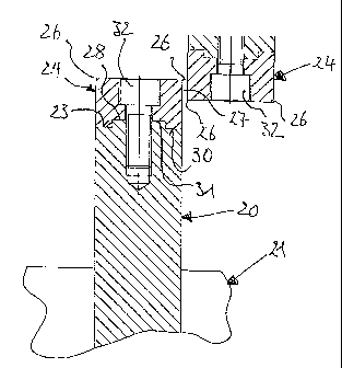
FIGS. 5a to 8b show structural solutions for the positionally precise
attachment of
cutting tools 24 to cutting discs 20. The embodiment shown in FIGS. 5a and b
is
characterized by a positive fit strip 28, which extends centrally over the
entire length of
support surface 23 at the outer circumference of cutting disc 20. Working
together with
positive fit strip 28 is a cutting tool 24, which has a complementary positive
fit groove 31
on its bottom side 30 facing support surface 23. Axial bearing surfaces on
which cutting
tool 24 braces during the action of axial forces against cutting disc 20 arise
in this way
by means of the mutually assigned side surfaces of positive fit strip 28 and
positive fit
groove 31.
FIGS. 5a and b relate to a first embodiment of the invention and thereby show
the
subarea, important for the invention, of a cutting disc 20. The support area
23 is evident
over whose entire length a positive fit strip 28 projects in the middle.
Cutting tool 24 substantially has a bar-shaped form and is fashioned of solid
metal,
preferably of hardened steel. The front end in the rotation direction is
beveled, so that
the top edge forms a grip tooth 29 for the secure drawing in of the feedstock.
The lateral
longitudinal edges at the top side of cuffing tool 24 form cutting edges 26
effective for
the cutting process.
A positive fit groove 31, which is made complementary to positive fit strip
28, runs in the
center and over the entire length on the bottom side 30 of cutting tool 24.
When cutting
9
CA 02650747 2009-01-23
tool 24 is placed on cutting disc 20, a positionally precise seating therefore
results by
itself without further action and attentiveness by operating personnel.
Two fixing bolts 32 (indicated only by axes in FIG. 5b), which extend into
cutting disc 20
radially through cutting tool 24, are used to fix cutting tool 24 in its
desired position on
cutting disc 20. The head of fixing bolts 32 is thereby countersunk in
recesses
originating on the top side of cutting tool 24.
During operation of a device of the invention, a system of load removal
thereby results,
in which axial forces are taken up via the entire sides of positive fit strip
28 or positive fit
groove 31 over their entire surface and transferred. Because there is a load
removal
surface over the entire length of cutting tool 24 thereby, greater forces
overall can be
absorbed and an optimal load removal behavior also results with nonuniform
load
applications.
In contrast, radial lifting forces are absorbed by bolts 32 alone, which
tighten cutting tool
24 against cutting disc 20. The strict separation of load removal of axial and
radial
forces successfully protects bolts 32 from a shearing force effect and the
associated
bending moment.
The attachment of cutting tools 24 to cutting discs 20 according to the
invention
therefore simultaneously enables a precise positioning of cutting edges 26,
optimal
force transfer from cutting tools 24 to cutting disc 20, and protection of
bolts 32 from
bending stress. As a result, a precise cutting geometry with high operating
reliability is
assured.
FIGS. 6a and b show an embodiment of the invention, which corresponds in large
parts
to those described for FIGS. 5a and b, so that the same reference characters
are used
for the same elements and what has been stated there corresponds accordingly.
CA 02650747 2009-01-23
There are differences only in the area of the positive fit between cutting
tool 24 and
cutting disc 20 for the precise positioning and removal of axial forces. For
this purpose,
positive fit strip 33 is arranged on the bottom side 30 of cutting tool 24 and
engages in a
positive fit groove 34 in support area 23 of cutting disc 20.
FIGS. 7a to 8b relate to embodiments of the invention, which are particularly
suitable in
relation to wear protection for the face sides of cutting discs 20. In the
case of abrasive
feedstock, circular surface 35 between spacer disc 21 and the outer
circumference of
cutting disc 20 is at risk for wear, for which reason it is already known to
protect cutting
disc 20 in the area of circular surface 35 by means of wear-resistant plates.
The
embodiments shown in FIGS. 7a to 8b combine in a special way the arrangement
of
cutting tool 24 on cutting disc 20 with simultaneous fixation of wear
protection.
An embodiment is shown for this purpose in FIGS. 7a and b in which cutting
tools 24
have a bilateral axial overhang over cutting disc 20 and have a longitudinal
base 38
projecting from the bottom side 30 and parallel to surfaces 35. Bottom side 30
in this
way forms a trough-like slot, in which cutting disc 20 comes to lie with its
outer
circumference with an accurate fit. Base 38 with its interior sides thus forms
axially
acting force transfer areas to cutting disc 20, which assure an accurately
fitting seat of
cutting tools 24 on cutting discs 20.
In addition, top sides 39 of base 38 are inclined inward, preferably at an
angle of 45 , so
that undercuts result, which with cutting disc 20 form spandrel-shaped slots
for fixation
of the wear protection.
The wear protection is formed by approximately trapezoidal plates 36, whose
lower
curved edge 40 comes to lie in hollowed-out areas 41 in the edge region of
spacer discs
21. Upper edge 42 has an inclination complementary to top side 39 of base 38,
so that
the pointed edge engages in the ring-shaped undercut of base 38 and is held in
the
axial direction. After placement and attachment of cutting tool 24, a
simultaneous
attachment of plates 36 is thereby achieved.
11
CA 02650747 2009-01-23
FIGS. 8a and b relate to an embodiment of the invention, which combines
together the
features of the examples shown in FIGS. 5a, b and 7a, b with the advantage
that base
38' is used only for fixation of plate 36 and therefore may be formed
structurally thinner.
Support area 23 of cutting disc 20 corresponds to that described in FIGS. 5a
and b with
a positive fit strip 28, which acts together with a positive fit groove 31 in
the bottom side
30 of cutting tool 24. In addition, cutting tool 24 is made broader than
cutting disc 20, as
a result of which a longitudinal base 38' is formed with the overhang.
In comparison with the embodiment in FIG. 7, the height of base 29' is
reduced,
whereby top side 39 flush with its inner edge, therefore without a step,
merges into
bottom side 30, whereas the pointed edge again forms an undercut. The
attachment of
plate 36 then occurs as already described in FIGS. 7a and b.
12