Language selection

Search

Patent 2650827 Summary

Third-party information liability

Some of the information on this Web page has been provided by external sources. The Government of Canada is not responsible for the accuracy, reliability or currency of the information supplied by external sources. Users wishing to rely upon this information should consult directly with the source of the information. Content provided by external sources is not subject to official languages, privacy and accessibility requirements.

Claims and Abstract availability

Any discrepancies in the text and image of the Claims and Abstract are due to differing posting times. Text of the Claims and Abstract are posted:

  • At the time the application is open to public inspection;
  • At the time of issue of the patent (grant).
(12) Patent: (11) CA 2650827
(54) English Title: DIAGNOSTIC TEST UNIT WITH A CONTAINER FOR TEST CARRIERS
(54) French Title: APPAREIL D'EPREUVES DIAGNOSTIQUES AVEC RECIPIENT POUR SUPPORTS DE BANDELETTES A EPREUVES
Status: Granted and Issued
Bibliographic Data
(51) International Patent Classification (IPC):
  • G01N 33/48 (2006.01)
  • G01N 33/66 (2006.01)
(72) Inventors :
  • SACHERER, KLAUS-DIETER (Germany)
  • DITSCHER, WOLFGANG (Germany)
  • STEINBRUCK, RALF (Germany)
  • RUHL, WERNER (Germany)
  • SCHOTTLE, KLAUS (Germany)
(73) Owners :
  • F. HOFFMANN-LA ROCHE AG
(71) Applicants :
  • F. HOFFMANN-LA ROCHE AG (Switzerland)
(74) Agent: NORTON ROSE FULBRIGHT CANADA LLP/S.E.N.C.R.L., S.R.L.
(74) Associate agent:
(45) Issued: 2012-03-20
(86) PCT Filing Date: 2007-05-02
(87) Open to Public Inspection: 2007-11-15
Examination requested: 2008-10-30
Availability of licence: N/A
Dedicated to the Public: N/A
(25) Language of filing: English

Patent Cooperation Treaty (PCT): Yes
(86) PCT Filing Number: PCT/EP2007/054267
(87) International Publication Number: WO 2007128758
(85) National Entry: 2008-10-30

(30) Application Priority Data:
Application No. Country/Territory Date
06009396.0 (European Patent Office (EPO)) 2006-05-06

Abstracts

English Abstract


The invention concerns a diagnostic test unit for analysing a body fluid
comprising
a test carrier (test tape 10; test strips 12) provided with test fields (38)
for applying
the body fluid and a container (14) containing the test carrier, wherein an
opening
(18) of the container (14) is at least in some areas bordered by a seal (16).
According to the invention it is proposed that the opening (18) is screened by
a
closing foil (22) from the surroundings of the container (14) and that the
test tape
(10) or a test strip (12) to be dispensed is passed through a passage gap (20)
between the closing foil (22) and the seal (16).


French Abstract

L'invention concerne une unité de test de diagnostic pour analyser un liquide corporel avec un support de test (bande de test 10 ; ruban de test 12) muni de champs de test (38) destinés à l'application du liquide corporel et un récipient (14) contenant le support de test, une ouverture (18) du récipient (14) étant bordée au moins par zone par une étanchéité (16). Selon l'invention, il est proposé que l'ouverture (18) soit protégée par une feuille de scellement (22) vis-à-vis de l'environnement du récipient (14) et que la bande de test (10) ou un ruban de test à débiter (12) soit délivré à travers une fente de passage (20) entre la feuille de scellement (22) et l'étanchéité (16).

Claims

Note: Claims are shown in the official language in which they were submitted.

-11-
Claims:
1. Diagnostic test unit for analysing a body fluid comprising a test tape
provided with test fields for applying the body fluid and a container
containing the test tape, wherein an opening of the container for dispensing
test tape is at least partially bordered by a seal, wherein the opening is
screened from the surroundings of the container by a closing foil, the closing
foil being affixed to a ring face on the container bordering the opening, at
least a portion of the ring face being formed by the seal, and where the test
tape is passed through a passage gap between the closing foil and the seal.
2. The test unit according to claim 1, wherein the test tape is inserted in
the
form of a tape roll through the opening into the container.
3. The test unit according to claim 1 or 2, wherein that the test tape has
free
carrier sections between successive test fields and that a test field-free
carrier
section is in the passage gap in a storage state.
4. The test unit according to one of the claims 1 to 3, wherein the container
is
formed by a tape cassette having a storage chamber and a waste chamber,
and wherein the test tape can be transported out of the storage chamber over
an application site into the waste chamber.
5. The test unit according to any one of the claims 1 to 4, wherein that the
rear
side of the test tape facing away from the test fields glides over the seal.
6. The test unit according to any one of the claims 1 to 5, wherein the front
side
of the test tape carrying the test fields runs towards the border of the
closing
foil.

-12-
7. Diagnostic test unit for analysing a body fluid comprising a plurality of
test
strips which each have at least one test field for applying the body fluid and
a container for receiving the test strips wherein an opening of the container
for individually dispensing test strips is at least partially bordered by a
seal,
wherein the opening is screened from the surroundings of the container by a
closing foil, the closing foil being affixed to a ring face on the container
bordering the opening, at least a portion of the ring face being formed by the
seal, and where the test strips can be passed through a passage gap between
the closing foil and the seal for dispensing.
8. The test unit according to claim 7, wherein the test strips are introduced
into
the container through the opening as a stack of strips.
9. The test unit according to claim 7 or 8, wherein that the container is
formed
by a strip magazine defining a storage chamber therein, where the test strips
can be individually pushed out of the storage chamber.
10. The test unit according to any one of the claims 7 to 9, wherein the rear
side
of a particular test strip which faces away from the test field glides over
the
seal and the front side runs against the closing foil when it is dispensed.
11. The test unit according to any one of the claims 1 to 10, wherein the
opening
forms an inlet for insert parts of the container before the closing foil is
applied.
12. The test unit according to any one of the claims 1 to 11, wherein
desiccants
in the form of functional composite injection-moulded parts are introduced
through the opening into the container.

-13-
13. The test unit according to any one of the claims 1 to 12, wherein the
closing
foil is held by a pressing element under surface pressure to minimize the
passage gap towards the seal.
14. The test unit according to claim 13, wherein the pressing element
comprises
a spring .
15. The test unit according to any one of the claims 1 to 14, wherein when the
closing foil is applied, the passage gap is kept free by a section of the test
tape or of a test strip or by an appropriately dimensioned insert.
16. The test unit according to any one of the claims 1 to 15, wherein the
closing
foil is joined along a sealing line with the container and/or the seal in a
material-tight manner.
17. The test unit according to any one of the claims 1 to 16, wherein the
closing
foil is formed by a carrier material which is provided with a heat-seal
coating.
18. The test unit according to any one of the claims 1 to 17, wherein the seal
is
designed as a single component injection-moulded part or, in combination
with the container, as a two-component injection-moulded part formed from
TPE.
19. The test unit according to any one of the claims 1 to 18, wherein the
container which is loaded with the test tape or the test strips is stored in a
tight outer packaging which is to be opened for use.

-14-
20. Diagnostic test unit for analysing a body fluid comprising a test tape
provided with test fields for applying the body fluid and a container
containing the test tape, wherein an opening of the container for dispensing
test tape is at least partially bordered by a seal, wherein the opening is
screened from the surroundings of the container by a closing foil, the
opening forms an inlet for insert parts of the container before the closing
foil
is applied, and that the test tape is passed through a passage gap between the
closing foil and the seal.
21. Diagnostic test unit for analysing a body fluid comprising a plurality of
test
strips which each have at least one test field for applying the body fluid and
a container for receiving the test strips wherein an opening of the container
for individually dispensing test strips is at least partially bordered by a
seal,
wherein the opening is screened from the surroundings of the container by a
closing foil, where the opening forms an inlet for insert parts of the
container
before the closing foil is applied, and that the test strips can be passed
through a passage gap between the closing foil and the seal for dispensing.
22. Hand-held device for analysing a body fluid comprising a receiving
compartment having a test unit according to any one of claims 1 to 21
inserted therein.
23. The test unit according to claim 1, 7, 20 or 21, wherein the bodily fluid
is
blood and the test unit performs blood sugar tests.
24. The test unit according to claim 14, wherein the spring includes a leaf
spring.
25. The test unit according to claim 17, wherein the carrier material is
aluminium.

-15-
26. The hand-held device according to claim 22, wherein the bodily fluid is
blood and the test unit performs blood sugar tests.

Description

Note: Descriptions are shown in the official language in which they were submitted.


CA 02650827 2011-01-31
-1-
Diagnostic test unit with a container for test carriers
Description
The invention concerns a diagnostic test unit for analysing a body fluid, for
example for
conducting blood sugar tests.
Such test units can be used especially as consumables to determine blood sugar
in
automated hand-held devices which can be used even by laymen to carry out the
necessary
analytical steps in a simple and rapid manner. A plurality of test fields
provided with a
suitable test chemistry are arranged successively on the wound analytical
tape. Alternatively
individual test strips can also be removed from a magazine. The body fluid is
applied to a
test field provided in this manner in order to then enable a detection to be
carried out locally
by an optical analysis.
Various sealing concepts are described in WO 2004/056269 Al of the applicant
in order to
protect the unused part of a test tape in a container against damaging
environmental
influences and at the same time allow the tape to be transported for the
successive provision
of the test fields. In this connection the test tape is dispensed over an
aperture between the
seal and a housing wall where the sealing elements are located on the profiled
side of the
test field whereas the rear wall is rigid. A separate filling means is
provided for the
assembly and filling.
EP-A- 1321769 describes a dispensing apparatus for the use of test strips in
which a single
strip is provided by a translational movement through and between a seal and a
rigid
housing cover from a stored stack. A slide drawer is provided to fill it with
a stack of strips
which has to be separately sealed.

CA 02650827 2011-01-31
-2-
A disposable cassette unit is known from WO 2006/002432 Al which comprises a
housing,
strip-shaped test sensors located therein, a dispensing mechanism and a
movable seal.
The so-called "duckbill seal" forms a projecting circumferential sealing lip
which under
slight deformation rests on both sides against the dispensed test strip. A
problem in this
connection is the inadequate contact pressing force which decreases even
further as the
period of use increases due to material fatigue. An adequate sealing function
is not ensured
especially in the case of different height profiles of the test material. A
similar sealing
design using sealing lips which loosely rest against one another is also known
from
WO 2006/059241 A2 for a tape containing electrochemical sensors.
On this basis the object of the invention was to avoid the disadvantages
occurring in the
prior art and improve a generic test unit for disposable use in hand-held
devices such that a
high stability in storage and in use is achieved while being simple to
manufacture.
The invention is based on the idea of also using a sealing foil as a sealing
element.
Accordingly it is proposed according to the invention that the opening is
screened
by a closing foil against the surroundings of the container and that the test
tape or
the test strip to be dispensed is guided through a passage gap between the
closing foil
and the seal. This creates a passage seal using simple means and the formation
of a
passage gap between the flexible foil and a preferably elastomeric seal offers
particular advantages for production and when in use. A reliable screening
against
moisture can be achieved by sealing the foil which, due to its flexibility,
also allows
height-profiled test materials to pass through substantially unhindered. A
particular
advantage is due to the fact that the sealable opening allows the filling as
well as the

CA 02650827 2008-10-30
-3-
dispensing of test and auxiliary materials without having to implement
additional
sealing measures. Thus the filling and dispensing opening are on one plane
which is
tightly screened by the closing foil.
The test tape is advantageously inserted into the container through the
opening
preferably in the form of a tape roll which makes the loading and sealing
particularly simple.
Another improvement with regard to the sealing effect can be achieved by means
of
the fact that the test tape has free carrier sections between successive test
fields and
that a test field-free carrier section is in the passage gap in the stored
state.
In a particularly preferred embodiment the container is formed by a tape
cassette
wherein the test tape can be transported out of a storage chamber over an
application site into a waste and the opening is located in the area of the
storage
chamber.
Another improvement in handling results from the fact that the smooth rear
side of
the test tape facing away from the test fields glides over the seal whereas
the front
side of the test tape carrying the raised test fields runs towards the edge of
the
flexible closing foil.
When a plurality of disposable test strips are used, there are particular
assembly
advantages when the test strips are introduced into the container through the
opening preferably as a stack of strips.
Another improvement can be achieved by means of the fact that the container is
formed by a strip magazine where the test strips can be individually pushed
out of a
storage chamber. In this case it is advantageous when the rear side of a
particular

CA 02650827 2008-10-30
-4-
test strip which faces away from the test field glides over the seal and the
front side
runs against the flexible closing foil when it is dispensed.
In general before the closing foil is applied, the opening can form an inlet
for
particular insert parts of the container and especially for desiccants that
are
introduced through the opening into the container preferably in the form of
functional composite injection-moulded parts. As already mentioned a tape roll
or
stack of strips can also be inserted without difficulty into the container as
prefabricated insert parts before the opening is sealed.
In order to effectively avoid even small leakages it is advantageous when the
closing
foil is held by a pressing element under surface pressure to minimize the
passage
gap towards the seal. The pressing element advantageously comprises a spring
and
in particular a leaf spring which preferably consists of high-grade steel.
Another simplification arises from the fact that when the closing foil is
applied, the
passage gap is kept free by a section of the test tape or of a test strip or
by an
appropriately dimensioned insert whereas in the remaining area the closing
foil is
joined along a sealing line with the container and/or the seal in a material-
tight
manner. The closing foil is also preferably sealed onto the test tape or
insert present
in the gap such that the opening remains circumferentially sealed in a
material-tight
manner until first use. This can be achieved in a particularly simple manner
by
means of the fact that the closing foil is formed by a carrier material
preferably
made of aluminium which is provided with a heat-seal coating. Furthermore, it
is
advantageous when the closing foil is sealed onto or integrally applied to a
preferably flat ring face on the container which borders the opening where at
least
one segment of the ring face is formed by the seal and the closing foil
completely
spans the entire surface of the ring face.

CA 02650827 2011-01-31
-5-
For the manufacturing technology it is advantageous when the seal is formed
preferably
from a thermoplastic elastomer (TPE) as a single component injection-moulded
part or as a
two-component injection-moulded part in combination with the container.
In order to additionally improve the storage stability, it is advantageous
when the container
loaded with the test tape or the test strips is stored in a material-tight
outer packaging which
is to be opened for use.
The invention also concerns a hand-held device for analysing a body fluid and
in particular
for blood sugar tests with a receiving compartment for inserting a test unit
as described
above.
According to a broad aspect of the present invention, there is provided a
diagnostic test unit
for analysing a body fluid comprising a test tape provided with test fields
for applying the
body fluid and a container containing the test tape, wherein an opening of the
container for
dispensing test tape is at least partially bordered by a seal, wherein the
opening is screened
from the surroundings of the container by a closing foil, the closing foil
being affixed to a
ring face on the container bordering the opening, at least a portion of the
ring face being
formed by the seal, and where the test tape is passed through a passage gap
between the
closing foil and the seal.
According to a further broad aspect of the present invention, there is
provided a diagnostic
test unit for analysing a body fluid comprising a plurality of test strips
which each have at
least one test field for applying the body fluid and a container for receiving
the test strips
wherein an opening of the container for individually dispensing test strips is
at least partially
bordered by a seal, wherein the opening is screened from the surroundings of
the container
by a closing foil, the closing foil being affixed to a ring face on the
container bordering the
opening, at least a portion of the ring face being formed by the seal, and
where the test strips
can be passed through a passage gap between the closing foil and the seal for
dispensing.

CA 02650827 2011-01-31
-5a-
According to a still further broad aspect of the present invention, there is
provided a
diagnostic test unit for analysing a body fluid comprising a test tape
provided with test fields
for applying the body fluid and a container containing the test tape, wherein
an opening of
the container for dispensing test tape is at least partially bordered by a
seal, wherein the
opening is screened from the surroundings of the container by a closing foil,
the opening
forms an inlet for insert parts of the container before the closing foil is
applied, and that the
test tape is passed through a passage gap between the closing foil and the
seal.
According to a still further broad aspect of the present invention, there is
provided a
diagnostic test unit for analysing a body fluid comprising a plurality of test
strips which each
have at least one test field for applying the body fluid and a container for
receiving the test
strips wherein an opening of the container for individually dispensing test
strips is at least
partially bordered by a seal, wherein the opening is screened from the
surroundings of the
container by a closing foil, where the opening forms an inlet for insert parts
of the container
before the closing foil is applied, and that the test strips can be passed
through a passage gap
between the closing foil and the seal for dispensing.
The invention is further elucidated in the following on the basis of the
embodiment
examples shown schematically in the drawing.
Fig. 1 shows a test tape cassette for blood sugar tests with a foil seal in an
opened side-
view.
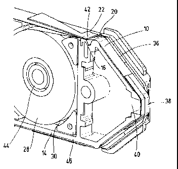
Fig. 2 shows a section of the test tape cassette according to fig. 1 in a
perspective view.
Fig. 3 shows a cassette container for the test tape cassette with a
circumferential seal in a
perspective view.
Fig. 4 shows a cassette container for the test tape cassette with a sealing
segment in a
perspective view.
Fig. 5 shows the container according to fig. 4 and 5 sealed with a sealing
foil.

CA 02650827 2008-10-30
-6-
Fig. 6 shows the container according to fig. 5 additionally with a pressing
sealing
element; and
Fig. 7 shows a strip magazine for blood sugar tests with a foil seal in an
opened
sectional perspective.
The diagnostic test units shown in the drawing allow a large number of blood
sugar
determinations to be carried out locally on blood samples taken by the
patients
themselves. In order to screen the test carriers stored as a test tape 10 or
test strips
12 from environmental influences, a container 14 is provided which has an
opening
18 the edge of which is bordered by a seal 16 and is sealed by a closing foil
22 while
keeping a passage gap 20 free to pass through the test carrier.
Fig. 1 shows a tape cassette 24 consisting of a cassette body 26 and a test
tape 10
accommodated therein. The test tape 10 is stored in the receiving chamber 30
delimited by the container 14 in the form of a supply roll 28 and can be wound
onto
a waste spool 34 while being deflected over an application tip 32 which is
accessible from outside.
As also shown in fig. 2, the test tape 10 has a thin carrier foil 36 along
which a
plurality of test fields 38 are configured spaced apart from one another. Thus
the test
fields 38 can be positioned as required in the area of the application tip 32
by
advancing the tape and body fluid (blood or optionally also tissue fluid) can
be
selectively applied there.
The test fields 38 are glued onto the carrier tape 14 as prefabricated label-
like cut-
out parts and are consequently raised above the tape. They can contain dry
reagents
which react with the analyte (glucose) while changing their colour and thus
allow an

CA 02650827 2008-10-30
-7-
optical detection. For this purpose a measuring unit in the device (not shown)
can
engage in the head region 40 of the cassette 24.
In order to protect the moisture-sensitive test chemistry over a longer
storage period,
the opening 18 of the storage chamber 30 is sealed in a material-tight manner
by the
closing foil 22 except for the passage gap 20 located over the seal 16. In the
storage
state a test field-free carrier section of the carrier tape 36 is located in
the gap area to
which the closing foil 22 can be detachably connected before first use in
order to
minimize leakages. A pressing element 42 which exerts a surface pressure on
the
closing foil 22 in the direction of the seal 16, is provided in order to
further improve
the sealing action. In this manner the carrier tape 36 which lies in between
is
pressed into the soft seal 16 which encloses and seals the rear side of the
tape.
When the tape is advanced the smooth rear side of the carrier tape 36 glides
over the
seal 16 while an elevated test field 38 that passes through runs against the
edge of
the flexible closing foil 22 and lifts the foil against the restoring force of
the
pressing element 42. The shore hardness of the seal 16 and its constructive
design,
the coefficients of friction of the materials used and the surface pressure of
the
pressing element 42 should be exactly matched to achieve a seal at a defined
withdrawal force.
The storage chamber 30 sealed in this manner can be conditioned by inserting
desiccants in order to further optimize its use. In this connection desiccant
composite injection-moulded parts can fulfil an additional function for
example as
an assisting element when inserting and positioning the tape roll 28. In
particular
bearing pins 44 or supporting parts 46 can be moulded. A high moisture holding
capacity and uptake rate can also be achieved with such compound materials.
The
storage stability before use can be further increased by a suitable outer
packaging of
the entire cassette 24 by a tight foil material.

CA 02650827 2011-01-31
-8-
As shown best in figs. 3 and 4, the opening 18 that can be closed by the
closing foil 22 is
dimensioned such that the test tape 10 in the form of a supply spool 28
including possible
desiccant-assembly functional parts can be completely inserted into the supply
chamber 30
during the manufacturing process. A rectangular opening 18 is advantageously
provided for
this purpose where the length of the opening is larger than the initial
diameter of the supply
spool and its width is larger than the width of the test tape.
In the embodiment according to fig. 3 a circumferential rectangular profile
seal 18 which is
preferably made of a TPE, is inserted into a corresponding edge recess. This
creates a flat
seal surface which simplifies the sealing with the closing foil 22 in a
material-tight manner
outside the passage gap 20.
Fig. 4 shows a modification in which a sealing segment 16 is allocated to the
tape passage
whereas the remaining border 48 of the opening 18 is formed by walls of the
container 14.
Such a structure can be manufactured in a uniform process using a two-
component
injection-moulding technique. In this connection care must be taken that a
firm tight joint is
formed during the injection process by suitable selection of materials.
The flat ring area 48 designed in this manner is heat-sealed according to fig.
5 with a closing
foil 22 along an approximately U-shaped seal strip 50. It is sealed either
only on the sealing
ring 16 (fig. 3) or on the sealing segment 16 and simultaneously on the
container material
(fig. 4). The thin flexible closing foil 22 can be formed by an aluminium foil
the inner side
of which is provided with a meltable heat seal coating. It should be ensured
that the melting
temperatures of all materials involved in the sealing process are at a uniform
temperature
level. In order to keep the passage gap 20 free, either the carrier tape 36 or
an insert of a
corresponding geometry can be sealed in during the heat-sealing process.
During the heat-
sealing a tight heat-seal joint between the container 14 or seal 16 and the
heat-sealable inner

CA 02650827 2008-10-30
-9-
side of the aluminium foil 22 is then formed on the entire surface of the seal
strip 48
with the exception of the inserted tape or insert. After the heat-sealing
process, the
carrier tape 36 which may also be adhesively joined, can be freed of slight
adhesions
by slightly transporting it forwards which is advantageously carried out when
it is
first used. If present, the insert is pulled out to thus expose the passage
gap 20.
Fig. 6 also illustrates the function of the pressing element 42. This can be
formed by
a leaf spring one end of which 52 is supported on the cassette and the free
end 54 of
which with a wide area is pressed under pretension onto the closing foil over
the
passage gap 20. A high-grade steel spring can be used to minimize material
fatigue
even under alternating climatic stress.
A variant of the invention intended for the use of test strips 12 is shown in
fig. 7.
The constructive design of the passage seal 16, 22 essentially corresponds to
the
embodiment elucidated above so that the same reference numerals are used for
the
same parts. Instead of a tape cassette, a strip magazine 56 is provided of
which only
a section is shown and comprises a rectangular storage container 14 for
holding a
stack 58 of test strips 12. Each test strip 12 has a test field 38 on a
section of a
carrier foil 36 for applying the body fluid. The stack of strips 58 is
inserted as a
complete package through the opening 18 into the container 14 before the
closing
foil 22 is sealed on and then it is sealed in while keeping the passage gap 20
free by
means of an insert. A spring mimic 60 is braced against the bottom of the
container
in order to reposition the stack towards the upper withdrawal area. In each
case the
upper strip 12 can be withdrawn by a push mechanism that is not shown by which
means the particular strip is pushed out in the longitudinal direction of the
strip
through the passage gap 20 and is provided for use. In this connection the
pressing
element 42 is only lifted to dispense the strip whereas for the remaining time
no
strip 12 is present in the passage gap 20 and thus a high degree of tightness
is
ensured.

CA 02650827 2008-10-30
-10-
The tape cassette 24 as well as the strip magazine 56 can be exchanged as
consumables in a holding drawer of a hand-held device in order to be able to
automate the test process optionally including the sampling.
In summary the following can be stated: The invention concerns a diagnostic
test
unit for analysing a body fluid comprising a test carrier (test tape 10; test
strip 12)
provided with test fields 38 for the application of the body fluid and a
container 14
containing the test carriers where an opening 18 of the container 14 is
bordered at
least in some areas by a seal 16. According to the invention it is proposed
that the
opening 18 is screened from the surroundings of the container 14 by a closing
foil
22 and that the test tape 10 or a test strip 12 to be dispensed is passed
through a
passage gap 20 between the closing foil 22 and seal 16.

Representative Drawing
A single figure which represents the drawing illustrating the invention.
Administrative Status

2024-08-01:As part of the Next Generation Patents (NGP) transition, the Canadian Patents Database (CPD) now contains a more detailed Event History, which replicates the Event Log of our new back-office solution.

Please note that "Inactive:" events refers to events no longer in use in our new back-office solution.

For a clearer understanding of the status of the application/patent presented on this page, the site Disclaimer , as well as the definitions for Patent , Event History , Maintenance Fee  and Payment History  should be consulted.

Event History

Description Date
Common Representative Appointed 2019-10-30
Grant by Issuance 2012-03-20
Inactive: Cover page published 2012-03-19
Inactive: Final fee received 2011-11-28
Pre-grant 2011-11-28
Notice of Allowance is Issued 2011-10-28
Letter Sent 2011-10-28
Notice of Allowance is Issued 2011-10-28
Inactive: IPC assigned 2011-10-14
Inactive: IPC removed 2011-10-14
Inactive: First IPC assigned 2011-10-14
Inactive: IPC assigned 2011-10-14
Inactive: Approved for allowance (AFA) 2011-09-29
Amendment Received - Voluntary Amendment 2011-07-05
Amendment Received - Voluntary Amendment 2011-01-31
Inactive: S.30(2) Rules - Examiner requisition 2010-07-30
Inactive: Acknowledgment of national entry - RFE 2010-06-17
Correct Applicant Requirements Determined Compliant 2010-06-17
Inactive: Correspondence - PCT 2010-04-29
Correct Applicant Request Received 2009-03-25
Inactive: Cover page published 2009-02-27
Inactive: Acknowledgment of national entry - RFE 2009-02-20
Letter Sent 2009-02-20
Inactive: First IPC assigned 2009-02-19
Application Received - PCT 2009-02-18
Inactive: Declaration of entitlement - PCT 2008-12-18
National Entry Requirements Determined Compliant 2008-10-30
Request for Examination Requirements Determined Compliant 2008-10-30
All Requirements for Examination Determined Compliant 2008-10-30
Application Published (Open to Public Inspection) 2007-11-15

Abandonment History

There is no abandonment history.

Maintenance Fee

The last payment was received on 2011-04-28

Note : If the full payment has not been received on or before the date indicated, a further fee may be required which may be one of the following

  • the reinstatement fee;
  • the late payment fee; or
  • additional fee to reverse deemed expiry.

Please refer to the CIPO Patent Fees web page to see all current fee amounts.

Owners on Record

Note: Records showing the ownership history in alphabetical order.

Current Owners on Record
F. HOFFMANN-LA ROCHE AG
Past Owners on Record
KLAUS SCHOTTLE
KLAUS-DIETER SACHERER
RALF STEINBRUCK
WERNER RUHL
WOLFGANG DITSCHER
Past Owners that do not appear in the "Owners on Record" listing will appear in other documentation within the application.
Documents

To view selected files, please enter reCAPTCHA code :


To view images, click a link in the Document Description column. To download the documents, select one or more checkboxes in the first column and then click the "Download Selected in PDF format (Zip Archive)" or the "Download Selected as Single PDF" button.

List of published and non-published patent-specific documents on the CPD .

If you have any difficulty accessing content, you can call the Client Service Centre at 1-866-997-1936 or send them an e-mail at CIPO Client Service Centre.


Document
Description 
Date
(yyyy-mm-dd) 
Number of pages   Size of Image (KB) 
Description 2008-10-30 10 415
Claims 2008-10-30 4 127
Drawings 2008-10-30 3 115
Abstract 2008-10-30 1 15
Claims 2008-10-31 4 129
Representative drawing 2009-02-27 1 19
Cover Page 2009-02-27 2 54
Claims 2011-01-31 4 144
Description 2011-01-31 11 473
Claims 2011-07-05 5 147
Abstract 2012-01-16 1 15
Cover Page 2012-02-28 2 56
Acknowledgement of Request for Examination 2009-02-20 1 175
Reminder of maintenance fee due 2009-02-23 1 111
Notice of National Entry 2009-02-20 1 202
Notice of National Entry 2010-06-17 1 204
Commissioner's Notice - Application Found Allowable 2011-10-28 1 163
PCT 2008-10-30 11 474
Correspondence 2008-12-18 2 84
PCT 2008-10-31 4 140
Correspondence 2009-03-25 4 202
Correspondence 2010-04-29 2 86
Correspondence 2011-11-28 2 62