Note: Descriptions are shown in the official language in which they were submitted.
CA 02651034 2008-11-03
WO 2007/131314 PCT/CA2006/000756
TITLE OF INVENTION
METHOD AND DEVICE FOR GENERATING A SIGNAL
THAT REFLECTS RESPIRATORY EFFORTS
IN PATIENTS ON VENTILATORY SUPPORT
FIELD OF INVENTION
[0001] This invention relates to assisted mechanical ventilation.
BACKGROUND TO THE INVENTION
[0002] Ventilatory assist devices are machines used in the treatment
of
respiratory failure and sleep disorders in hospital or home settings. With
assisted
ventilation (e.g. assist volume cycled ventilation, pressure support
ventilation, bi-level
assist in the case of non-invasive devices and proportional assist
ventilation)
ventilator cycles are triggered by the patient and are intended to coincide
with
patient's inspiratory effort, beginning the support when inspiratory effort
starts and
ending the support at the end of patient's inspiratory effort. In practice,
however, the
ventilator cycle never begins at the onset of patient's inspiratory effort
(trigger delay)
and the end of the ventilator's inflation phase only rarely coincides with the
end of
inspiratory effort (cycling-off errors). Figure 1 provides an example. The
bottom
channel is transdiaphragmatic pressure (measured by esophageal and gastric
catheters) and reflects true patient inspiratory effort. As may be seen,
ventilator cycle
was triggered several hundred milliseconds after onset of effort (interval
between
vertical lines) and the inflation cycle continued well beyond the effort. In
fact, the
ventilator was cycling almost completely out-of-phase with the patient.
Trigger delay
is often so marked that some efforts completely fail to trigger the ventilator
(ineffective efforts, e.g. third effort, Figure 1). A more advanced form of
non-
synchrony is shown in Figure 2. In this case, the inflation cycle of the
ventilator
extends over two patient cycles. There are, accordingly, two inspiratory
efforts within
a single inflation phase and there is an additional ineffective effort during
the
ventilator's expiratory phase. The arrows in Figure 2 indicate the location of
the extra
patient efforts that did not trigger corresponding ventilator cycles.
[0003] Non-synchrony between patient and ventilator is extremely
common.
Leung et al found that, on average, 28% of patient's efforts are ineffective
(Leung P,
Jubran A, Tobin MJ (1997). Comparison of assisted ventilator modes on
triggering,
CA 02651034 2008-11-03
WO 2007/131314 PCT/CA2006/000756
2
patient effort, and dyspnea. Am J Respir Crit Care Med 155:1940-1948).
Considering
that ineffective efforts are the extreme manifestation of non-synchrony, less
severe,
yet substantial (e.g. first two breaths, Figure 1), delays must occur even
more
frequently. Non-synchrony is believed to cause distress, leading to excessive
sedation
and sleep disruption, as well as errors in clinical assessment of patients
since the
respiratory rate of the ventilator can be quite different from that of the
patient.
Monitoring respiratory rate is a fundamental tool for monitoring critically
ill patients
on ventilators. Non-synchrony is not only prevalent in intensive care units
but is also
frequently present in the home setting during sleep when patients are
receiving bi-
level support for the treatment of sleep apnea or respiratory failure
(personal
observations). The present invention concerns a novel method and apparatus to,
non-
invasively, automatically and in real-time, generate a signal that reflects
changes in
inspiratory effort. Such a signal can then be used, among other things, to
determine
the true onset (Tonset) and end (Tend) of patient's inspiratory efforts. Such
method/device can be used simply as a monitor, informing the user of the
presence,
manifestations and magnitude of non-synchrony. The user can then take
appropriate
action to reduce the non-synchrony. Alternatively, the method/device can be
coupled
with the ventilator's cycling mechanisms, whereby onset and end of ventilator
cycles
are automatically linked to onset and end of patient's efforts, thereby
insuring
synchrony without intervention by the user.
[0004] In current ventilatory assist devices, triggering usually
occurs when
flow becomes inspiratory (i.e.>0) and exceeds a specified amount, or when
airway
pressure decreases below the set PEEP (positive end-expiratory pressure) level
by a
specified amount. Trigger delay has two components. One component is related
to
ventilator trigger response and sensitivity. Thus, if the response of the
ventilator is
poor, triggering may not occur immediately when the triggering criteria are
reached.
Alternatively, the threshold for triggering may be set too high by the user.
The
component of trigger delay attributable to ventilator response and sensitivity
is given
by the interval between zero flow crossing (arrow, Figure 1) and triggering
(second
vertical line). The response of modern ventilators has improved substantially
over the
past several years such that it is difficult to effect further improvements in
this
respect, and this invention does not contemplate any such improvements. This
CA 02651034 2008-11-03
WO 2007/131314 PCT/CA2006/000756
3
component of trigger delay can, however, still be excessive if the user sets
an
unnecessarily high threshold. This setting may be because of lack of
sufficient
expertise, or because there was excessive baseline noise at some point, which
necessitated a high threshold to avoid auto-triggering. The threshold then
remains
high even after disappearance of the noise.
[0005] The second component of trigger delay is the time required,
beyond the
onset of inspiratory effort (Tonset), for expiratory flow to be reduced to
zero (interval
between first vertical line and the arrow, Figure 1). This delay is related to
the fact
that expiratory resistance is usually high in ventilated patients and
expiratory time is
frequently too short to allow lung volume to return to FRC (functional
residual
capacity) before the next effort begins. At Tonset, therefore, elastic recoil
pressure is
not zero (DH, dynamic hyperinflation). Inspiratory effort must first increase
enough
to offset the elastic recoil pressure associated with DH before flow can
become
inspiratory, and/or before Paw (airway pressure) decreases below PEEP, in
order to
trigger the ventilator. By identifying the true Tonset, a capacity that is
permitted by
current invention, this component of trigger delay (usually the largest
component,
seen, for example, Figure 1) can be essentially eliminated.
[0006] Cycling-off errors result from the fact that, except with
Proportional
Assist Ventilation, current ventilator modes do not include any provision that
links the
end of ventilator cycle to end of the inspiratory effort of the patient. In
the most
common form of assisted ventilation, Volume Cycled Ventilation, the user sets
the
duration of the inflation cycle without knowledge of the duration of patient's
inspiratory effort. Thus, any agreement between the ends of ventilator and
patient
inspiratory phases is coincidental. With the second most common form, Pressure
Support Ventilation, the inflation phase ends when inspiratory flow decreases
below a
specified value. Although the time at which this threshold is reached is, to
some
extent, related to patient effort, it is to the largest extent related to the
values of
passive resistance and elastance of the patient. In patients in whom the
product
[resistance/elastance], otherwise known as respiratory time constant, is high,
the
ventilator cycle may extend well beyond patient effort, while in those with a
low time
constant the cycle may end before the end of patient's effort (Younes M (1993)
Patient-ventilator interaction with pressure-assisted modalities of
ventilatory support.
CA 02651034 2008-11-03
WO 2007/131314 PCT/CA2006/000756
4
Seminars in Respiratory Medicine 14:299-322; Yamada Y, Du HL (2000) Analysis
of
the mechanisms of expiratory asynchrony in pressure support ventilation: a
mathematical approach. J Appl Physiol 88:2143-2150). By providing a signal
that
reflects changes in inspiratory effort, the current invention makes it
possible to
determine when effort begins declining, thereby making it possible to
synchronize the
end of ventilator cycle with end of patient's effort.
[0007] In US patent 6,305,374 B 1 , an approach is described to
identify the
onset and end of patient's inspiratory effort during non-invasive bi-level
positive
pressure ventilation (BiPAP). This approach relies exclusively on the pattern
of flow
waveform to make these identifications. Thus, current values of flow are
compared
with an estimated value based on projections from preceding flow pattern. If
the
difference exceeds a preset amount, a phase switch is declared. There is no
attempt
whatsoever in this method to generate a signal that continuously reflects the
pattern of
inspiratory effort in real-time throughout the breath. Furthermore, while this
method
may yield reasonably accurate results in the intended application (treatment
of
obstructive sleep apnea patients with non-invasive BiPAP), a number of
considerations suggest that its use in critically ill, intubated, ventilated
patients may
not provide accurate results:
[0008] 1) Implicit to the use of flow as a marker of respiratory
muscle
pressure output is the assumption that flow pattern reflects changes in
alveolar
pressure inside patient's lung. This is where respiratory muscle pressure is
exerted.
This assumption, however, is true only if airway pressure is constant. Since
airway
pressure is one of the two pressure values that determine flow (flow=(airway
pressure-alveolar pressure)/resistance), it is clear that changes in airway
pressure can
alter flow even if there is no change in respiratory muscle or alveolar
pressure. In non-
invasive bi-level support, airway pressure, one of the two pressure values
that
determine flow, is reasonably constant during both inspiration and expiration,
even
though the absolute level is different in the two phases. If one of the two
pressure
values is constant during a given phase, it is reasonable to assume that
changes in
flow during that phase reflect changes in the other pressure, namely alveolar
pressure.
This condition does not apply in intubated, mechanically ventilated patients.
In most
modern intensive care ventilators, airway pressure is actively controlled
during
CA 02651034 2008-11-03
WO 2007/131314 PCT/CA2006/000756
expiration through adjustments of the PEEP/exhalation valve mechanism. The
pattern
of such active changes in airway pressure during expiration varies from one
ventilator
brand to another and in the same ventilator from time to time depending on the
state
of the PEEP/exhalation valve mechanism. Under these conditions, changes in
flow
trajectory during expiration cannot be assumed to reflect changes in alveolar
pressure
trajectory. Likewise, during inspiration airway pressure is far from being
constant,
regardless of the mode used. Thus, changes in inspiratory flow profile cannot
be used
to reflect similar changes in alveolar pressure. The use of flow to infer end
of effort
during the inflation phase is accordingly not plausible.
[0009] 2) When passive elastance (E) and resistance (R) are constant
over the
entire tidal volume range, the product R/E, or respiratory time constant, is
also
constant over the entire period of expiration. Because the time constant
governs the
pattern of lung emptying, a constant R/E produces a predictable exponential
flow
pattern in the passive system. With a predictable pattern it is possible to
make forward
extrapolations, or predictions, for the sake of identifying a deviation from
the
expected passive behaviour. Such deviation may then be used, with reasonable
confidence, to infer the development of an additional active force, such as
the onset of
inspiratory muscle effort. When E and R are not constant throughout the
breath, R/E
may change from time to time causing changes in flow trajectory (Aflow/At)
that are
not related to muscle pressure. Under these conditions, deviation in Aflow/At
from
previous values cannot reliably signify a change in pressure generated by
respiratory
muscles. Patients with obstructive sleep apnea, the intended population of US
patent
6,305,374 B1, have generally normal lungs; R and E are expected to be constant
over
the tidal volume range, particularly when expiratory airway pressure is higher
than
atmospheric (i.e. the usual case when BiPAP is applied). In critically ill,
intubated
ventilated patients, this is not the case. Resistance is not constant,
primarily because
these patients are intubated and the resistance of the endotracheal tube is
flow-
dependent (the higher the flow, the higher the resistance). The relation
between
resistance and flow varies from one tube to the other. Furthermore, tidal
volume in
these patients often extends into the volume range where elastance is not
constant.
Thus, as the lung is emptying, either or both elastance and resistance may be
CA 02651034 2008-11-03
WO 2007/131314
PCT/CA2006/000756
6
changing, causing changes in respiratory time constant during the same
expiration.
Under these conditions, changes in flow trajectory need not reflect changes in
respiratory muscle pressure. This considerably decreases the sensitivity and
specificity of flow pattern as a marker of inspiratory effort.
[0010] 3) Changes in respiratory muscle pressure (Fermis) are not
exclusively
used to change flow. According to the equation of motion, specifically applied
to
intubated patients:
Pmus = Volume*E + Flow*Ki + (Flow*absolute flow*K2) - Paw .......... Equation
1
[0011] Where, E is passive respiratory system elastance, K1 is the
laminar
component of passive respiratory system resistance, K2 is the resistance
component
related to turbulence (mostly in the endotracheal tube or nasal passages), and
Paw is
airway pressure which is determined by the pressure at the exhalation/PEEP
valve
(Pvalve), flow and Reõ, that is resistance of the exhalation tubing (Paw =
Pvalve -
flow*Rex). In this equation expiratory flow is negative. When P. changes, as
at
Tonset, the flow trajectory should change. However, a change in flow
trajectory also
results in changes in volume and Paw trajectories. According to Equation 1,
these
changes will oppose the change in flow. For example, if expiratory flow
decreases at a
faster rate, volume decreases at a slower rate than in the absence of Prim,.
At any
instant after Tonset, elastic recoil pressure, which is related to volume, is
higher, and
this promotes a greater expiratory flow. The same can be said for the effect
of changes
in flow trajectory on Paw trajectory; a lower expiratory flow decreases Paw,
which
promotes more expiratory flow. How much of the change in Pmus is used to
change the
flow trajectory depends on the magnitude of the opposing forces. In
particular, a
higher passive elastance and/or a higher Rex tends to reduce the fraction of
the change
in Pmus used to change flow trajectory. Furthermore, for a given P. expended
to
change the flow trajectory, the actual change in trajectory is determined by
resistance
(i.e. K1 and K2). When E, Rex, K1 and K2 are all low, a modest change in
dP./dt
results in a sharp change in flow trajectory. As these characteristics become
more
abnormal, the change in flow trajectory, for a given dPmus/dt, progressively
is
attenuated. Figure 3 illustrates this in a computer simulation.
[0012] In the example of Figure 3, respiratory muscles were inactive
in the
first second of expiration (as they usually are). This is represented by Pmus
of zero
CA 02651034 2008-11-03
WO 2007/131314 PCT/CA2006/000756
7
(lower panel). At 1.0 sec an inspiratory effort begins. Pmus rises at a rate
of 10
cmH20/sec, representative of a normal respiratory drive. The three flow
waveforms
represent, from below upwards, progressively increasing values of K1, K2, E
and Rex.
The values used in the lowest waveform are those of a patient with normal
passive
elastance and resistance, intubated with a large endotracheal tube (#9 tube,
K2=3), and
exhalation tubing with a low resistance (Rex=2). The onset of effort results
in a sharp
change in the flow trajectory that can be readily detected within a very short
time after
Tonset=
100131 The middle waveform (Figure 3) was generated with values
representing the average intensive care patient on mechanical ventilation.
Both
passive K1 and passive E are higher than normal, K2 is that of a #8
endotracheal tube,
the most common size used, and the exhalation tubing has a moderate (average)
resistance. Note that the change in flow trajectory is considerably less
pronounced. An
experienced eye, with the benefit of hindsight (i.e. observing the flow
waveform for a
substantial period after Prnõ, started), may be able to tell that a change in
trajectory
occurred at 1.0 sec. However, it is not possible to prospectively identify
that a
trajectory change took place in a timely manner, for the sake of triggering
the
ventilator. Prospective identification of a trajectory change requires
comparison
between current and previous Aflow/At values, or between current flow values
and
values expected based on forward extrapolation of the preceding flow pattern
(e.g.
dashed lines, Figure 3). There is always uncertainty with extrapolation,
particularly
with non-linear functions where the exact function is not known and, even more
so,
when the signal is noisy, as the flow signal commonly is (due to cardiac
artefacts or
secretions). Comparison of current and previous Aflow/At is also fraught with
uncertainties when the rate may change for reasons other than respiratory
muscle
action (see #1 and #2, above). Thus, a wide difference (trigger threshold)
must be
specified, between current and projected flow, or between current and previous
Aflow/At, before a trajectory change can be identified with confidence.
Otherwise,
false triggering will occur frequently. When the change in flow trajectory is
small, a
longer interval must elapse before the threshold separation is achieved. It
can be seen
from the middle flow waveform that a conservative flow separation (between
actual
CA 02651034 2013-06-21
8
and projected flow) of 0.2 1/sec would not be reached until after flow became
inspiratory. Thus, in the average mechanically ventilated patient the use of
flow
trajectory to identify Tonõt is not likely to result in a significant
improvement over the
current approach of waiting for flow to become inspiratory.
[0014] With more severe mechanical abnormalities (top waveform, Figure
3),
the change in flow trajectory is even more subtle. Even an experienced eye,
with the
benefit of hindsight, cannot distinguish between a true trajectory change and
some
flow artefact. Clearly, with a much stronger effort a flow trajectory change
may be
identifiable before flow becomes inspiratory. However, when patients have
vigorous
inspiratory efforts, there is no significant trigger delay even with current
triggering
techniques.
[0015] In summary, the use of flow to identify respiratory phase
transitions is
entirely unsuitable for identification of inspiratory to expiratory
transitions during
mechanical ventilation in critically ill patients (because of the highly
variable Paw
during inflation), and has poor sensitivity and specificity for identifying
expiratory to
inspiratory transitions in these patients because of the frequent use of
active
exhalation valves, the presence of variable time constant during expiration
and the
often marked abnormalities in elastance and resistance.
[0016] An alternative approach has recently been proposed by Younes (US
Patent Publication 2006-0249148 published November 9, 2006 and corresponding
EP
2,515,767 (WO 2003/002561); Method and Device for monitoring and Improving
Patient-Ventilator Interaction). The approach consists of generating a Pmus
waveform
using improvised values of elastance and resistance. Here, the above equation
1 is
used to generate Pmus but, instead of using real resistance (K1) and elastance
(E)
values, which are difficult to obtain in spontaneously breathing patients,
improvised
values are used which simply result in the generated Pmus waveform having the
shape
characteristics of normally occurring Pmus waveforms, namely an approximately
flat
baseline during expiration and a ramp-like rising phase in the inspiratory
phase. The
surrogate values for elastance and resistance are assigned herein, the terms
Kv and KF
to distinguish them from the real values. Once such an improvised Pmus signal
is
generated, it is possible to easily identify the onsets and ends of
inspiratory efforts for
CA 02651034 2008-11-03
WO 2007/131314 PCT/CA2006/000756
9
the sake of triggering and cycling-off ventilators. Because the Pmus generated
by
these improvised resistance and elastance values is not a real Pmus signal,
the value
generated by the current approach is referred herein to simply as Signal.
[0017] The above invention described by Younes proposes the use of a
default
value for KF and adjusting the Kv value to result in a flat baseline during
expiration.
Alternatively, a default value for Kv is used while the KF value is adjusted
to result in
a flat baseline during expiration. The preferred embodiments in this earlier
Younes
patent application employ a fixed value for one of the two variables while
adjusting
the value of the other variable manually with visual feedback from a monitor.
Although the specification suggests that appropriate values for Kv and KF may
be
selected automatically using appropriate software, the specification does not
teach any
approach for doing that and it is evident that such software would have to be
sufficiently sophisticated to replace the complex functions executed by the
eye-brain
combination in humans.
[0018] The present invention proposes new methods and apparatus to
supplement the approach proposed by Younes. These improvements relate to
methods
for automatically (as opposed to manually) determining the values of KF and Kv
required for generating a physiologically appropriate Signal waveform from
which
information about onsets and ends of inspiratory efforts can be derived.
Specifically,
these methods employ complex algorithms to distinguish between true baseline
and
noise values during expiration, a task that can be readily done by the human
eye, but
is very difficult to translate into computer instructions.
[0019] Because these new methods/device are intended to work with, and
represent an improvement over, the original Younes approach the latter
approach will
be described in some detail in the detailed description of the invention,
below.
SUMMARY OF INVENTION
[0020] In accordance with one aspect of the present invention, there
is
provided a method for generating a signal that mirrors changes in the level of
effort
exerted by respiratory muscles of patients on mechanical ventilatory support,
comprising monitoring of airway pressure (Paw), rate of gas flow (F), and
volume of
gas flow (V) of the patient; storing Paw, F and V data collected in computer
memory;
CA 02651034 2008-11-03
WO 2007/131314 PCT/CA2006/000756
generating a composite pressure signal (Signal) from:
Signal = current V*Kv + current F*KF ¨ current Paw,
wherein, KF is a coefficient that converts flow into equivalent resistive
pressure units and KF is calculated from elapsed data and selected to minimize
step changes in calculated Signal at the time of ventilator triggering and/or
cycling-off, and Kv is a coefficient that converts volume into equivalent
elastic pressure units and Kv is determined from elapsed data in a number of
steps comprising:
- scanning of F or Paw information, and/or the time derivative
thereof, during the exhalation phase of elapsed breaths and
identifying instances where the trajectory of either variable (i.e. F
or Paw) transiently reverses direction during said exhalation phase
(transients);
- selecting two or more points within the exhalation phase that are at
specified safe distances away from identified transients, and
calculating the value of Kv required to force the values of Signal
calculated at said selected points in elapsed breaths to be equal, or
nearly equal, when said selected value of KF is used as the flow
coefficient.
100211 The term F*KF may be replaced by other functions that allow for
non-
linear relation between flow and the resistive pressure units. In particular,
F*KF may
be replaced by [F*KFI + (F* absolute F*KF2)] wherein KF2 is a constant and KR
is
calculated from elapsed data and selected to minimize step changes in
calculated
Signal at the time of ventilator triggering and/or cycling off. KF2 may be
assigned a
value corresponding to the K2 constant of an endotracheal tube in place in the
patient.
100221 The values of Kv, KF, KF1 and/or KF2 may be adjusted to result
in a
specific slope as Signal during part or all of the expiratory phase.
[0023] In addition, default values of KF or KFI, depending on the
equation,
may be used to determine Signal. Alternatively, the KF or KR value, depending
on the
equation used, is a known or estimated value of patient's respiratory system
resistance. The Kv value used may be a known or estimated value of patient's
respiratory system elastance.
CA 02651034 2008-11-03
WO 2007/131314 PC T/CA2006/000756
11
[0024] Alternatively, a default value of Kv may be used while the
value of KFI
required to obtain the desired baseline Signal trajectory is obtained through
the same
steps as specified above to estimate the required Kv. In addition, the Kv
value used
may be a known or estimated value of patient's respiratory system elastance.
[0025] In the equation for determining Signal, the term V*Kv may be
replaced
by another term that allows for a non-linear relation between volume and
equivalent
elastic pressure units. The non-linear function may be of the form [fV*Kv],
wherein f
is a specified mathematical function to be applied to the volume data, or [V*
variable
Kv] and the value of Kv is a function of volume [Kv = fFv], wherein f is a
specified
mathematical function and the specified function (f) is derived from the Paw,
F and V
data measured at the selected two or more points within the exhalation phase.
[0026] The detailed transients may be classified into a number of
types by
reference to specific criteria of the type. The safe distances of selection of
the two or
more points may be set according to the transient type.
[0027] The KF required to minimize step changes in Signal may be
calculated
both at the time of ventilation triggering and time of cycling-off and, if
differences
exist between the two determinations, one or the other is chosen based on pre-
specified criteria. In this embodiment, if differences exist between the two
determinations, then a simple or weighted average value is obtained for use in
calculating Signal.
[0028] The generated Signal may be further processed to identify the
onset of
the rising phase of Signal (TONSET) and/or onset of the declining phase of
Signal
(TEND). In this procedure, the identification of TONSET may be precluded for a
specified period in the exhalation phase of the ventilator (TONSET Window
Delay)
and/or the identification of TEND is precluded for a specific period in the
inflation
phase of the ventilator (TEND Window Delay). A minimum value for TONSET Window
Delay may be specified, preferably as a function of patient's respiratory
rate.
Similarly, a minimum value for TEND Window Delay may be specified, preferably
as a
function of patient's respiratory rate. The generated TONSET and/or TEND
values
preferably was used to effect triggering and/or cycling-off of ventilator
cycles.
[0029] The generated Signal may be further processed to obtain
information
about patient-ventilator interaction and the information may be communicated
to a
CA 02651034 2008-11-03
WO 2007/131314 PCT/CA2006/000756
12
user through display on a monitor or by other forms of communication. The
information may include, but is not limited to, at least one of display of the
Signal
itself, TONSET and TEND mirrors, trigger delay, cycling-off delay, patient's
respiratory
rate and number or rate of ineffective efforts.
[0030] The calculated value of KF and/or Kv also may be communicated
to the
user through display on a monitor or by other forms of communication. This
communicated information may be accompanied by narrative/commentary providing
interpretation of the findings and/or suggestions for ventilator adjustment
that might
improve patient-ventilator interaction.
[0031] In accordance with another aspect to the invention, there is
provided a
device for generating a signal that mirrors changes in the level of effort
exerted by
respiratory muscles of patients on mechanical ventilatory support (Signal),
comprising
sensors and associated circuitry for obtaining information regarding airway
pressure
(Paw), rate of gas flow (F), and volume of gas flow (V) of such a patient;
computer
that executes the following functions:
- storing collected Paw, F and V data in computer memory;
- calculating a composite pressure signal (Signal) from:
Signal = current V*Kv + current F*KF ¨ current Paw,
wherein, KF is a coefficient that converts flow into equivalent resistive
pressure units and KF is calculated from elapsed breath data using algorithms
that calculate the KF value required to minimize step changes in calculated
Signal at the time of ventilator triggering and/or cycling-off, and Kv is a
coefficient that converts volume into equivalent elastic pressure units and Kv
is calculated from elapsed breath data in a number of steps comprising the
following functions:
- scanning of stored flow or Paw information, and/or the time
derivative thereof, during the exhalation phase of elapsed breaths
and identifying instances where the trajectory of either variable
(i.e. F or Paw) transiently reverses direction during said exhalation
phase (transients);
- selection of two or more points within the exhalation
phase that are
at specified safe distances away from identified transients, and
CA 02651034 2008-11-03
WO 2007/131314 PCT/CA2006/000756
13
calculation functions to determine the value of Kv required to force
the values of Signal calculated at said selected points in elapsed
breaths to be equal, or nearly equal, when said selected value of KF
is used as the flow coefficient
[0032] The subsidiary features of the method described above may have
corresponding apparatus features in the device of the invention.
BRIEF DESCRIPTION OF DRAWINGS
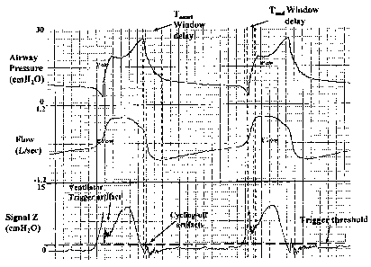
[0033] Figure 1 contains traces of airway pressure, flow and diaphragm
pressure for a patient on mechanical ventilation;
[0034] Figure 2 contains further traces of airway pressure, flow and
diaphragm pressure for ventilator cycles;
[0035] Figure 3 is a graphical representation of the effect of
variation in
certain parameters on change in trajectory of flow upon start of inspiration;
[0036] Figure 4 is a graphical representation of the effect of
variation in
certain parameters on change in trajectory of composite pressure Signal Z upon
start
of inspiration;
[0037] Figure 5 contains traces of airway pressure, flow and composite
pressure Signal Z calculated in accordance with the invention;
[0038] Figure 6 contains traces of airway pressure, flow, composite
pressure
Signal Z and diaphragm electrical activity, with the Signal Z tracing being
generated
from pressure, flow and volume tracings;
[0039] Figure 7 contains traces of airway pressure, flow, dFlow/dt and
diaphragm pressure for passive exhalation respiratory flow;
[0040] Figures 8 to 12 contain traces of airway pressure, flow,
dFlow/dt and
diaphragm pressure illustrating various type of negative flow transients
during the
exhalation phase of the ventilator;
[0041] Figure 13 contains traces of airway pressure, flow, volume,
Signal Z
for default KF, Signal Z for corrected KF and diaphragm pressure, illustrating
step
changes in calculated Signal at ventilator triggering and cycling-off;
[0042] Figure 14 is a schematic representation of the generation of
pressure
and flow signals;
CA 02651034 2008-11-03
WO 2007/131314 PCT/CA2006/000756
14
100431 Figure 15 is a photograph of a free-standing prototype that
operates
according to one preferred embodiment of the invention;
[0044] Figure 16 is a photograph of one side of the transducer board
of the
prototype of Figure 15 that generates pressure and flow inputs in the
transducer data
acquisition mode;
[0045] Figure 17 is a block diagram of the other side of the
transducer board
of the prototype of Figure 15;
[0046] Figure 18 is a block diagram of the microprocessor board of the
prototype of Figure 15 that performs the various functions;
[0047] Figure 19 is a block diagram of various real-time functions
executed
by the microprocessor on the microprocessor board of Figure 18;
[0048] Figure 20 contains traces of data produced in real-time using
the
prototype of Figure 15;
[0049] Figure 21 is a photograph of data;
[0050] Figure 22 is a block diagram of various non real-time functions
executed by the microprocessor on the microprocessor board of Figure 18;
[0051] Figures 23 and 24 contain traces of variables used to execute
non real-
time functions; and
[0052] Figures 25 and 26 are flow charts that illustrate the
classification
process for the transients.
DETAILED DESCRIPTION OF THE INVENTION
[0053] The Younes approach contemplates novel methods and devices for
specific and timely identification of respiratory phase transitions within the
patient for
use in monitoring patient-ventilator interaction or to effect switching of
ventilator
cycles. These methods/devices represent a progression in complexity that
address the
problems inherent in the prior art ventilation procedures described above.
[0054] In the simplest of these methods, a Signal is generated (Signal
X) that
incorporates changes in both the flow and airway pressure (Paw) information.
Thus,
Signal X= (Flow*Kf)- Paw ..................... Equation 2,
[0055] where, Kf is a constant that converts flow to pressure. Kf may
be an
estimated or assumed value of patient's resistance (including endotracheal
tube).
CA 02651034 2008-11-03
WO 2007/131314 PCT/CA2006/000756
There are two advantages to this approach over the use of flow alone: First,
the Signal
becomes relatively immune to changes in flow trajectory produced via changes
in
pressure at the exhalation/PEEP valve mechanism (#1 in Background above).
Thus, if
pressure at the exhalation/PEEP valve increased near the end of expiration (to
maintain PEEP), flow will decrease at a faster rate. Without the Paw
component, this
effect may appear as an inspiratory effort. With inclusion of Paw in the
signal, changes
in flow and Paw tend to cancel out. The extent to which this compensation is
complete
depends on how close Kf is to actual patient resistance. In the absence of a
known
value, a default value may be used, for example 15 cmH20/1/sec, representing
average
resistance (including ET tube) in critically ill, mechanically ventilated
patients. With
such a default value, correction is not perfect, but the signal is more
specific (than
flow) in reflecting Tonset. Second, by including Paw in the signal, the signal
incorporates that component of Prnus that was dissipated against Rex (see #3
in
Background). For example, if Paw decreases at Tonset (because of the lower
expiratory
flow), this decrease is summed with the component related to flow, resulting
in a
sharper change in Signal trajectory. With this approach, however, Signal
baseline
prior to inspiratory effort is not flat, but, as in the case of flow, rises in
a non-linear
fashion. Forward extrapolation continues to be required to identify phase
transition.
Thus, the uncertainty associated with forward extrapolation is not eliminated
but the
change in signal trajectory is sharper, resulting in a more timely detection
of Tonset for
the same selected detection threshold (i.e. difference between actual and
predicted
Signal required for identification). Furthermore, this approach continues to
be
unsuitable for detection of inspiration to expiration transitions (Tend).
[0056] A further improvement is achieved by incorporating a component
related to volume in the Signal (Signal Y). Thus:
Signal Y= Volume*K, + Flow*Kf - Paw .................... Equation 3,
[0057] where, Kv is a factor that converts volume to pressure. With
this
treatment, the increase in the flow term during expiration (note that flow is
negative)
is offset by the decrease in the volume term. This tends to linearize, and
decrease the
slope of (flatten) the Signal in the interval prior to Tonset, reducing the
uncertainty
associated with extrapolation, while the change in trajectory at Tonset is
rendered more
acute on account of incorporating representation of all actions resulting from
the
CA 02651034 2008-11-03
WO 2007/131314 PCT/CA2006/000756
16
change in Prnõ, (see #3 in Background). In the best case scenario, where Kv is
identical to passive elastance, Kf is identical to passive resistance, and
there are no
non-linearities in the passive pressure-flow and pressure-volume relations,
Signal Y
would be identical to the actual Pmõs waveform, with a flat baseline and a
crisp rising
phase at Tonset (i.e. as in the Pim', panel of Figure 3). Under these
conditions,
extrapolation is unnecessary, and phase transition is identified when Signal Y
exceeds
a set threshold above the baseline value, to account for random baseline
noise.
Unfortunately, however, precise determination of actual passive properties
during
assisted ventilation is impossible, and there are non-linearities in the
pressure-flow
and pressure-volume relations. These result in some instability in baseline,
necessitating the use of extrapolation. It may be expected, however, that the
transition
from baseline to active inspiration will be crisper after including a volume
component
(see below).
[0058] A further improvement is achieved by allowing for non-linearity
in the
pressure-flow relation. In intubated patients, the non-linear element is
almost
exclusively due to endotracheal tube characteristics. In patients on non-
invasive
support non-linear behaviour is related to the pressure-flow characteristics
of the nose.
Thus, in either case, it is desirable to allow for non-linear relation between
flow-
related (i.e. resistive) pressure losses and flow. Thus, a suitable alternate
approach is
to partition the flow component in two parts, one related to the endotracheal
tube or
nasal passages and the other related to a laminar component of resistance
(Kf). Such
Signal is referred to as Signal Z. Thus:
Signal Z = Volume*K, + Flow*Kf + (Flow*absolute flow*Ke) - Paw Equation 4,
[0059] where Kf2 may be the commercially available K2 value of the
endotracheal tube in place or an estimate of the K2 value of nasal passages.
This
treatment essentially eliminates any artifactual baseline instability related
to non-
linear pressure-flow behaviour, further reducing the need for extrapolation
and
enhancing the crispness of the transition. It should be pointed out that the
above
approach of replacing [flow*KF1 by [flow*KR + (Flow*absolute flow*KF2)] is
only
one of many possible approaches to allow for non-linear behavior between flow
and
pressure. Other non-linear functions, for example exponential or power
function, may
be used and provide equally satisfactory solutions in the intended
applications. For
CA 02651034 2008-11-03
WO 2007/131314 PCT/CA2006/000756
17
example, one may choose instead to have KFi increase in a specified way as a
function of flow [KFI=flow*K] where K is a default value or a value that is
determined from analysis of pressure and flow data. Other possible functions,
e.g. KF1
being an exponential or power function of flow, may be used. Alternatively,
KFI may
remain as a constant but flow itself is modified according to a specified
function. For
example, the term [flow*KFi] is replaced with [fflow*KFi] where KFI is a
constant
and f is an appropriate function of flow. In all these alternative approaches,
the
appropriate function to be used may be empirically specified or be determined
by use
of appropriate regression equations to fit the relation between pressure and
flow
obtained independently in the patient. Thus, although in the preferred
embodiment
non-linear behavior between flow and pressure is modeled as in equation 4
[resistive
pressure = Flow*KFi+ (Flow*absolute flow*KF2)], other functions are possible
and
their use is within the scope of the present invention.
[0060] As indicated earlier, precise estimates of E and K1 are
impossible to
obtain during assisted ventilation. Passive E and R (including KO may be
available
from earlier determinations in which the patient was made passive. These
values may
be different from the current values, either because the ventilation
conditions under
which measurements were made were different, or true E and R (i.e. KO may have
changed in the interim. Some techniques can be used to estimate E and R during
conventional assisted ventilation, but these are not very reliable. An
important issue,
therefore, is the impact of differences between the Kõ and real E, and between
Kf and
real resistance, on the baseline of the generated signals and on the sharpness
of the
transition.
[0061] In Figure 4, the same Prnus waveform shown at the bottom of
Figure 3
was used to generate flow, volume and Paw waveforms using values
representative of
the average patient (K1=10, K2=5.5, E=25, Rex=5, similar to the values used to
generate the middle flow panel of Figure 3). Signal Z was then generated from
the
resulting flow, volume and Paw waveforms using inaccurate values of K, and Kf
(i.e.
K.õ different from real E and Kf different from true KO. Simulations were made
with
errors in either direction (over- or underestimation) of a magnitude that
reflects
CA 02651034 2008-11-03
WO 2007/131314 PCT/CA2006/000756
18
reasonable outside limits of such errors in practice (i.e. E and K1
overestimated by
100% or underestimated by 70%).
[0062] As may be expected, when there are no errors (i.e. Kv=E and
Kf=K1,
middle line, Figure 4), Signal Z is identical to the actual Prnus waveform.
However,
when there are differences between assumed values and actual values, the
baseline,
prior to T.et, is neither flat nor linear. When Kv is >E, or Kf is < K1 (upper
two lines),
baseline is sloping down. Under these conditions, there is a qualitative
change in
direction of Signal Z at Tonset of effort. Such a directional change can be
easily
detected (e.g. by differentiating Signal Z and looking for the point at which
the
differentiated signal becomes positive). However, when Kv is <E, or Kf is > K1
(bottom two lines, Figure 4), baseline is sloping up and Tonset is evident as
a change in
slope; a quantitative, as opposed to the qualitative, difference observed with
the
opposite errors. To identify inspiratory effort under these conditions, as in
the case of
flow (Figure 3), requires forward projection or extrapolation with the
attendant
increase in uncertainty and the necessity to increase trigger threshold. It
should be
noted, however, that with this approach (i.e. using Signal Z (or Y) as opposed
to flow)
the change in trajectory is much sharper than in the case of flow (middle
line, Figure
3), making it possible to identify inspiratory effort sooner. It should also
be noted that
the upward slope of the signal, once effort begins, is related to the Kf
value, being
higher when Kf is higher than K1, and vice versa.
[0063] It follows that the use of known values of E and K1, obtained
from
previous direct measurement, offers advantages over the use of flow. However,
under
some conditions (i.e. baseline sloping upward) extrapolation techniques (or
comparisons between current and previous rates of Signal change) are required,
and
this may delay detection of phase transition.
[0064] A further novel aspect of the Younes invention is to completely
ignore
patient values of E and K1 and to simply select empiric values of Kv and Kf
that result
in a flat or slightly downward sloping baseline in the latter part of
expiration. It is
clear from Figure 4 that, with respect to baseline pattern (i.e. pattern prior
to
inspiratory effort), errors can be made to cancel out. Thus, overestimation of
E and
overestimation of K1 produce opposite errors. If empiric values of Kv and Kf,
that
may have no bearing on actual values, are used, the baseline may be sloping up
or
CA 02651034 2008-11-03
WO 2007/131314 PCT/CA2006/000756
19
down depending on the nature and magnitude of errors. Even though one cannot
tell
which value is in error, or by how much, it is always possible to obtain a
flat baseline
by adjusting either Kf or K. For example, if using the empiric values results
in an
upward sloping baseline, the baseline can be made flat by increasing the
empiric Kv or
decreasing the empiric Kf. If such adjustments result in a flat baseline but
some
systematic non-linearities persist, these can be offset by adjustments of the
non-linear
Kf2 term, if Signal Z is used, resulting in a flat, and linear baseline. Under
such
conditions, identification of Tonset presents little difficulty. A
particularly suitable
approach for generating Signal Z is to use a default Kf value of 10
cmH20/1/sec (15 if
Signal Y is used) and adjust Kv to obtain a flat Signal baseline.
Alternatively, a default
Kv value (e.g. 25 cmH20/1, representing average elastance in ICU patients) is
used
and Kf is adjusted to obtain a flat Signal baseline. The former approach was
found
preferable by the inventor as it guarantees a fairly brisk rate of signal rise
at Tonset.
Adjustments of Kv at a set Kf, or vice versa, can be implemented by the user
employing external inputs for Kv and/or Kf, with feedback from a graphic
display of
the generated Signal (Signal Y or Z). Alternatively, selection of the optimum
Kv and
Kf values may be done automatically using appropriate software, as in the
present
invention.
[0065] The above approach does not address the possibility of non-
linear
relation between volume and elastic pressure losses, i.e. Kv is not a
constant. When
this is present, and it is common in mechanically ventilated patients, the
respiratory
system is stiffer in the higher part of the tidal range. When Kv, which is a
constant, is
adjusted to produce a flat or slightly decreasing Signal in the latter part of
expiration
the Signal is not flat in the early part of expiration. In the presence of non-
constant
elastance (higher elastance at higher volumes) the Signal shows a rising phase
in the
early part of expiration that continues until volume reaches the range of
constant
elastance. This artifactual rising phase may cause false identification of a
new
inspiratory effort. This problem may be averted by "blinding" the Tonset
detection
circuitry to the Signal during the early part of expiration. This can be done,
for
example, by gating the Signal to the Tonset detection circuitry only after a
certain delay
from onset of expiratory flow (Tome window delay). Alternatively, the Tonset
detection
circuitry may continue to detect Tonset during this period but the resulting
CA 02651034 2008-11-03
WO 2007/131314 PCT/CA2006/000756
identification is gated out during this period. Detection of these false
triggers can be
easily recognized visually by their consistent relation to end of ventilator
cycle. The
magnitude of the delay (blinding or blanking period) can then be adjusted
accordingly. Alternatively, software algorithms can be developed to detect
triggering
Signals with a consistent relation to end of ventilator cycle and
automatically
adjusting the width of the window.
[0066] The approach of blinding the Tonset detection circuitry to the
signal
over a time zone close to ventilator cycling-off, where flow is changing
rapidly, also
helps weed out false triggers related to other artifacts that commonly occur
in the
Signal at this time (see Cycling-off Artifacts, Figure 5). These are related
to
acceleration pressure losses, which are difficult to compensate for, or to
phase delays
between pressure and flow signals, which are common in this setting, among
other
factors.
[0067] An alternative (or complimentary) solution to the issue of non-
linear
relation between volume and elastic pressure is to use a non-constant value
for Kv.
For example, Kv may itself be a function of volume. A variety of functions may
be
used. For example, Kv may rise linearly with volume (Kv=V*constant).
Alternatively,
Kv may be constant up to a certain volume and then increase linearly with
volume
above this level. Kv may also be made to rise exponentially or as a power
function of
volume above a specified volume. Alternatively, the term V*Kv may be replaced
with
[fV*Kv] where Kv is a constant and f is an appropriate function of volume. The
appropriate function may be empirically specified or be determined by use of
appropriate regression equations to fit the relation between pressure and
volume (see
below).
[0068] It should be pointed out that the selected values of Ic and Kf
may have
little to do with actual patient elastance and resistance. These values are
simply used
to facilitate detection of phase transitions.
[0069] Figure 6 shows an example of Signal Z generated from pressure,
flow
and volume tracings. The Signal was generated using a default Kf- of 10, Kf2
of 5.5
(ET tube #8) and a Kv of 30.5 selected because it produced a flat baseline in
the latter
part of expiration. Note the flat baseline of Signal Z in the latter part of
expiration. In
CA 02651034 2008-11-03
WO 2007/131314 PCT/CA2006/000756
21
this patient, diaphragmatic electrical activity was also monitored (lowest
tracing), and
this reflects the activity of the main inspiratory muscle. Note the excellent
agreement
between the onset of effort identified from the Signal Z (arrows) and the
onset of
diaphragm electrical activity. Note also that Tonset (arrows) was identified
much earlier
than the time at which the ventilator triggered with a conventional triggering
algorithm (Ttrigger, top channel, Figure 6).
[0070] A number of approaches can be used to identify a change in
Signal
trajectory indicative of E-->I transition (Tonset). Some of these include:
a) Differentiating the Signal (ASignal/At) and comparing current values
with values obtained earlier. Tonset is identified when the difference
exceeds a specified amount.
b) Comparing current values of Signal with predicted values obtained
from forward projection of previous Signal trajectory. Tonset is identified
when the difference exceeds a specified amount.
c) Comparing current values of Signal with values obtained earlier. Tonset
is identified when the difference exceeds a specified amount.
d) Preferred approach: Differentiating the Signal (ASignal/At) and
identifying points where ASignal/At crosses zero in a positive direction
(to(+)). The change in Signal amplitude, relative to amplitude at the
immediately preceding to(+), is continuously calculated. Tonset is
identified when the difference between current value and value at the
preceding to(+) exceeds a specified amount (threshold). If the difference
does not reach threshold by the time ASignal/At crosses zero in a
negative direction (to(-)), the difference is reset to zero, until the next
to(+). This approach has the advantage of filtering out slow, random
undulations in baseline Signal without altering the relation between
Signal and inspiratory effort (which would occur if a simple high pass
filter were used). Such slow, random undulations in baseline Signal
may be produced, for example, by changes in thoracic blood volume,
imperfect compensation for mechanical non-linearities, or random
changes in respiratory muscle tone unrelated to phase transitions. The
CA 02651034 2008-11-03
WO 2007/131314 PCT/CA2006/000756
22
same approach can also be used to estimate the amplitude of higher
frequency baseline noise (e.g. due to cardiac artifacts or secretions, see
below). Such information can then be used to automatically adjust the
threshold for identifying Tonset.
[0071] Regardless of which approach is used to identify Tonset (a-d,
above, or
other approaches), a threshold must be set for the magnitude of change that
must be
reached for Tonset to be declared. Several methods can be used to select such
threshold.
Some of these include:
i) A fixed threshold is arbitrarily selected. For example, with approach
(d), a Signal increase, beyond the latest to(+), of 2 cmH20 may be
used under all conditions. Appropriate values may be chosen for other
approaches. Although feasible, when a universal threshold is used, the
value must be sufficiently high to avoid false auto-triggering under all
circumstances. Since noise level varies from patient to patient, and
from time to time, such a universal threshold would have to be set to
a level that is unnecessarily high under most conditions.
ii) Threshold may be individually selected by the user via external
controls. This can be achieved by the user selecting a value that
results in minimal auto-triggering. Alternatively, with the help of
graphical display of the Signal, the user may adjust the threshold
above baseline noise level (e.g. horizontal dashed line, Figure 5).
iii) Software algorithms can be developed to distinguish noise from
efforts and automatically adjust the threshold accordingly.
[0072] The preceding account focussed primarily on identification of E-
->I
transitions. However, once Kõ and Kf are selected to produce a nearly flat
baseline
during expiration, the shape of the Signal during inspiration provides a
reasonable
approximation of the shape of inspiratory muscle output (Pmus) (for example,
see
Figure 6). End of inspiratory effort (Tend) is normally defined as the point
at which
inspiratory muscle output rapidly declines from its peak value. To implement
this
definition, the highest value of Signal Y (or Z) during the inflation phase
can be
identified, in real time, using any of a number of standard techniques. Tend
is
CA 02651034 2008-11-03
WO 2007/131314 PCT/CA2006/000756
23
identified when the Signal decreases below a specified value or a specified
fraction of
peak value.
[0073] At times, the Signal undergoes a transient artifactual
reduction soon
after ventilator triggering. An extreme example is shown in Figure 5 (arrow
indicating
Ventilator Trigger Artifact). It is recognized as an artifact, as opposed to
natural end
of effort (Tend), because the Signal resumes rising again. The presence of
these
artifacts may cause false identification of Tend. To avoid this, the Tend
identification
circuitry is "blinded" to the Signal for a set period after Tti
gger (see Tend Window
Delay, Figure 5) in the same way the Tonõt identification circuitry is
"blinded" to the
Signal soon after ventilator cycling-off. Distinction between artifactual and
true Tend
can be easily made by the consistent occurrence at Ttrigger and the secondary
rise in
Signal that characterize false Tends. The distinction can be made by the user
with the
help of a monitor displaying the Signal, or by using software algorithms. The
width of
the Tend Window delay is adjusted accordingly. Alternatively, the width of the
Tend
Window Delay may be set to insure that the ventilator's inflation phase is not
less
than an appropriate physiological fraction (e.g. 30%) of the patient's
respiratory cycle
duration (Tug). For example, if the patient's respiratory rate is 20 (i.e.
TToT=60/20 or
3 seconds), a Tend Signal may be precluded from cycling off the ventilator
until 0.9
second (30% of 3 seconds) had elapsed since Tonset=
[0074] One aspect of the present invention concerns a process to
automate the
selection of a Kv value that results in a stable Signal baseline during the
expiratory
phase. The basic approach is to identify periods during the expiratory phase
of the
ventilator that are free of any evidence of real or artifactual pressure
generation by the
respiratory muscles. Since, by definition, the remaining periods (effort-free
periods)
are "passive", Signal values calculated at different points during these
effort-free
periods should be the same. Thus, by identifying effort-free periods within
the
ventilator's expiratory phase and sampling pressure, flow and volume at
different
points within these periods it is possible to calculate the Kv value required
to "force"
Signal to be the same in between efforts, thereby resulting in a stable Signal
baseline.
As an example, taking the case where Paw, flow and volume were sampled at only
two
effort-free points (points a and b) during the ventilator's expiratory phase
and
applying equation 4 at both points one obtains:
CA 02651034 2008-11-03
WO 2007/131314 PCT/CA2006/000756
24
Signal Z(a)= V olume(a)*Kv + Flow(a) *KFI + (Flow(a) *abs flow(a) *Kf2) -
Paw(a) AND,
Signal Z(b) = Volume *Kv + Flow(b) *KFI + (Flow *ohs flow(b) *K2) - Paw(b)
[0075] To
establish a flat baseline for Signal Z one dictates that Signal Z(a) =
Signal Z(b). From this, the value of Kv required to obtain a flat baseline
between
efforts at a given KR can be derived. Thus:
Kv = [(Paw(a) - Paw(b))
(FlOW(a) FlOW(b))*Kpi ¨ ((Flow(a)*abs flow(a)) - (Flow(b)*abs
flow(b)))*KF2] / (Volume(a) - Volume) Equation 5
[0076] It
must be emphasized that one need not insist on Signal being
identical at the two points of measurement. Under some circumstances, it may
be
desirable to have Signal baseline sloping upward or downward by specified
amounts.
To effect this, one dictates that Signal at "a" should be different from
Signal at "b" by
a specified amount, X, where X may be a constant (e.g. Signal Z(a)= Signal 4+
2)
or a function of time difference (dT) between the two points (e.g. Signal
Z(a)= Signal
2*dT). Thus, the above approach may be used to produce any desirable slope of
Signal baseline, including a flat baseline (zero slope).
[0077] It is
clear that there are several other possible procedural and
mathematical ways by which specified baseline slopes of the composite Signal
can be
obtained once the effort-free periods have been identified. For example,
instead of
solving for the required Kv at a given Kn, the value of KFi required to obtain
a flat
baseline between efforts at a given Kv can be derived. Thus:
KF1 = [(Paw(a) - Paw(b)) ¨ (Volume(a) - Volume(b))*Kv ¨ ((Flow(a)*abs flow(a))
-
(Flow(b)*abs flow(b)))*KF21 / (Flow(a) - Flow(b)) Equation 6
[0078] In
such a case, the Kv value used may be a default constant value (e.g.
25, reflecting the average elastance in ventilated patients, personal
observations) or an
independently measured elastance value.
[0079]
Similarly, instead of measuring Paw, flow and volume at only two
effort-free time points, one may choose to measure these variables at three or
more
effort-free points and obtain the required value of Kv by regression analysis.
One
form of regression analysis that is suitable in this case is:
X = Y.Kv
[0080]
where, X values are the numerator values in equation 5 obtained from
differences between Paw, flow and volume at the different points of sampling
and the
CA 02651034 2008-11-03
WO 2007/131314 PCT/CA2006/000756
corresponding values obtained at earlier sampling points, and the Y values are
the
corresponding volume differences. For example, if samples were obtained at
four
effort-free points (1 to 4) during the exhalation phase one X,Y set may be
obtained
from differences between points 1 and 4, another from differences between
points 2
and 4, and yet another from differences between points 1 and 3, and so on for
a
maximum number of X,Y sets of 6. Other types of regression analysis methods
can be
used to arrive at the best-fit Kv for the effort-free samples.
[0081] As indicated earlier, one may choose to use a non-constant Kv
to allow
for non-linear relation between volume and pressure. To implement such a non-
linear
behavior, one may use a best-fit non-linear function (e.g. exponential, power.
.etc) to
fit the X and Y data. Or, one may use other statistical approaches to arrive
at a
suitable description of the relation between the pressure (numerator product
in
equation 5) and volume (denominator product in equation 5) data collected
during the
exhalation. Thus, although the preferred embodiment employs a constant Kv, it
is to
be recognized that the use of non-constant Kv is also feasible and such use is
within
the scope of the present invention.
[0082] Likewise, the same approach can be employed utilizing Equation
3 in
place of Equation 4. Thus, the novelty of the present invention is not in how
to
process the Paw, flow and volume data obtained at effort-free points but in
the general
approach of deriving the required Kv or KF1 values by sampling pressure, flow
and
volume in effort-free periods during exhalation and how to identify these
effort-free
periods. This will now be discussed in detail.
[0083] One aspect of the present invention is a method for identifying
effort-
free periods that are suitable for sampling Paw, flow and volume for the sake
of
estimating Kv. This method is based on the fact that in a totally passive
(i.e. effort-
free) exhalation expiratory flow reaches its peak (most negative) value early
in the
expiratory phase and declines progressively (i.e. becomes less negative) as
exhalation
continues (Figure 7). Accordingly, the first derivative of flow (dFlow/dt) is
positive
throughout the expiratory phase, except for very minor noise artefacts (Figure
7). The
present approach is based on the presumption that occurrence of a significant
negative
dFlow/dt transient during the ventilator's exhalation phase (i.e. trajectory
of
expiratory flow changing direction from rising (becoming less negative) to
falling
CA 02651034 2008-11-03
WO 2007/131314 PCT/CA2006/000756
26
(becoming more negative) as exhalation progresses indicates that an event has
happened, or is happening, that violates the passive state. Accordingly,
sampling of
Paw, flow and volume should be avoided within an appropriate region in the
vicinity
of such transients.
[0084] There are several types of events that may violate the passive
state
during the exhalation phase of the ventilator. These are shown in Figures 8 to
12.
Figure 8 illustrates the case where the inspiratory effort that triggered a
previous
ventilator cycle extended beyond the inflation phase into the exhalation phase
(type 1
negative flow transient). Here, the ventilator inflation phase terminated
before the end
of inspiratory effort with the consequence that the decline in inspiratory
effort
(diaphragm pressure) occurred in the early exhalation phase instead of prior
to
beginning of exhalation phase (compare with the next breath in Figure 8). As a
result
of the withdrawal of a distending force during exhalation, expiratory flow
became
transiently more, instead of less, negative, resulting in a negative dFlow/dt
transient of
a substantial amplitude and duration.
[0085] Figure 9 shows another type of negative flow transient (type 2
transient). Note that expiratory flow increased at the arrow without a
preceding
inspiratory effort (note that diaphragm pressure was flat prior to onset of
the negative
flow transient) or a decrease in Paw at the time (in fact Paw increased during
the
negative dFlow/dt transient, which should have decreased expiratory flow). The
only
possible explanation for this type of transient is expiratory muscle
recruitment.
[0086] Figure 10 shows negative flow transients due to ineffective
inspiratory
efforts (type 3 transient). Here, inspiratory efforts occurred (note the
positive
deflections in diaphragm pressure) during the ventilator's expiratory phase in
the 2nd
and 3rd illustrated breaths. The distending force of the inspiratory effort
caused a
reduction in expiratory flow but failed to trigger the ventilator (see also
Figures 1 and
2). As the effort subsided later, the distending pressure decreased, resulting
in a
secondary increase in expiratory flow.
[0087] Figure 11 shows a negative flow transient caused by coughing
effort
(type 4 flow transients). As in ineffective efforts, the increase in
expiratory flow
(negative dFlow/dt transient) is preceded by an inspiratory effort (arrow in
diaphragm
pressure) but, unlike ineffective efforts and other negative transients,
dFlow/dt
CA 02651034 2008-11-03
WO 2007/131314 PCT/CA2006/000756
27
reaches much more negative values (it was ¨5.2 in the illustrated example)
and,
characteristically, there is a large positive overshoot in the dFlow/dt signal
immediately following the negative transient (cf. Figures 8 to 10).
[0088] A number of other events that, unlike the previous four
categories, are
not related to organized respiratory acts can also produce transient increases
in
expiratory flow (negative dFlow/dt transients) during the ventilator's
exhalation
phase. These may result from biological or mechanical/electrical noise. The
most
common in the biological noise variety are cardiac artefacts which can, at
times, result
in substantial oscillations in flow (e.g. Figure 12). Because heart rate is
substantially
higher than respiratory rate, the interval between successive transients of
this type is
less than what is expected with respiratory efforts (Figure 12). Other causes
of
biological noise include erratic twitching in the diaphragm (e.g. hiccups)
that can be
recognized by their brief duration and occurrence at an unexpected time
relative to
previous or succeeding inspiratory efforts. In the mechanical noise category
are
vibrations in the flow signal produced by secretions, by the gas delivery
system or by
transient oscillations in the exhalation valve assembly. At times the flow
signal is also
contaminated by electrical noise. When these non-respiratory transients are of
modest
amplitude they do not appreciably affect estimates of Kv and can, accordingly,
be
ignored for the sake of this application. However, at times the artefactual
change in
flow can be sufficiently large as to materially alter Kv estimates. Thus,
these artefacts
may be conveniently divided into "significant", herein called type 5
transients (e.g.
Figure 12), or "insignificant", herein referred to as type 6 artefacts (e.g.
Figures 7 to 9
and 12).
[0089] Accordingly, in this aspect of the invention, the ventilator
exhalation
phase is scanned for the presence of instances where expiratory flow
transiently
increases (negative dFlow/dt transients).
[0090] Except in cases where the pressure at the exhalation valve is
actively
controlled, airway pressure (Paw) during the exhalation phase of the
ventilator is the
mirror image of exhaled flow. This is because when downstream pressure (i.e.
at the
exhalation valve in this case) is nearly constant, upstream pressure (Paw in
this case)
will vary directly as a function of exhaled flow. In essence, the exhalation
tubing
functions as a flow meter. In this case, Paw can be used as a surrogate for
flow for the
CA 02651034 2008-11-03
WO 2007/131314 PCT/CA2006/000756
28
sake of identifying transients that may signify efforts during the exhalation
phase.
Note, for example, that whenever there is a negative flow transient in Figures
8 to 12
there is a corresponding transient in the Paw tracing but the polarity is
opposite since
an increase in expiratory flow (i.e. more negative flow value) is associated
with a
more positive Paw value. Thus, while the in the presently preferred embodiment
we
have utilized changes in flow to identify transients suggesting efforts or
undesirable
forces during the exhalation phase, Paw can be used instead of flow for this
purpose.
However, in this case one would be looking for positive (as opposed to
negative) Paw
transients where trajectory changes direction from negative (declining Paw) to
positive. Likewise, whereas the classification of type of transient, to follow
immediately below, is based on flow information, it could easily be adapted
for use
with Paw instead. Accordingly, in this aspect of the invention,
identification/classification of transients for the sake of identifying effort-
free periods
may be done using either flow or Paw information.
[0091] In another aspect of the invention, identified transients are
classified as
insignificant, and may be ignored, or significant and, hence, to be avoided in
the
sampling procedure. This classification process can be simple or complex
depending
on the circumstances in which this methodology is applied. In its simplest
form,
minimum dFlow, dFlow/dt and/or duration or other criteria may be specified to
distinguish between significant and insignificant transients. At the other
extreme,
criteria are set for identifying each type of transient separately (types 1 to
6 above).
While clearly more cumbersome and demanding, by defining the cause of the
transient this latter approach has a number of advantages: a) It would make it
possible
to obtain useful data (for the sake of estimating Kv) from many breaths that
contain
significant transients. This is because once the cause is established, it
becomes
possible to set "safe" time regions within the same breath based on known
characteristics of such a cause. For example, with a type 2 transient (phasic
expiratory
muscle recruitment) it would still be "safe" to sample data in the region
preceding the
transient, whereas with type 3 transient (ineffective effort) it would be safe
to sample
after the end of the transient but a substantial region before the transient,
representing
the period of the preceding inspiratory effort (Figure 10), must be avoided.
With the
simple approach, which does not identify the specific cause of the transient,
one might
CA 02651034 2008-11-03
WO 2007/131314 PCT/CA2006/000756
29
have to exclude all breaths that contain significant transients on the grounds
that one
cannot be sure where to sample data relative to the transient. b) By
identifying
specific causes of the negative transients, it would be possible to provide
the user with
useful ancillary information, for example presence and number of ineffective
efforts
(type 3 transients), presence of expiratory muscle recruitment (type 2
transients),
inadequate inflation time (type 1 transients)...etc.
[0092] The preferred embodiment to be described below incorporates
criteria
for selectively identifying each of the six types of transients. These
criteria were
developed based on known physiological characteristics of the different causes
of
such transients and on observations of numerous examples of each kind where
the
specific cause could be identified with certainty (e.g. where concurrent
recordings of
esophageal and/or gastric pressures were available). The criteria to be
described in the
preferred embodiment reflect certain boundaries for transient characteristics,
and
associated changes in other signals, that were found, through trial and error,
to offer a
reasonably good separation between the various types of transients. It is to
be
recognized that these are only guidelines based on experience so far, which
can be
modified or expanded in the future. For example, it may prove useful or
convenient to
use a different classification of the transients by combining different types,
splitting a
given type into subtypes, or introducing new types. It may also be possible to
use
different quantitative criteria or different associated changes in other
signals to effect
the separation of different types. It should also be recognized that the
criteria specified
in the preferred embodiment were derived from signals processed in a specific
way. A
change in the signal processing methods would necessitate changes in the
separation
criteria. For example, a minimum reduction in dFlow/dt of 1.0 1/sec/sec for
identifying a type 5 transient is based on the use of a smoothing interval of
100 msec
in the processing of the dFlow/dt signal. The critical dFlow/dt value would be
different if one uses a longer or shorter smoothing interval, and so on. For
these
reasons, the patent claims relating to this aspect of the invention do not
specify the
number of transient types to be considered or the specific characteristics
that
distinguish each. Rather, the claims relate to a general approach comprising
the
detection of negative flow transients during the exhalation phase of the
ventilator and
CA 02651034 2008-11-03
WO 2007/131314 PCT/CA2006/000756
their classification into different types based on specified criteria of said
transients
and in other monitored or derived signals.
[0093] Another aspect of the invention relates to a decision process
for
selecting time regions during the ventilator's exhalation phase in which to
sample Paw,
flow and volume for the sake of estimating Kv by use of any of the
mathematical
approaches outlined earlier. Again, this decision process may be simple or
complex
depending on circumstances of use. In the simplest approach, sampling is
avoided
entirely in any expiratory phase containing a significant negative transient
of any
kind. Particularly when significant negative transients are very frequent, for
example
cardiac artefacts or when ineffective efforts are very frequent, this approach
would
limit the number of breaths from which useful data can be obtained. In some
cases, it
may not be possible to find suitable breaths for long periods. A preferred
approach is
to identify regions to avoid in the vicinity of the negative transients and to
sample
outside these regions. As indicated earlier, the specific type of the
transient will
dictate the location of the safe regions. In the preferred embodiment, I have
used/specified certain time boundaries around each type of transient that are
to be
avoided. These are based on the following considerations and on numerous
observations of the pattern of respiratory muscle pressure output in the
vicinity of
these transients:
[0094] Type 1 transient (Figure 8): It is safe to sample in the
interval beyond
the end of the negative transient subject to exclusions dictated by other
transients
(note that diaphragm pressure reaches baseline soon after the end of the
negative
dFlow/dt transient, Figure 8).
[0095] Type 2 transient (Figure 9): This transient indicates active
expiratory
pressure generation. Sampling Paw, flow and volume in the presence of a
changing
expiratory pressure would corrupt the Kv value. Because once phasic expiratory
pressure generation begins it is usually maintained until the onset of the
next
inspiratory effort, it is recommended that the entire period beyond the onset
of the
negative transient (the presumed onset of expiratory pressure) be avoided. The
region
preceding transient onset may be sampled from, however, subject to exclusions
dictated by other transients.
CA 02651034 2008-11-03
WO 2007/131314 PCT/CA2006/000756
31
[0096] Type 3
transient (Figure 10): The onset of a type 3 transient indicates
the point at which an ineffective inspiratory effort begins declining.
Therefore, in
order to sample data that are free of inspiratory pressure it is necessary to
avoid a
period extending from well before the onset of the transient, reflecting the
estimated
duration of the rising phase of the effort, to well after the onset of the
transient to
exclude the period of the declining phase of Pmus. In my experience with
several
thousand documented ineffective efforts, the duration of the rising phase
varies
considerably from 0.3 to 1.0 sec and the declining phase of the effort rarely
extends
beyond the end of the negative transient (Figure 10). Because the duration of
the
rising phase is highly variable, it is preferable to individualize the
excluded zone
preceding the transient based on the likely onset of the rising phase of the
transient in
question. Accordingly, in the preferred embodiment, a procedure is described
whereby the lowest Signal value preceding transient onset is identified.
Decisions as
to the extent of the excluded zone are based on Signal level at this point
relative to a
previously identified minimum (see Preferred Embodiment). Clearly, expanding
the
region to be avoided would be a more conservative approach that covers
instances
where the rising and declining phases are longer than anticipated. However,
expanding the avoidance region decreases the chance of obtaining useful data
in
patients who have many ineffective efforts.
[0097] Type 4
transients (Figure 11): Coughing is a substantial event that has
consequences that outlast the event itself. For this reason, in the preferred
embodiment, breaths that include a cough effort are not used for Kv
determination. It
may even be advisable to avoid sampling from a number of breaths following a
cough
effort.
[0098] Type 5
transients (Figure 12): These are usually produced by forces
that have a briefer duration than inspiratory efforts (cardiac contractions,
hiccups,
secretion noise). A narrower avoidance region, extending from 0.5 second
before
transient onset to 0.1 second after transient end was selected and was found
to be
satisfactory.
[0099] Type 6
transients are of little mechanical consequence and can be ignored.
[00100] It is
clear that the above ineligibility boundaries placed about each
transient type are suggestions based on personal experience and preferences.
Others
CA 02651034 2008-11-03
WO 2007/131314 PCT/CA2006/000756
32
may elect more conservative or more liberal boundaries. For this reason, the
patent
claims relating to this aspect of the invention do not specify numerical
values for the
ineligibility boundaries placed about each transient type. Rather, the claims
relate to a
general approach comprising the detection of negative flow transients during
the
exhalation phase of the ventilator and the exclusion from sampling of
user/builder-
specified regions in the vicinity of said negative transients.
1001011 The horizontal black bars in Figures 7 to 12 show the excluded
regions applicable to the examples illustrated, based on the criteria
suggested above
and used in the preferred embodiment. There are no excluded regions in the
example
of Figure 7. These excluded regions define the regions that can be sampled
from in
each breath (i.e. regions outside the excluded regions). Since the intent of
this
invention is to derive a Kv value that results in a relatively flat Signal
baseline, and
since the units of Kv are in pressure/unit volume, the wider the volume range
over
which samples are obtained the less vulnerable the resulting Kv will be to
measurement errors and noise. For this reason, once the eligible regions are
identified,
it is preferable to obtain samples at the beginning of the first (or only)
eligible period
and at the end of the last (or only) eligible region. This is the practice
employed in the
preferred embodiment. At times, because of the specific distribution of
ineligible
regions, the volume spanned by these two extreme points is quite small. It has
been
our practice not to sample from breaths where the volume spanned by the two
extreme
points is <40% of the total exhaled volume. Alternatively, sample obtained
within
"safe" regions in separate breaths may be used so long as the selected points
encompass a sufficient volume range. This approach, however, is vulnerable to
drifts
in the volume signal.
[00102] Whether more samples, other than the two extremes, need to be
acquired is a matter of personal choice. I found that adding more samples and
using
regression analysis (as detailed above) increases computational time without
providing a commensurate enhancement in the results. For this reason, the
preferred
embodiment employs the two-point approach, at the extremes of the eligible
regions,
and applies Equation 5 to the sampled values. Others, however, may prefer a
multi-
sample approach.
CA 02651034 2008-11-03
WO 2007/131314 PCT/CA2006/000756
33
[00103] Although the use of a fixed default value for KF1 (e.g. 10
cmH20/1/sec,
as suggested above) accomplishes the main objective of obtaining a stable
baseline
Signal during the exhalation phase, at times a fixed (i.e. same for all
patients and at all
times) default value is associated with step changes in the calculated Signal
at
ventilator triggering and cycling-off (Figure 13). These step changes are not
natural in
that there are no corresponding step changes at these time points in the real
pressure
output of respiratory muscles (see diaphragm pressure, Figure 13). Although
there are
several reasons for the development of artefacts at triggering and cycling-off
times,
one potential reason is that the KR used is substantially different from real
patient's
resistance. Such large differences between Km and patient's resistance would
cause a
step change in Signal whenever flow changes rapidly, such as at triggering and
cycling-off times. The direction of the step change would depend on the
direction of
the difference between KR and patient's resistance (i.e. it may be positive or
negative). In another aspect of this invention, a procedure is described to
calculate the
KR correction required to minimize the step changes in Signal at triggering
and
cycling-off (early and late KR error estimation). This procedure is shown
schematically in Figure 13. Thus, for early KR error calculation, the
trajectory of
Signal prior to triggering is extrapolated forward for a brief period beyond
triggering
(dotted line, Figure 13). The extrapolated value is then subtracted from
actual Signal
value at a time where flow is no longer changing rapidly. The calculated
difference
provides an estimate of the magnitude of step change in Signal (ASlignal,
Figure 13).
The difference in flow over the same interval is also calculated (AFlow,
Figure 13).
The ratio [ASignal I AFlow] thus provides an estimate of how much KR needs to
be
adjusted to eliminate the step change at triggering and restore a
physiological
appearance to the rising phase of Signal (early KF1 error). This error can
then be
added to (or subtracted from) the KR value used, to arrive at a new KFi value
to be
used in future breaths. A similar procedure can be used to determine the
adjustment in
KR required to minimize the step change in Signal at cycling-off (Figure 13).
Because
patient's resistance is not constant over the entire respiratory cycle, being
affected by
the flow range and volume at time of measurement (among other things), the
error
calculated at triggering and cycling-off need not be the same. At times,
calculation of
CA 02651034 2013-06-21
34
either the early or late KFI error or both is not feasible (see Preferred
Embodiment,
below). In this case whichever value is available can be used to adjust KFI.
When both
procedures are possible in a given breath my preference has been to use the
late KFI
error to adjust KR. This is because there is usually less uncertainty with the
extrapolated values and the change in flow is usually crisper (Figure 13).
[001041 There are clearly numerous ways by which step changes in
Signal at
triggering and cycling-off can be minimized. In the preferred embodiment, I
utilize an
approach that relies exclusively on adjustments to Km to produce the desired
effect. It
is, however, possible to achieve a similar result through more complex changes
to Kv
and/or KR and/or KF2. A variety of extrapolation approaches can also be used.
In the
preferred embodiment, Signal is extrapolated with a time course (slope) that
is the
average of Signal's trajectory just before triggering (or cycling-off) and its
trajectory
at the point where dFlow/dt approaches zero. Others may elect to use other,
equally
valid, extrapolation techniques, for example non-linear forward extrapolation
based
on shape of signal prior to triggering (or cycling-off). Extrapolation may
also be done
backward from the post-triggering (or post-cycling-off) point. In the
preferred
embodiment, Signal is extrapolated forward up to a specified point (based on
flow
trajectory) beyond triggering (or cycling-off). Others may reasonably choose a
different extrapolation interval. Likewise, when both early and late Km error
estimates
are available, the late one is used in the preferred embodiment. Using the
early error,
an average of the two error values, or some weighted average are also feasible
approaches in these circumstances. For these reasons, the patent claims
relating to this
aspect of the invention do not specify the procedure to be used to minimize
step
changes in Signal at triggering and cycling-off. Rather, the claims relate to
an
approach in which the KFI value used to generate Signal is selected to
minimize step
= changes in Signal value at the times of triggering and/or cycling-off of
the ventilator.
[001051 It was of interest to determine the extent to which the
KFI value,
corrected according to the above procedure, approximates actual patient
resistance
and, by extension, whether Kv, calculated using the corrected KFI value
approximates
actual patient's elastance. In 21 patients in whom actual resistance and
elastance were
available, there was a good correlation between corrected KFI and resistance
(r-4.78,
p<0.0001) and between Kv and elastance (r=0.77, p<0.0001),.
= CA 02651034 2013-06-21
Thus, while my aim was simply to produce a Signal shape having
physiological attributes of normal inspiratory efforts (i.e. flat baseline
during
expiration and a physiologically appearing rising phase with no
discontinuities), it
appears that when KFI is adjusted to simply eliminate discontinuities in
Signal at
triggering and cycling-off both KFI and Kv become reasonable approximations of
actual resistance and elastance. As such, display of these values to the user
may be of
use clinically.
[001061 It was of interest to determine the extent to
which the KFI value,
corrected according to the above procedure, approximates actual patient
resistance
and, by extension, whether Kv, calculated using the corrected KFI value
approximates
actual patient's elastance. In 21 patients in whom actual resistance and
elastance were
available, there was a good correlation between corrected KFI and resistance
(F=0.78,
p<0.0001) and between Kv and elastance (r-A).77, p<0.0001)
Thus, while my aim was simply to produce a Signal shape having
physiological attributes of normal inspiratory efforts (i.e. flat baseline
during
expiration and a physiologically appearing rising phase with no
discontinuities), it
= appears that when KM is adjusted to simply eliminate discontinuities in
Signal at
triggering and cYcling-off both KF1 and Kv become reasonable approximations of
actual resistance and elastance. As such, display of these values to the user
may be of
use clinically.
[00107] It is dear that the steps of identifying a
suitable Kv by sampling Paw/
flow and volume during effort-free zones in the exhalation phase may be
rendered
unnecessary if ones knows, or can reasonably estimate, actual patient
elastance
through other means. Accordingly, in another aspect of the invention, the Kv
value
used is a known or estimated value of patient's elastance while the KF value
used for
generating Signal is according to the methods described above for minimizing
step
changes in Signal at the time of ventilator triggering and/or cycling-off.
CA 02651034 2008-11-03
WO 2007/131314 PCT/CA2006/000756
36
[00108] The information provided by the present invention in
conjunction with
the earlier Younes invention, can be utilized in a number of ways: First, the
time of
Tonset derived from the composite Signal can be used to trigger ventilator
cycles by
providing an appropriate command to the ventilator's triggering mechanism.
Second,
the end of the ventilator inflation phase (cycling-off) can be made to
coincide with the
end of patient effort identified from the generated Signal (TEND) through
appropriate
connections to the cycling-off mechanism of the ventilation. Third, cycling
off may
occur at the identified Tend, conditional on this not violating a specified
minimum
Ti/TT0T ratio.
[00109] Whether or not it is used to synchronize the ventilator with
patient
effort, the information provided by the Signal can be displayed to the user to
assist
him/her in adjusting ventilator settings to, indirectly, improve patient
ventilator
interaction. In this connection, the information may be printed out on command
or be
displayed on a monitor. The Signal itself can be displayed in real time along
with
other useful waveforms, such as flow and airway pressure. In addition,
numerical
values concerning patient ventilator interaction can be displayed. Some
recommended
values include:
a) Trigger delay (difference between ventilator trigger time and Tonset).
b) Cycling-off error (difference between ventilator cycling-off time and end
of
inspiratory effort identified from Signal (TEND)).
c) True respiratory rate of patient (number of inspiratory efforts per
minute).
d) Average duration between inspiratory efforts (TToT).
e) Number of ineffective efforts, per minute or as a fraction of respiratory
rate.
This is calculated as the difference between true rate of the patient and
ventilator rate.
f) Number of central apneas (no inspiratory efforts for a specified period,
for
example 10 seconds) per hour, and/or % of time spent in central apnea.
[00110] The numerical values may be accompanied by displayed
suggestions
on how to adjust ventilator settings to reduce the undesirable aspects of
current
interaction.
CA 02651034 2008-11-03
WO 2007/131314 PCT/CA2006/000756
37
DESCRIPTION OF PREFERRED EMBODIMENT
[00111] The procedures of the present invention as described in
details above
may be implemented in a device which may be constructed as a freestanding
device to
be attached externally to a ventilator, or may be incorporated within the
ventilator. In
either case, the operation of the device requires inputs related to pressure
and airflow
in the ventilator circuit. Figure 14 shows a design and components suitable
for
obtaining these inputs. Although it is possible to obtain these inputs by
attaching a
flow meter and pressure port to the common tube connecting ventilator to
patient 1, it
is preferable to monitor flow and pressure separately in the inspiratory and
expiratory
lines and to combine the signals. This is to avoid clogging of the flow meter
and to
minimize the number of tubing connections extending from near the patient's
head to
the device. Accordingly, as shown in Figure 14, a flow meter and pressure port
are
inserted in the inspiratory line 2 and another set is inserted in the
expiratory line 3.
Each set is connected to appropriate pressure 4 and flow 5 transducers, which
generate electrical outputs proportional to pressure and flow, respectively.
For analog
processing, the output from each pressure 4 and flow 5 transducer is
conditioned with
suitable low pass filters (e.g. 10Hz) and offset and gain circuitry. Suitable
calibrations
for the pressure and flow inputs are 10 cmH20/volt and 1.01/sec/volt,
respectively.
The processed inspiratory 6 and expiratory 7 flow inputs are summed using a
summing amplifier 8 to produce a composite flow input 9 to be used by the
device.
The inspiratory 10 and expiratory 11 pressure inputs are connected to a
multiplexer
12. A comparator 13 receives the composite flow input 9 and provides a signal
14 to
the multiplexer 12 indicating the polarity of flow 9. The multiplexer
generates a
pressure output 15 composed of the inspiratory pressure value 10 when flow is
expiratory and the expiratory pressure value 11 when flow is inspiratory. In
this
fashion, the pressure 15 measured at any instant is a close approximation of
pressure
in the tubing near the patient 1 since at all times a static air column exists
between the
active transducer and the common ventilator tubing 1 near the patient.
[00112] Pressure and flow values are routinely generated in modern
ventilators
using an approach similar to that of Figure 14. If the device of this
invention is
incorporated in the ventilator, the pressure and flow values generated
independently
by the ventilator can be used instead.
CA 02651034 2008-11-03
WO 2007/131314 PCT/CA2006/000756
38
[00113] Figure
15 is a photograph of a freestanding prototype that operates
according to one preferred embodiment. There is a monitor 18 that serves
several
purposes: a) To display real-time waveforms and other numerical and graphic
data
generated from analysis of the effort Signal and the associated Paw, flow and
volume
signals. The waveforms or data to be displayed are selected by touch-screen
buttons
displayed on the graphical user interface (GUI). b) To input information used
in some
of the functions, such as the mode of ventilation, whether an endo-tracheal
tube is in
place and, if so, its size (from which the value of KF2 for use in Equations 4
to 6 is
derived), the form in which Paw and flow will be inputted (analog, transducer
or
digital) ..etc. c) to calibrate the pressure and flow signals when the
transducer input
mode is used. d) To select variables to be outputted for use by external
devices.
[00114] On the
bottom surface there are two rows of connectors. The front row
consists of 4, 1/8 inch diameter barbed male tubing connectors 19 for
connection to
the expiratory and inspiratory flow meters in ventilator tubing 5 in the event
transducer input form is selected. The back row consists of a series of
electrical BNC
connectors 20. Two of these are input connectors to input Pa, and flow data in
the
event analog input is selected. The others are output connectors for use to
display
various outputs on external monitors or store said outputs on external
recording
systems. Examples of outputs that can be selected (via the touch-screen
feature) for
external use include Paw, dPaw/dt, Flow, dFlow/dt, Signal, dSignalldt and
Volume.
[00115] Figure
16 is a photograph of one side of the board that generates
pressure and flow inputs in the transducer data acquisition mode. Two flow
transducers (Honeywell, 163PC01D36) and two pressure transducers (Honeywell,
143PCO I) are shown one pair for the inspiratory line and one pair for the
expiratory
line. Tubing is arranged according to the diagram of Figure 14.
[00116] Figure
17 is a block diagram of the other side of the transducer board
60. Power enters the board via a standard 3 pin male Molex connector 21. This
connector receives its power from an external 12 volt DC power source plugged
into
the back of the device. Power is transmitted through the board into the power
supply
22. This supply converts the +12 volts to +3.3 volts via a LM2674M-ADJ
adjustable
voltage converter, to +15 volts via a TPS61040DVB adjustable voltage boost
converter and to +10 volts via a MIC5205BM5 fixed voltage regulator. The +10
volts
CA 02651034 2008-11-03
WO 2007/131314 PCT/CA2006/000756
39
supply is used to power the pressure 4 and flow 5 transducers. The 15 volts
is used
to power the digital to analog circuit 25 and the +3.3 volts is transmitted to
connector
24 for use on the microprocessor (CPU) board 61. A standard 6 pin male Molex
Connector 23 is used to transmit digital signals from the microprocessor board
61 to
the monitor 18. A board mount, 40 pin low profile female socket connector 24
is used
to connect the microprocessor board 61 to the transducer board 60. The
connector 24
transmits analog voltages from BNC connectors 20 to the microprocessor board
61 as
well as digital signals controlling the digital to analog circuit 25 and
digital signals to
the monitor 18. The digital to analog circuit 25 converts digital signals from
the
microprocessor board into analog values for output on the BNC connectors 20.
The
digital to analog circuit 25 consists of 74VHCT14 Schmitt trigger inverters,
DAC7714U, 12 bit serial digital to analog converters, an OPO7D low noise
operational amplifier, a LM4040BIM3-5.0 precision -5 volt reference diode and
a
LM4040BIM3 5.0 precision 5 volt reference diode. There are also numerous
resistors,
capacitors, diodes and inductors used throughout circuits 22 and 25. These are
merely
necessary to allow the circuits to function correctly as per the
manufacturer's
specifications and will not be separately itemized.
[00117] Figure 18 is a block diagram of the microprocessor board 61
that
performs the various functions. The microprocessor 26 consists of a LPC2138,
Phillips ARM7 processor. It has internal programmable non-volatile memory
which
stores the functions described in Figures 19 and 22. Its internal volatile
memory is
insufficient to execute all of the functions described in Figures 19 and 22
and,
therefore, it is interfaced to AS7C34096, 2 X 512 KB external SRAM 29 via
XC9536XL-10CS48C chip scale package CPLD 30. The CPLD 30 acts strictly as an
address decoder for the SRAM 29. The microprocessor 26 is timed via oscillator
circuit 31 consisting of a HC49SD 3.684 MHz oscillator and a SG-615P 6.144 MHz
oscillator. The microprocessor 26 has its voltage supervised by power
supervisor 28
consisting of a MCP809-315 standard voltage supervisor. The power supervisor
28
will reset the microprocessor 26 if the voltage supply drops below a set
threshold. The
power supply 27 consists of a MIC5205BM5, +1.8 volt regulator supplying
additional
power to the microprocessor 26 and a PS61040DVB, +5 volt regulator supplying
power to the analog to digital converters 32. The analog to digital converters
32
CA 02651034 2008-11-03
WO 2007/131314 PCT/CA2006/000756
consist of ADS1256DB, 24 Bit Serial A/D converters and are interfaced to the
microprocessor 26 via the CPLD 30 which decodes the chip selection. The analog
to
digital converters 32 connect to the transducer board analog signals via
connector 34.
The connector 34 is a board mount, male 40 pin low profile socket connector.
It
connects to the transducer board and provides a signal path for various
digital and
analog signals as described above. There are also numerous resistors,
capacitors,
diodes and inductors used throughout circuits 26 to 33 inclusive. These are
merely
necessary to allow the circuits to function correctly as per the manufacturers
specifications and will not be separately itemized.
[00118] REAL-TIME FUNCTIONS 35, Figure 19:
[00119] Figure 19 is a block diagram of the various real-time functions
executed by the microprocessor 26. Only those functions that are relevant to
the
claims of this application will be discussed in detail. These functions are
repeated at 5
msec intervals.
1) Reading the analog to digital converters 36. Self explanatory.
2) Apply stored calibration factors to inspiratory flow, expiratory flow,
inspiratory pressure, expiratory pressure 37. Self explanatory.
3) Sum inspiratory and expiratory flows to generate a common flow
value and select appropriate pressure signal depending on polarity of
flow 38.
4) Filter the pressure and flow signals 39: This filter is a numerical
implementation of a 2nd order low pass Butterworth configuration
with an 8.5 Hz cutoff frequency.
[00120] Functions 2 to 4 (37 to 39) are operative only in the
transducer input
mode and essentially substitute for the corresponding functions in the analog
embodiment (8 to 17, Figure 14). It is clear that these functions may be
performed by
analog circuitry, such as that described in relation to Figure 14. It is also
clear that
processed pressure and flow inputs can be derived from independent measurement
systems, such as those included in most commercial ventilators. For these
reasons, the
prototype developed here includes an option to input the pressure and flow
signals in
analog form. In this case, these pre-processed inputs are digitized and are
then
processed beginning at step 5, below, without undergoing steps 2 to 4 above.
CA 02651034 2008-11-03
WO 2007/131314 PCT/CA2006/000756
41
5) Integrate the composite flow to generate a volume signal 40. Here,
the composite flow value 39 is integrated with no reset. Because of
inevitable offsets in the composite flow signal, the integrated signal is
high-pass filtered to maintain the baseline of the volume signal close to
zero. This filter is a numerical implementation of a 1st order high pass
Gaussian configuration with an 0.005 Hz cutoff frequency.
6) Generation of the composite Signal 41. This is done using Equation
4:
Signal = Volume*Kv + Flow*KFI + (Flow*absolute flow*KF2) - Paw
Where: Volume is current volume value;
[00121] KF2 is a constant related to the size of the endotracheal tube,
when
presence and size of said tube was indicated at start-up. It is obtained using
a look-up
table. The table is derived from the K2 values for different size tubes
published by
Wright et al (Wright, P. E., J. J. Marini, and G. R. Bernard. 1989. In vitro
versus in
vivo comparison of endotracheal tube airflow resistance. Am. Rev. Respir. Dis.
140:10-16). Thus: the values used are 15.0, 9.5, 7.0, 5.5, 4.0, 3.0 for tube
sizes 6, 7,
7.5, 8.0, 8.5, and 9.0 respectively; For non-invasive applications the user
may input
"no tube", in which case KF2 is assigned a value of zero. Alternatively, if
the user
wishes to incorporate a non-linear component to account for resistive
properties of
upper airway passages he/she may input a tube size with a K2 that is
comparable to
that estimated for upper airway passages.
[00122] KR is a flow coefficient (in cmH20/1/sec) stored in memory.
This
value may be a constant. In this case, a value of 10 is recommended as it
represents
the average value for patient resistance (i.e. after subtracting ET tube
resistance) in
ventilated patients (from. Younes M, Kun J, Masiowski B, Webster K, and
Roberts D.
2001. A Method for Noninvasive Determination of Inspiratory Resistance during
Proportional Assist Ventilation. Am. 1 Respir. Crit. Care Med. 163: 829-839).
Alternatively, KFI may be a directly measured resistance value that is
independently
measured and inputted into memory by the user. Furthermore, there are
currently
methods for automatic determination of resistance in spontaneously breathing
patients
on ventilators (e.g. Younes et al, idem). If such a method is operative in
conjunction
with the current invention, the results can be used to frequently update the
KFI value
CA 02651034 2008-11-03
WO 2007/131314 PCT/CA2006/000756
42
in memory. In the current preferred embodiment, an initial default value of 10
is used.
This value is subsequently updated at intervals based on the results of an
algorithm
that attempts to minimize step changes in calculated Signal at ventilator
triggering and
cycling-off (see KR error function in Non Real-Time Functions discussed
below).
[00123] Kv is a volume coefficient stored in memory. Initially, a
default value
of 25 is placed in memory. This value is then updated after every breath based
on the
results of the Kv estimation function in elapsed breaths (see Non-Real-Time
Functions discussed below).
[00124] 7) Generation of time derivatives of Paw, flow and Signal 42:
These
(i.e. dPaw/dt; dFlow/dt; dSignalldt) are generated in real-time but are
required in the
Non-Real-Time functions (see below). A smoothing interval of 100msec (20
samples)
is used in the current preferred embodiment. As well, a 50msec moving average
of
Signal is generated (MA Signal)
[00125] 8) Generate zero flow crossing information 43: This function
identifies
when a valid inspiratory phase has started (transition from expiration to
inspiration
(TH) and when a valid expiratory phase has started (TIE). These times are then
stored
and used subsequently to determine the timing of retrospective analysis (see
Non
Real-Time Functions discussed below). TEI (flow channel, Figure 23) is the
point at
which flow crosses zero on the way to an inspiratory phase. It is marked at
the first
point where flow exceeds 0.07 1/second and remains continuously above this
level for
0.3 second. Alternatively, TE1 is identified if flow exceeds 0.07 1/second for
only
0.2sec but Paw had increased over this interval by at least 5 cmH20. TIE (flow
channel,
Figure 23): is the point at which flow crosses zero on the way to an
expiratory phase.
It is marked at the first point where flow decreases below -0.07 1/second and
remains
below this level, continuously or intermittently, for a total of 0.25sec of a
0.30 second
interval.
[00126] 9) Apply current KR and Kv 44: As will be seen in Non Real-Time
Functions below, the values of KR and Kv in memory are updated every time
valid
measurements can be made from an elapsed breath. However, it is not desirable
to
apply the new values to Signal calculation as soon as the value in memory is
updated.
In the event the new value is quite different from the old, applying the new
value will
result in a step change in calculated Signal that may lead to errors (e.g.
such a step
CA 02651034 2013-06-21
=
43
change may be interpreted as an ineffective effort or a TONSET). For this
reason,
updating the values of KFI and Kv to be used in real-time calculation of
Signal is done
at a specific time of the respiratory cycle where such step changes cannot
lead to
errors. This occurs 300ms after flow exceeds 0.3 L/s. The "Apply current KFI
and Kv
function" 44 tracks the phases of the respiratory cycle in real-time and
updates the
values to be used for Signal calculation at the appropriate time.
[00127] 10) Other Real-Time Functions 45: These are primarily concerned
with
directing the appropriate information to the microprocessor that operates the
monitor
18 and with real-time detection of the onsets (ToNsEr) and ends (TEND) of
inspiratory
efforts from the generated Signal for use in real-time triggering and cycling-
off of a
ventilator. The methods for identifying TONSET and TEND in real-time have been
described in detail in the aforementioned US patent Publication No. 2006-
0249148
and EP 2,151,767; Method and Device for monitoring and Improving Patient-
Ventilator Interaction. The basic principles involved in these determinations
have also
been described under Detailed Description of the Invention, above.
[00128] An example of data produced in real-time is shown in Figure 20.
These
were outputted during real-time processing through the electrical output
connectors 20
and recorded using a Windaq data acquisition system (DATAQ Instruments, Inc.,
Akron Ohio). Similar data are displayed on the monitor but, because of its
small area,
only 3 channels can be displayed at anytime (as shown in Figure 21). In both
Figures,
the generated Signal is clearly seen (it is called Eff (i.e. effort) on the
monitor). The
TONSET and TEND markers are also displayed in real-time (in the Signal channel
in
Figure 20, Eff channel in Figure 21). If directed to the control system of a
ventilator,
these markers of onset and end of effort may be used to actively control
ventilator's
triggering and cycling-off.
[00129] NON REAL-TIME FUNCTIONS 62, Figure 22:
[00130] There are a large number of functions performed on elapsed
breaths.
Only those relevant to the current claims will be described in detail. Figures
23 and 24
show the various variables used in executing the non real-time functions. As
well,
these Figures show the primary measurements made from these variables and the
terms used in the following description.
CA 02651034 2008-11-03
WO 2007/131314 PCT/CA2006/000756
44
[00131] The non real-time functions are triggered by the appearance of
a valid
TIE identified by the appropriate real-time function 43. Once a valid TIE is
detected the
next step is to determine whether there was a ventilator breath associated
with the
immediately preceding inspiratory phase (some inspiratory phases are not
assisted).
This is done in two steps: First, look for evidence of a cycling-off event
(TOFF). If a
valid TOFF is found, the next step is to determine when the ventilator was
triggered
(TTRIGGER). This is done by scanning back from TOFF until a point is reached
where
certain TTRIGGER criteria are met.
[00132] 1) Identification Of TOFF 46: (Paw tracing, Figure 23). Where
the system
of the present invention is embedded in a ventilator, TOFF can be derived
directly from
the ventilator's control system. In a freestanding system, such as the current
prototype, a special algorithm is necessary. In the preferred embodiment, TOFF
is
identified as follows:
[00133] - Determine minimum dPaw/dt in interval [T1E+0.25 sec] to ([TIE-
0.50
sec] or [preceding TET-0.20 sec] whichever is later). Time of minimum dPaw/dt
is
Tmi/si. If minimum dPaw/dt is >-10, there is no TOFF (i.e. the inspiratory
phase was
unsupported by ventilator).
[00134] - Determine duration (dT) of negative dPaw/dt transient
containing
minimum dPaw/dt.
[00135] - Calculate dPaw Product from dT*minimum dPaw/dt.
[00136] - Determine maximum drop in Paw (i.e. dPaw) during said
negative
dPaw/dt transient from [Paw at transient onset ¨0.05 sec] ¨ lowest Paw during
the
transient.
[00137] - If minimum dPaw/dt <-30, dPaw Product <-3, AND dPaw > 2.0,
place
TOFF at TivIIN ¨ 0.10 sec. Otherwise,
[00138] - Determine dFlow/dt at T/km/.1;
[00139] - Determine dPaw(max) from [Paw at TrAIN-0.1 sec] ¨ [Paw at
TEd=
[00140] - If dFlow/dt at Tivinv is <-1.5 AND dPaw(max) >2.0, place TOFF
at
Tikm/Ni¨ 0.10 sec. Otherwise, there is no TOFF.
[00141] 2) Identification of TTRIGGER 47:
[00142] If no TOFF, there is no TTRIGGER. If a TOFF exists, scan
forward from
[preceding TH-0.1 sec] to TOFF. TTRIGGER is the earliest of:
CA 02651034 2008-11-03
WO 2007/131314 PCT/CA2006/000756
[00143] - First point at which dPaw/dt first exceeds 15 (point X) if:
a) dPaw/dt
remains >15 for 0.1 sec, b) dFlow/dt at X >0, AND flow at X >0.1.
[00144] - First point where [Paw ¨ Paw at To] >1.0 AND dPaw/dt >0
[00145] - First point (X) where dPaw/dt >0 provided: a) dPaw/dt remains
>0 for
0.1 sec AND ([Paw at X+100ms] ¨ [Paw at X]) is >1Ø
[00146] - First point (X) where Flow>0.3 provided: a) Flow remains>0.3
for 50
ms and dPaw/dt at (X) >O.
[00147] The remaining functions are executed each time a ventilator
breath is
identified from the above two functions.
[00148] 3) Find FM0.2 (flow channel, Figure 23) 48: Point, beyond TIE,
at
which expiratory flow declines below ¨0.2 1/sec.
[00149] 4) Calculate Retrospective TONSET (dPSIGNALidt channel, Figure
23) 49:
This is the onset of the inspiratory effort immediately preceding TTRIGGER. It
is
determined by scanning back from TTRIGGER to find the highest dSignalldt in
the
interval TTRIGGER to [TTRIGGER 0.5 second]. Then, starting from this
highest
dSignalldt value it scans back until dSignalldt decreases below 15% of the
highest
dSignalldt. The positive dSignalldt transient preceding TTRIGGER must meet
minimum
criteria for it to be considered an effort (duration >60msec OR an increase in
Signal >
1.0 cmH20 during the transient AND dSignalldt exceeds 5 cmH20/sec for at least
VI
=
of transient duration). If no transient meeting these minimum criteria is
found
preceding TTRIGGER, there is no Retrospective TONSET.
[00150] 5) Placement of Elastance Points (EP points; dFlow/dt channel,
Figure
23): These are the points at which values of Paw, flow and volume are to be
sampled
for the sake of estimating Kv. EP1 point is the high volume point,
corresponding to
point "a" in equation 5 and EP2 point is the low volume point, corresponding
to point
"b" in equation 5. This procedure is executed in 4 steps (50 to 53, Figure
22):
[00151] A) Initial (First pass) placement of EP points (50): First pass
EP1 (FP
EP1) is placed at the later of [TOFF + 0.2 sec] OR [FM0.2 + 0.1 sec]. First
pass EP2
(FP EP2) is placed at Retrospective TONSET (Retro for short) OR, if no Retro,
at TH.
[00152] B) Identification and classification of Negative flow
transients (51):
50msec moving average of Signal (MA Signal) is scanned between first pass EP1
and
Retro [or, if no Retro, next To] for presence of negative transients in
dFlow/dt that
CA 02651034 2008-11-03
WO 2007/131314 PCT/CA2006/000756
46
end within the search interval. Each transient found is classified into one of
6 types
depending on a number of measurements. Figure 24 shows the measurements that
form the basis for classification. As can be seen, a negative dFlow/dt
transient is
present between first pass EP1 (FP EP1) and the next Retro. The various
measurements and determinations shown in the Figure are as follows:
[00153] Tl: Time of onset of transient
[00154] T2: Time of end of transient
[00155] TmIN: Time of minimum dFlow/dt within the transient.
[00156] Tx: First point where dSignalldt increases above ¨5 while
scanning
forward from [T2-100msec].
[00157] Previous TEI: TEI preceding the previous ventilator breath.
[00158] Next TEI: TEI preceding the following ventilator breath.
[00159] FP EP1: First pass EP1 (see above).
[00160] FP EP2: First pass EP2 (see above).
[00161] P@Tl: Paw at T1.
[00162] PMIN: Lowest Paw between P@T1 and [T1-1.0 sec] OR FM0.2
whichever is later.
[00163] MAF@Tl: 50msec moving average of flow at Tl.
[00164] MAF@T2: 50msec moving average of flow at T2.
[00165] dFlow/dt(MIN): Lowest dFlow/dt reached within the transient.
[00166] dFlow/dt(MAX): Highest dFlow/dt reached in interval T2 to
([T2+150msec] or [Retro-100msec], whichever is earlier).
[00167] Peak: Highest 50msec moving average (MA) of Signal in
interval
TTRIGGER to TOFF of preceding ventilator inflation phase.
[00168] A: Lowest MA Signal between Peak and TOFF.
[00169] A1: MA Signal at Retro of previous inspiration OR (if no
Retro)
TTRIGGER-300InSeC.
[00170] A2: Lowest MA Signal between T1 and [previous FM0.2
+100msec].
[00171] A3: MA Signal at [T1 ¨ 25msec].
[00172] A4: MA Signal at [T2 ¨ 25msec].
CA 02651034 2008-11-03
WO 2007/131314 PCT/CA2006/000756
47
[00173] A5: MA Signal at Tx.
[00174] A6: MA Signal at TOFF.
[00175] Figures 25 and 26 are flow charts that describe the
classification
process.
[00176] C) Reclassify some type 3 transients into type 5 52: If a type
3
transient is found within the search interval it is subjected to further
investigation.
Thus, if another type 3 or type 5 transient begins within 0.9 second of T1 of
the type
3 tran ient in question, it is reclassified into a type 5 transient. This is
because a type 3
transient is supposed to reflect a regular inspiratory effort that failed to
trigger the
ventilator (Figure 10). Because respiratory rate virtually never exceeds
65/minute, the
presence of another similar transient, or a type 5 transient, within 0.9
second suggests
that, rather than representing respiratory efforts, both transients reflect
forces that
repeat at a higher frequency, such as cardiac oscillations or secretions. The
latter are
normally classified as type 5 transients. Similarly, a type 3 transient is
reclassified to
type 5 if its T1 is within 0.45 second of a preceding TEND.
[00177] D) Final placement of EP points 53: The placement of EP points
is
aborted, and by extension, the breath is excluded from Kv calculation, if any
of the
following conditions are encountered:
[00178] a. Duration of preceding breath (i.e. current TTRIGGER ¨
previous
TTRIGGER) < 1 second as this reflects an unstable breathing pattern.
[00179] b. Current breath expired volume <0.7* current breath
inspired
volume as this reflects unstable breathing pattern or significant leaks.
[00180] C. TIE < TOFF of current breath as this reflects marked
recruitment of
expiratory muscles at the beginning of the exhalation phase.
[00181] d. Type 3 or type 5 flow transient beginning within 0.4 second
of
Retro. These types of flow transients reflect the occurrence of an important
force
during the exhalation phase. When they occur close to the onset of an effort
(Retro in
this case), they cannot be proper respiratory efforts and are, hence, are of
unknown
origin. Because of their uncertain nature, safe time boundaries cannot be
established
and the breath is discarded.
CA 02651034 2008-11-03
WO 2007/131314 PCT/CA2006/000756
48
[00182] e. Presence of a type 4 flow transient at any time in the
exhalation
phase.
[00183] In all other breaths first pass EP points are adjusted as
follows:
[00184] a. If there is a type 2 flow transient, move FP EP2 point
back to
the onset (T1) of the type 2 transient.
[00185] b. First pass EP1 remains as is if there are no flow
transients or
the transients are of types 2 or 6.
[00186] c. For type 1 transients, FP EP1 is moved forward to end of
transient.
[00187] d. For type 3 transients check [A2-A] (see Figure 24). If
[A2-A] <
2, EP1 stays as is. If > 2, move EP1 to end of transient +100msec.
[00188] e. If one or more type 5 transients are found in the
interval FP
EP1 to FP EP1+500msec, move EP1 to end of the last type 5 transient within
this
interval. Then look for other type 5 flow transients in the interval new EP1
to final
EP2. If none found, keep EP1 in new place. If one or more type 5 found, move
EP1
again to end of last (between the second pass EP1 and final EP2) type 5
transient +0.2
sec.
[00189] f. If, after above adjustments, [EP2 ¨ EP1]> 4.0 seconds
move
EP2 back to [EP1+4 seconds]. Recheck for presence of types 3 and 5 flow
transient in
the new location as per above steps, treating the newly placed EP2 as an EP1
and
moving it accordingly.
[00190] g. Finally, check difference in volume between final EP1 and
final
EP2 points. If < 40% of total exhaled volume, the breath is discarded and no
Kv
calculation is performed.
[00191] 6) Calculation of Kv 54: 50msec moving average of Paw, flow and
volume at final EP1 and EP2 are calculated and stored in memory. Equation 5 is
applied where EP1 data are inserted as the "a" points and EP2 data are
inserted as the
"b" points. KF2 is a constant obtained from the look-up table corresponding to
the
endotracheal tube size inputted at start-up. KFI is taken from the current
value in
memory based on the results of the KFi error function (see next). Kv for the
current
breath is added to the Kv buffer that contains values from the last 10 valid
breaths.
CA 02651034 2008-11-03
WO 2007/131314 PCT/CA2006/000756
49
The first value in the buffer is discarded and a new 10-breath average is
obtained.
This value is then used in real-time calculation of Signal.
[00192] 7) Calculation of ICH error (see Figure 13) 55,56: This is the
function
that minimizes step changes in calculated Signal at the times of ventilator
triggering
and cycling-off. Although calculations may be done at triggering only or at
cycling-
off only, in the preferred embodiment calculations are done both at the time
of
triggering (Early ICH error calculation 55) and at cycling-off (late KFi error
calculation 56). This is followed by a process of selection between the two
values:
[00193] A) Early ICH error calculation 55: The principle of the
approach used
in the preferred embodiment is to extrapolate the Signal trajectory across the
period of
rapid change in flow (at triggering) along a slope that is intermediate
between Signal
slope just before triggering and its slope once the phase of fast flow change
is over.
The use of an intermediate slope takes into account the fact that the rate of
rise of
inspiratory effort is not constant but may increase or decrease as effort
progresses. By
measuring Signal trajectory before and after the period of the step change in
flow, and
averaging them, one obtains a potentially more accurate estimate of the real
rate of
rise of Signal had there been no abrupt change in flow. The difference between
actual
Signal level at a point where flow is no longer changing rapidly (herein call
TREF) and
level projected at the same point had there been no abrupt change in flow
provides an
estimate of the magnitude of artefactual change in Signal resulting from the
abrupt
change in flow (ASignal, Figure 13).
[00194] Measurements:
[00195] These measurements are made from data of recently elapsed
breaths as
follows (see Figure 23 for explanation of discrete terms):
[00196] dFlow/dt (TTR): dFlow/dt at TTRIGGER is measured as follows:
[00197] 1. If no Retro OR if [TTRIGGER - Retro] <0.025, dFlow/dt (TTR)
= 0.1
1/sec/sec;
[00198] 2. If [TTRIGGER - Retro] > 0.1 sec, dFlow/dt (TTR) = actual
dFlow/dt at
TTRIGGER; minimum value of 0.1.
CA 02651034 2008-11-03
WO 2007/131314 PCT/CA2006/000756
[00199] 3. If 0.025<[TTRIGGER ¨ Retro]<0.1 sec: dFlow/dt (TTR) =
([average
flow between TTR and TTR-0.025 sec] ¨ [ average flow between Retro and Retro-
0.025
sec]) / [TTR-Retro]
[00200] dFlow/dt (Peak): Highest dFlow/dt in interval TTR to TTR
0.25 sec.
[00201] dFlow/dt (TTR + 0.25 sec): dFlow/dt 0.25 sec after TTR.
[00202] TREF: Time at which dFlow/dt has decreased to a low level
after
triggering. It is determined as follows: Scan back from [TTR+ 0.25 sec] until
dFlow/dt
is just > dFlow/dt (TTR) OR >0.5, whichever is earlier. This is first pass
TREF. If
interval between first pass TREF and time of dFlow/dt (Peak) is < 0.1 sec,
move TREF
to time of dFlow/dt (Peak)+ 0.1 sec. This is final TREF. If dFlow/dt (TTR +
0.25 sec) >
dFlow/dt (TTR) do not calculate early KEi error (see below).
[00203] Significant negative dSignalldt transient: There are two
possible
reasons for Signal level to undergo a step decline soon after triggering.
First, the
inspiratory effort may actually terminate. This is a physiological response
and not a
technical artefact. Second, there is an error in KR. It is, therefore,
important to
determine whether a step reduction in Signal at triggering is physiological or
technical. A physiological reduction (actual effort termination) results in a
sustained
reduction in Signal whereas with a technical artefact Signal should resume
rising
beyond the period of rapid increase in flow. The following criteria strongly
suggest
that a step reduction in Signal is physiological:
[00204] = Negative dSignalldt transient that begins between [TTR-0.1
sec] and
TREF, AND
[00205] = Duration of negative dSignalldt transient > 0.15 sec, AND
[00206] = Denominator >2.0, where Denominator is [Signal level at
transient
onset ¨ Signal level at Retro (OR TTR if no Retro)], AND
[00207] = ([Signal level at transient onset ¨ Signal level at transient
end] /
Denominator) >0.6.
[00208] dSignalldt (TTR): dSignalldt at TTRIGGER is measured as
follows:
[00209] 1. If no Retro, dSignalldt (TTR) = 0 cmH20/sec;
[00210] 2. If [TTRIGGER ¨ Retro] > 0.1 sec, dSignalldt (TTR) = actual
dSignalldt
at TTRIGGER;
CA 02651034 2008-11-03
WO 2007/131314 PCT/CA2006/000756
51
[00211] 3. If [TTRIGGER ¨ Retro]<0.1 sec: dSignalldt (TTR) = ([average
Signal
between TTR and TTR-0.025 sec] ¨ [ average Signal between Retro and Retro-
0.025
sec]) / [TTR-Retro].
[00212] dT: This is [TREF ¨ TTR ¨ 0.1].
[00213] Signal (TTR): Average Signal between TTR and [TTR - 0.025
sec].
[00214] Signal (TREF): Average Signal between [TREF ¨0.125 sec] and
[TREF ¨
0.075 sec].
[00215] Flow (TREF): Average flow between [TREF ¨0.125 sec] and [TREF
¨
0.075 sec].
[00216] Flow (TTR): Average flow between TTR and [TTR - 0.025 sec].
[00217] Calculation of early KR error:
[00218] a) Do not calculate error (i.e. invalid breath):
[00219] = If [dFlow/dt (Peak) / dFlow/dt (TTR)] <2. A value that is < 2
indicates
that there was not enough increase in flow acceleration related to triggering.
[00220] = If dFlow/dt (TTR + 0.25 sec) > dFlow/dt (TTR) OR > 0.5. In
such
cases flow acceleration had not decreased enough by [TTR + 0.25 sec]. This
would
necessitate extrapolation for longer periods, which is not advisable.
[00221] = If a Significant negative dSignalldt transient was found.
This would
indicate a physiological termination of effort during the period of analysis
so that
results do not reflect a KR error.
[00222] b) If none of the above exclusion criteria is found, calculate
KR error
from:
[00223] KR error = (Signal (TTR) + (0.5 * dT * (dSignalldt (TTR) +
dSignalldt
at TREF)) ¨ Signal (TREF)) I (Flow (TREF) ¨ Flow (TTR))
[00224] Calculation of corrected KFl:
[00225] Corrected KF1 = Km error + KR used to generate Signal in the
elapsed
breath being examined. If Corrected KR > 25, it is reduced to 25. If Corrected
KR <2,
it is increased to 2.
[00226] B) Late KR error calculation 56: The same general approach is
used
here. The trajectory of Signal prior to ventilator cycling-off is extrapolated
across the
interval where flow changes rapidly, using a slope that is intermediate
between the
CA 02651034 2008-11-03
WO 2007/131314 PCT/CA2006/000756
52
slope before cycling-off and the slope after the phase of rapid flow change is
over.
The difference between the extrapolated and actual Signal values at the end of
the
phase of rapid flow decline is a measure of the step change in Signal
(dSignal, Figure
13) related to rapid flow change.
[00227] Measurements:
[00228] These measurements are made from data of recently elapsed
breaths as
follows (see figure 23 for explanation of discrete terms):
[00229] FpEAR: Highest (most negative) expiratory flow in interval
TOFF to
[TOFF 1.0 sec] OR Retro whichever is earlier.
[00230] FREF: Highest (most negative) expiratory flow in interval
TOFF to
[TOFF 0.2 sec].
[00231] F (+0.1): Average flow in interval [FpEAK + 0.075 sec] to
[FpEAK +
0.125 sec].
[00232] TREF: TREF is TOFF 0.15 sec OR time of FREF, whichever is
later.
[00233] F (TREF): Average flow between [TREF + 0.025 sec] and [TREF -
0.025
sec].
[00234] dT: Interval between TREF and TOFF.
[00235] Signal (TOFF): Average Signal amplitude between [TOFF ¨0.025
sec]
and [TOFF + 0.025 sec].
[00236] Signal (TREF): Average Signal amplitude between [TREF ¨0.025
sec]
and [TREF + 0.025 sec].
[00237] dSignalldt (TOFF): dSignalldt at TOFF.
[00238] dSignalldt (TREF): dSignalldt at [TREF + 0.1 sec].
[00239] Calculation of Late KFI error:
[00240] a. Do not calculate error (i.e. invalid breath):
[00241] = If FREF Fpeak <0.8, OR
[00242] = F (+0.1) / Fpeak < 0.65.
[00243] b. If none of the above exclusion criteria is met, calculate
late KR error
as follows:
[00244] Late KFI error =[Signal (TOFF) (0.5*dT*(dSignalldt(T0FF)
dSignalldt(TREF))) ¨Signal (TREF)] I [flow at TOFF F (TREF)].
CA 02651034 2008-11-03
WO 2007/131314 PCT/CA2006/000756
53
[00245] Calculation of corrected KR:
[00246] Corrected KR = KR used to generate Signal ¨ Late KR error.
[00247] If Corrected KF1 > 25, it is reduced to 25. If Corrected KF1
<2, it is
increased to 2.
[00248] C) Updating the current KR value 57:
[00249] Selection between Early and Late KFI correction: If a breath
produces
both a valid early and late KR error calculation, the late one is selected
because it is
less subject to assumptions about extrapolation trajectory. If the breath
produces only
one valid KR error calculation, that value is used. If both calculations are
not valid,
the KR value in the buffer is not updated. Corrected KR is entered in the Km
buffer.
The buffer contains values from the last 10 valid breaths. The average of
these 10
values is used to generate Signal in next breath. The buffer begins with a
default value
of 10.
[00250] 7) Other Functions 58: The current preferred embodiment
executes
several additional functions on the Signal and other variables generated in
elapsed
breaths, including:
[00251] = Identifying inspiratory efforts that occur during the
inflation phase of
the ventilator (e.g. arrows marked "b" in Figure 2).
[00252] = Calculating trigger delay (difference between TTRIGGER and
Retro
TONSET).
[00253] = Identifying, in retrospect, the beginning of the declining
phase of
Signal (Retro TEND).
[00254] = Calculating cycling-off delay (difference between TOFF and
Retro
TEND).
[00255] = Calculating ventilator respiratory cycle duration (Ventilator
TEA
from the difference between successive TTRIGGERs.
[00256] = Calculating ventilator rate from number of TTRIGGERS in past
minute.
[00257] = Calculating tidal volume.
[00258] = Calculating true patient respiratory rate (Patient RR) from
number of
efforts, in the past minute, that triggered the ventilator + number of
ineffective efforts
during the exhalation phase + number of extra efforts during the inhalation
phase.
CA 02651034 2013-06-21
54
[00259] = Calculating the period to be excluded from TONSET identification
in
real-time processing (ToNsEr Window Delay; see Background) based on patient
RR.
[00260] = Calculating the period to be excluded from TEND identification
in
real-time processing (TEND Window Delay; see Background).
[00261] = Determining the threshold increase in Signal required for real-
time
identification of TONSET-
[00262] Most of these functions have been described in detail in the
aforementioned US Patent Publication 2006-0249148 and EP 2,515,767; Method and
Device for monitoring and Improving Patient-Ventilator Interaction. Others are
of no
specific relevance to the current claims and, accordingly, will not be
described.
[00263] 8) Update Summary Table 59: A table is created at "start-up" that
is
updated with each ventilator breath (TTRIGGER). The table is intended to
provide the
user with a summary of the state of patient-ventilator interaction. Based on
this
information the user may make appropriate adjustments to ventilator settings
to
improve the interaction, if needed. Alternatively, or in addition, some of the
outputs
can be channelled to the ventilator's cycling mechanism to effect such
optimization
automatically. The table generated by the current preferred embodiment
includes data
specifically generated by the methods of the current invention (i.e. Signal
reflecting
patient efforts) as well as other information of interest to clinicians,
obtained without
the benefit of Signal, and which are commonly displayed in many prior art
devices.
Items that specifically rely on the methods of the current invention are
highlighted:
[00264] = Average Tidal volume in past minute
[00265] = Ventilator rate in past minute
[00266] = Minute ventilation in past minute
[00267] = Paw at TEI (referred to as PEEP)
[00268] = Assist delivered by ventilator ([Maximum Pa, between TTRIGGER
and
TOFF] ¨ PEEP)
[00269] = Number of ineffective efforts in exhalation in past minute
[00270] = Number of extra efforts during the ventilator's inflation phase
in past
minute
[00271] = Patient respiratory rate
CA 02651034 2008-11-03
WO 2007/131314 PCT/CA2006/000756
[00272] = Average trigger delay in past minute
[00273] = Average cycling-off delay in past minute
[00274] = Current KF1
[00275] = Current Kv
[00276] = Appropriate comments: A list of comments is stored in memory.
[00277] When certain values in the summary table reach specified
levels, an
appropriate comment is selected from the list and is displayed on the monitor.
These
comments include statements about extent and the likely mechanisms of non-
synchrony and suggestions as to ventilator adjustments that might improve non-
synchrony.
[00278] Options on the graphical user interface enable the user to
display the
latest values (last 1.0 minute) in the table on the screen, to display trends
of selected
variables over specified time intervals, or to display comments.
SUMMARY OF DISCLOSURE
[00279] In summary of this disclosure, the present invention provides a
method and apparatus for generating a signal that mirrors changes in the level
of
effort exerted by respiratory muscles of patients on mechanical ventilatory
support.
Modifications are possible within the scope of the invention.