Language selection

Search

Patent 2651365 Summary

Third-party information liability

Some of the information on this Web page has been provided by external sources. The Government of Canada is not responsible for the accuracy, reliability or currency of the information supplied by external sources. Users wishing to rely upon this information should consult directly with the source of the information. Content provided by external sources is not subject to official languages, privacy and accessibility requirements.

Claims and Abstract availability

Any discrepancies in the text and image of the Claims and Abstract are due to differing posting times. Text of the Claims and Abstract are posted:

  • At the time the application is open to public inspection;
  • At the time of issue of the patent (grant).
(12) Patent: (11) CA 2651365
(54) English Title: POST ASSEMBLY FOR PARTITIONING WALLS
(54) French Title: ENSEMBLE MONTANT DESTINE A DES CLOISONS
Status: Expired and beyond the Period of Reversal
Bibliographic Data
(51) International Patent Classification (IPC):
  • E04B 02/74 (2006.01)
(72) Inventors :
  • MOLTENI, PIERO (Italy)
(73) Owners :
  • UNIFOR S.P.A.
(71) Applicants :
  • UNIFOR S.P.A. (Italy)
(74) Agent: MARKS & CLERK
(74) Associate agent:
(45) Issued: 2014-07-15
(86) PCT Filing Date: 2007-05-23
(87) Open to Public Inspection: 2007-12-06
Examination requested: 2012-04-19
Availability of licence: N/A
Dedicated to the Public: N/A
(25) Language of filing: English

Patent Cooperation Treaty (PCT): Yes
(86) PCT Filing Number: PCT/IT2007/000364
(87) International Publication Number: IT2007000364
(85) National Entry: 2008-11-05

(30) Application Priority Data:
Application No. Country/Territory Date
MI2006 U 000197 (Italy) 2006-05-30

Abstracts

English Abstract

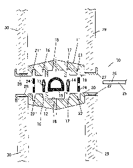
The post assembly comprises a pair of juxtaposed and spaced apart post sections, the facing sides of which are provided internally with a longitudinal groove, the longitudinal grooves ] being arranged in alignment with one another and forming in co-operation, in their respective positions, a recess for receiving a longitudinal support rack member for supporting overhanging removable elements.


French Abstract

La présente invention concerne un ensemble montant qui comprend une paire de sections montant juxtaposées et espacées, dont les côtés se faisant face sont pourvus, à l'intérieur, d'une rainure longitudinale. Les rainures longitudinales sont alignées les unes par rapport aux autres et forment en coopération, dans leur position respective, une dépression destinée à recevoir un porte-éléments longitudinal destiné à soutenir des éléments amovibles suspendus.

Claims

Note: Claims are shown in the official language in which they were submitted.


- 7 -
The embodiments of the invention in which an exclusive property or
privilege is claimed are defined as follows:
1. A post assembly for erecting partitioning walls and receiving product
hangers, said assembly comprising:
a pair of juxtaposed post sections, said juxtaposed post sections having
facing sides with a gap therebetween, said facing sides each having a pair of
parallel longitudinal grooves, said longitudinal grooves of the facing sides
of the
post sections being aligned with one another, each opposed pair of
longitudinal
grooves forming a respective recess; and
a pair of longitudinal support rack members, one of said longitudinal
support rack members being contained in each said recess, each said
longitudinal support rack member having slots therein for receiving removable
hanger elements which may be inserted through the gap between said post
sections into said slots;
each of the post sections having wings defining respective "U" shaped
recesses into which recesses edges of panels or panes can be inserted to form
a
partitioning wall;
the grooves for receiving the longitudinal support rack member being
located behind the recesses defined in the wings, wherein:
each of the post sections has at least one longitudinal channel on
the facing sides thereof, between said longitudinal grooves, and a
connecting element inserted into and bridging said channels, to
interconnect said post sections; and
each said connecting element is configured as a tubular element
having a cross section sufficiently large to keep the facing sides of the
post sections spaced apart.
2. The post assembly according to claim 1, wherein each of said post
sections has an outer surface, opposite the facing sides of the post sections,
said
surface having a continuous profile in cross-section and a convex angular
shape.
3. A partition wall assembly, comprising:

- 8 -
(a) at least one post assembly as defined in claim 1 or 2;
(b) a plurality of wall panels, each seated in one of the U-shaped recess of
an adjacent post assembly; and
(c) a plurality of hangers, each of the hangers having a portion inserted
through said gap between the post sections and engaging at least one of the
slots in the support rack member within said post assembly.

Description

Note: Descriptions are shown in the official language in which they were submitted.


CA 02651365 2010-12-31
- 1 -
POST ASSEMBLY FOR PARTITIONING WALLS
Technical field
The present invention relates to a post assembly for partitioning
walls, particularly of the kind having a support member for supporting
removable overhanging elements, which is adapted to permit said
elements to be easily secured into position, without requiring the use
of screws, bolts .or Other connecting means.
Background art
There are known in the art post assemblies used in the erection
of *partitioning walls inside living spaces or intended spaces fbr
offices, stores or wholesale shops. In some embodiments known in
the art, .the post assemblies are made of a tubular or semi-tubular
section which has, in cross-section, a shape that is appropriate to a
desired aesthetic appearance and exhibits lengthwise a groove which
is adapted to receive a longitudinal support rack member onto which
removable overhanging elements can be secured to form supports for
shelves, suspended factures or the like.
A drawback of these known embodiments is that the longitudinal
support rack member is exposed to view along alm6st Its entire
length, thereby producing a disagreeable contrast with the wall
partitioning elements which are fixed to the post assemblies. Such an
aesthetic discordance is particularly apparent in the case the wall
partitioning elements are made of decorative panels or they consist of
panes of transparent or translucent material.

CA 02651365 2013-09-11
- 2 -
The present invention is aimed at obviating the aforementioned drawback by
providing an improved post assembly for partitioning walls, having a support
member for overhanging removable elements, which member remains practically
hidden to sight, thus giving a higher aesthetic quality to the partitioning
wall.
Disclosure of invention
This object is achieved by the invention in that the post assembly comprises
a pair of juxtapposed and spaced apart post sections, the facing sides of
which
are each provided internally with first longitudinal grooves, the first
longitudinal
grooves of said facing sides of the post sections being arranged in alignment
with one another and forming in co-operation, in their respective positions, a
recess for receiving a longitudinal support rack member for supporting
overhanging removable elements.
In one aspect, the invention provides a post assembly for erecting
partitioning walls and receiving product hangers, said assembly comprising:
a pair of juxtaposed post sections, said juxtaposed post sections having
facing sides with a gap therebetween, said facing sides each having a pair of
parallel longitudinal grooves, said longitudinal grooves of the facing sides
of the
post sections being aligned with one another, each opposed pair of
longitudinal
grooves forming a respective recess; and
a pair of longitudinal support rack members, one of said longitudinal support
rack members being contained in each said recess, each said longitudinal
support rack member having slots therein for receiving removable hanger
elements which may be inserted through the gap between said post sections into
said slots;
each of the post sections having wings defining respective "U" shaped
recesses into which recesses edges of panels or panes can be inserted to form
a
partitioning wall;
the grooves for receiving the longitudinal support rack member being located
behind the recesses defined in the wings, wherein:
each of the post sections has at least one longitudinal channel on the
facing sides thereof, between said longitudinal grooves, and a connecting
element inserted into and bridging said channels, to interconnect said post
sections; and

CA 02651365 2013-09-11
- 2a -
each said connecting element is configured as a tubular element having a
cross section sufficiently large to keep the facing sides of the post sections
spaced apart.
Brief description of drawings
The present invention will now be described in more detail with reference to
the attached drawings, wherein:
Figure 1 is a cross-section view of the post assembly in a disassembled
state,
Figure 2 is a cross-section view of the post assembly in an assembled state,
Figure 3 is a cross-section view of a variant of the post assembly of the
invention in a disassembled state, and
Figure 4 is a cross-section view of the variant of the post assembly of the
invention in an assembled state.

CA 02651365 2010-12-31
- 3 -
Detailed Description of the Exemplary Embodiments
The post assembly generally designated by 10 in
Figures 1 and 2 of the drawings, generally comprises a
pair of juxtaposed post sections 11, 12, which are
connected one another by means of longitudinal connecting elements
13, 14, 15 arranged in suitable longitudinal grooves 16, 17, 18 of the
post sections. Post sections 11, 12 are made of metal material, e.g.
aluminum. Elements 13, 114, 15 are made of rubber or the like.
Connecting elment 15 is configured as a tubular element having, in
cross section, a 'D" shaped configuration and thus is adapted to keep
the facing sides 19, 20 of the post sections 11, 12 apart.
Facing sides 19, 20 of the post sections 11,12 are each provided
internally with a longitudinal groove 21, 22. These longitudinal
grooves 21, 22 are aligned with one another and form in co-
operation, in their respective positions, a recess 23 for receiving a
longitudinal support member 24 onto which overhanging removable
elements 25 can be secured to form supports for shelves, suspended
fixtures or the like.
The sides opposite the facing sides 19, 20 of the post sections
11, 12 exhibit, instead, a continuous profile, i.e. without longitudinal
grooves or recesses, in cross-section, and have a convex angular
shape.
Preferably, the longitudinal support member 24 consists of a rack
member made of metal material, e.g. steel, in order to assure an
excellent strength.

CA 02651365 2008-11-05
WO 2007/138631
PCT/1T2007/000364
- 4 -
The securing of the overhanging elements 25 is obtained in an
easy manner, without = requiring the use of screws, bolts or other
connecting means. To this purpose, a special elongated and slender
portion 26 of the overhanging element 25 is inserted into the space
gap between the facing sides 19, 20 of the post sections 11,12 to
engage with the slots of the rack member.
Conveniently, provision can be made for two pairs of grooves 21,
22 and 211, 221, each pair being adapted to form a recess 23, 231 for
receiving a longitudinal support member 24, 241. By this arrangement,
overhanging removable elements can be secured onto each side of a
partitioning wall supported by the post assembly 10.
The post assembly 10 permits decorative panels or panes of
transparent or translucent material to be assembled on opposite
sides. To this purpose, each post section 11, 12 forming the post
assembly 10 comprises wings 27, 28 which are folded at an angle to
form a "U" shaped recess into which the edges of the panels or panes
29, 30 of the partitioning wall can be inserted.
Referring to Figures 3 and 4 of the drawings, there is shown a
variant of the post assembly according to the invention.
The post assembly of this variant, generally designated by 10,
comprises a pair of juxtapposed post sections 11, 12. The facing
sides 19 and 20 of the post sections 11, 12 are provided with a
groove 31, and a mating ledge 32, respectively. The groove 31 and
the ledge 32 extend lengthwise the post sections for a substantial
length thereof. The height of the ledge 32 is less than the depth of the

CA 02651365 2010-12-31
- 5 -
groove 31, thus in the assembled configuration of the post assembly,
when the post sections '11, 12 mate and the ledge on post section 12
is received into the groove 31 on post section 11, a space gap exists
between the facing sides 19, 20 of the post sections 11, 12.
Also in the variant shown in Figure 3 and 4 of the drawings, the
facing sides 19, 20 are each provided internally with at least a
longitudinal groove 21,_ 22. These longitudinal grooves. 21, 22 are
aligned with one another and form in co-operation, in their respective
positions, a recess 23 for receiving a longitudinal support member 24
onto which overhanging removable elements 25 can , be secured to
form supports for shelves, suspended fixtures or the like. The
securing of the overhanging elements is obtained, also in this variant,
by inserting a special elongated and slender portion 26 of the
overhanging element25 into the space gap between the facing sides
19, 20 of the post section 11, 12 to engage with the slots of the rack
member.
Also in this variant, provision can be made for two pairs of
grooves 21, 22 and 21!, 221, each pair being adapted to form a recess
23, 231 for a longitudinal support member 24, 241. With this
arrangement, the overhanging removable elements can be secured
onto each side of a partitioning wall supported by the post assembly
10.
The post assembly achieves the . aimed object of
hiding from view the longitudinal support rack member 24,
24' for its entire length. The recess 23, 23' for receiving

CA 02651365 2008-11-05
WO 2007/138631- 6 -
PCT/1T2007/000364
the longitudinal support rack member 24, 241 is located adequately
inside the post assembly 10; behind the recess formed by wings 27,
28, thus being practically covered thereby and therefore invisible.
Because the rack member 24, 241 is hidden from view, it does not
require the application of a special finish and this greatly reduces the
cost thereof.
Furthermore, because the rack member 24, 241 is separate from
the sections forming the post assembly 10 it can be adjusted in height
independently from the post sections by suitable adjusting means of
the kind known in the art. This feature is useful, in particular, when
the partitioning wall is erected on a non perfectly levelled floor,
because it permits the overhanging elements 25 to be mounted in any
case at a same level.

Representative Drawing
A single figure which represents the drawing illustrating the invention.
Administrative Status

2024-08-01:As part of the Next Generation Patents (NGP) transition, the Canadian Patents Database (CPD) now contains a more detailed Event History, which replicates the Event Log of our new back-office solution.

Please note that "Inactive:" events refers to events no longer in use in our new back-office solution.

For a clearer understanding of the status of the application/patent presented on this page, the site Disclaimer , as well as the definitions for Patent , Event History , Maintenance Fee  and Payment History  should be consulted.

Event History

Description Date
Time Limit for Reversal Expired 2022-11-25
Letter Sent 2022-05-24
Letter Sent 2021-11-25
Letter Sent 2021-05-25
Common Representative Appointed 2019-10-30
Grant by Issuance 2014-07-15
Inactive: Cover page published 2014-07-14
Pre-grant 2014-04-22
Inactive: Final fee received 2014-04-22
Notice of Allowance is Issued 2013-10-25
Letter Sent 2013-10-25
Notice of Allowance is Issued 2013-10-25
Inactive: Q2 passed 2013-10-22
Inactive: Approved for allowance (AFA) 2013-10-22
Amendment Received - Voluntary Amendment 2013-09-11
Inactive: S.30(2) Rules - Examiner requisition 2013-03-25
Letter Sent 2012-05-14
Request for Examination Requirements Determined Compliant 2012-04-19
All Requirements for Examination Determined Compliant 2012-04-19
Request for Examination Received 2012-04-19
Amendment Received - Voluntary Amendment 2010-12-31
Letter Sent 2010-10-28
Reinstatement Requirements Deemed Compliant for All Abandonment Reasons 2010-10-18
Deemed Abandoned - Failure to Respond to Maintenance Fee Notice 2010-05-25
Inactive: Cover page published 2009-03-03
Inactive: Notice - National entry - No RFE 2009-02-26
Inactive: Office letter 2009-02-26
Letter Sent 2009-02-26
Inactive: First IPC assigned 2009-02-24
Application Received - PCT 2009-02-23
Inactive: Declaration of entitlement - PCT 2008-11-18
National Entry Requirements Determined Compliant 2008-11-05
Application Published (Open to Public Inspection) 2007-12-06

Abandonment History

Abandonment Date Reason Reinstatement Date
2010-05-25

Maintenance Fee

The last payment was received on 2014-04-30

Note : If the full payment has not been received on or before the date indicated, a further fee may be required which may be one of the following

  • the reinstatement fee;
  • the late payment fee; or
  • additional fee to reverse deemed expiry.

Patent fees are adjusted on the 1st of January every year. The amounts above are the current amounts if received by December 31 of the current year.
Please refer to the CIPO Patent Fees web page to see all current fee amounts.

Owners on Record

Note: Records showing the ownership history in alphabetical order.

Current Owners on Record
UNIFOR S.P.A.
Past Owners on Record
PIERO MOLTENI
Past Owners that do not appear in the "Owners on Record" listing will appear in other documentation within the application.
Documents

To view selected files, please enter reCAPTCHA code :


To view images, click a link in the Document Description column. To download the documents, select one or more checkboxes in the first column and then click the "Download Selected in PDF format (Zip Archive)" or the "Download Selected as Single PDF" button.

List of published and non-published patent-specific documents on the CPD .

If you have any difficulty accessing content, you can call the Client Service Centre at 1-866-997-1936 or send them an e-mail at CIPO Client Service Centre.


Document
Description 
Date
(yyyy-mm-dd) 
Number of pages   Size of Image (KB) 
Description 2013-09-10 7 260
Claims 2013-09-10 2 58
Description 2008-11-04 6 238
Claims 2008-11-04 2 82
Drawings 2008-11-04 2 67
Representative drawing 2008-11-04 1 18
Abstract 2008-11-04 2 69
Description 2010-12-30 6 224
Claims 2010-12-30 2 68
Representative drawing 2014-06-16 1 12
Reminder of maintenance fee due 2009-02-25 1 111
Notice of National Entry 2009-02-25 1 193
Courtesy - Certificate of registration (related document(s)) 2009-02-25 1 103
Courtesy - Abandonment Letter (Maintenance Fee) 2010-07-19 1 172
Notice of Reinstatement 2010-10-27 1 163
Reminder - Request for Examination 2012-01-23 1 126
Acknowledgement of Request for Examination 2012-05-13 1 177
Commissioner's Notice - Application Found Allowable 2013-10-24 1 161
Commissioner's Notice - Maintenance Fee for a Patent Not Paid 2021-07-05 1 553
Courtesy - Patent Term Deemed Expired 2021-12-22 1 538
Commissioner's Notice - Maintenance Fee for a Patent Not Paid 2022-07-04 1 543
Correspondence 2008-11-17 2 35
PCT 2008-11-04 2 58
Correspondence 2009-02-25 1 15
Fees 2010-10-17 2 73
Correspondence 2014-04-21 1 31