Language selection

Search

Patent 2651664 Summary

Third-party information liability

Some of the information on this Web page has been provided by external sources. The Government of Canada is not responsible for the accuracy, reliability or currency of the information supplied by external sources. Users wishing to rely upon this information should consult directly with the source of the information. Content provided by external sources is not subject to official languages, privacy and accessibility requirements.

Claims and Abstract availability

Any discrepancies in the text and image of the Claims and Abstract are due to differing posting times. Text of the Claims and Abstract are posted:

  • At the time the application is open to public inspection;
  • At the time of issue of the patent (grant).
(12) Patent: (11) CA 2651664
(54) English Title: BAND CLAMP
(54) French Title: PINCE D'ATTACHE
Status: Granted
Bibliographic Data
(51) International Patent Classification (IPC):
  • F16L 33/025 (2006.01)
(72) Inventors :
  • STREULI, WALTER (Switzerland)
(73) Owners :
  • OETIKER SCHWEIZ AG (Switzerland)
(71) Applicants :
  • HANS OETIKER AG MASCHINEN-UND APPARATEFABRIK (Switzerland)
(74) Agent: KIRBY EADES GALE BAKER
(74) Associate agent:
(45) Issued: 2011-06-14
(86) PCT Filing Date: 2006-05-09
(87) Open to Public Inspection: 2007-11-15
Examination requested: 2008-11-10
Availability of licence: N/A
(25) Language of filing: English

Patent Cooperation Treaty (PCT): Yes
(86) PCT Filing Number: PCT/EP2006/004344
(87) International Publication Number: WO2007/128334
(85) National Entry: 2008-11-10

(30) Application Priority Data: None

Abstracts

English Abstract


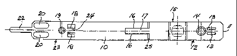
An open hose clamp formed of a band 10 has band end portions 12, 23
which overlap one another in the closed condition of the clamp. For closing
the
clamp, tabs 19 which are folded out of the inner band end portion 23 extend
through two slots 13 provided in the outer band end portion 12, and are folded

upon each other on the outside. An ear-like tightening means 15 serves to
reduce
the circumferential length of the clamp between its closed and tightened
conditions.
The tensile forces then acting between the interconnected band end portions
12, 23 are taken up by two mutually engaging cup-shaped embossments 14,
19 of which the embossment 19 which has a smaller cross-section is formed on
the inner band end portion 23 and engages into a larger embossment 14 provided

on the outer band end portion 12. This force transmitting means has the effect

that no tensile forces are exerted on the slots 13 of the closing means.


French Abstract

Une pince de tuyau flexible ouverte, moulée à partir d'une attache (10) présente des zones terminales (12, 23), qui se chevauchent mutuellement lorsque la pince est à l'état fermé. Pour fermer la pince, deux fentes (13) présentes dans la zone terminale extérieure (12) sont traversées par deux pattes dépliées (18) hors de la zone terminale intérieure (23), lesquelles pattes doivent être repliées l'une vers l'autre sur la face extérieure. Un dispositif de tension de genre auriculaire (15) sert à réduire la longueur périphérique de la pince entre son état fermé et son état tendu. Les forces de traction intervenant entre les zones terminales (12, 23) reliées les unes aux autres sont recueillies par deux cavités (14, 19) en forme d'écuelle pénétrant l'une dans l'autre, dont la cavité la plus petite dans la section transversale est conçue sur la zone terminale intérieure (23) et pénètre dans une cavité plus grande (14) existante dans la zone terminale extérieure (12). Le dispositif de transmission de force ainsi conçu fait que les fentes (13) du dispositif de fermeture n'ont pas besoin de recueillir des forces de traction.

Claims

Note: Claims are shown in the official language in which they were submitted.


-5-

Claims:


1. A clamp formed of a band and having band end portions which overlap in
the closed condition, comprising
closing means including an aperture in one of the band end portions and a
projection on the other band end portion to engage the aperture in the closed
condition of the clamp and hold the mutually overlapping band end portions
upon
one another;
tightening means for tightening the clamp by reducing the circumferential
length thereof between the closed condition and a tightened condition; and
force transmitting means separate from the closing means for positively
transmitting the tensile force which act between the mutually overlapping band

end portions in the tightened condition of the clamp, wherein the force
transmitting
means includes a first cup-shaped embossment formed in one band end portion
and a second cup-shaped embossment formed in the other band end portion to
engage the first cup-shaped embossment in the closed condition of the clamp.


2. The clamp of claim 1, wherein the two cup-shaped embossments are
rounded at least in the area which is adjacent the tightening means in the
inner
embossment and is remote from the tightening means in the outer embossment.

3. The clamp of claim 1 or 2, wherein the two embossments are circular in a
cross-section taken parallel to the band surface.


4. The clamp of any one of claims 1 to 3, wherein the inner dimension of one
embossment is larger than the outer dimension of the other embossment.


5. The clamp of any one of claims 1 to 4, wherein the two embossments are
deep-drawn from the band of the clamp.


-6-

6. The clamp of any one of claims 1 to 5, wherein the closing means includes
a slot formed in one band end portion and extending in the longitudinal
direction of
the band, and a tab bent out of the other band end portion to extend through
the
slot.


7. The clamp of claim 6, wherein the closing means includes two parallel tabs
in that band end portion which is the inner one in the closed condition of the

clamp, the tabs being adapted to extend through corresponding parallel slots
in
the outer band end portion and to be folded upon one another.


8. The clamp of any one of claims 1 to 7, wherein the force transmitting means

is disposed in close proximity to the closing means.


9. The clamp of any one of claims 1 to 8, wherein the force transmitting means

is disposed on the side of the closing means remote from the free end of that
band end portion which is the outer one in the closed condition of the clamp.


10. The clamp of any one of claims 1 to 9, wherein the inner diameter of one
cup-shaped embossment is 3.5 to 4.0 mm and greater by 0.2 to 0.4 mm than the
outer diameter of the other cup-shaped embossment, for a width of the band
from
8 to 15 mm and a band thickness from 0.6 to 1.0 mm.


11. The clamp of any one of claims 1 to 10, wherein the tightening means
includes an ear formed of the band and having two leg portions extending
perpendicular to the band in the non-tightened condition of the clamp, and a
bridge portion connecting the outer ends of the leg portions.

Description

Note: Descriptions are shown in the official language in which they were submitted.


CA 02651664 2010-04-27

- 1 -
BAND CLAMP
Field of the Invention
Embodiments of the present invention relate to the field of band clamps.
Background
US 5,305,499 discloses a clamp formed from a band. The open clamp,
which in the delivery condition is circularly pre-shaped, is placed around the
object
to be clamped with the two band end portions overlapping one another. For
closing the clamp, hooks are provided in the overlapped inner band end portion
which engage apertures provided in the outer band end portion. The clamp is
subsequently tightened by narrowing a so-called "Oetiker ear".
The known clamp has three hooks of which one is formed as a guide hook
in the form of a tab bent from the band material to extend through a slot
provided
in the outer band end portion and extending in the longitudinal direction of
the
band. The further two hooks are support hooks stamped out of the inner band
end
portion by cold deformation to engage corresponding edges of window-shaped
apertures in the outer band end portion. The edge of the guide hook remote
from
the inner band end extends obliquely outward so that, when the clamp is
tightened, the mutually overlapping band end portions are guided toward each
other and are maintained in close overlapping.
The tensile forces which occur between the two band end portions in the
tightened condition of the clamp are transmitted primarily from the two
support
hooks formed at the inner band end portion onto the edges of the window-shaped
apertures formed in the outer band end portion remote from the tightening
means.
It has been found that when the tensile forces to be transmitted are
increased,
material failure will occur at these aperture or window edges.
US 5,138,747 discloses a hose clamp which has an elasticity reserve in the
form of an attached spring and an additional means for limiting the force
acting on
the spring. This limiting means also uses a hook that engages the edge of an
aperture at the given maximum force.


CA 02651664 2010-04-27

-2-
Summary of the Invention
Embodiments are based on the object of providing a clamp which is formed
from a band, i.e. an open clamp, that withstands higher tensile forces than
comparable prior art clamps of the same material and dimension.
Certain exemplary embodiments can provide a clamp formed of a band and
having band end portions which overlap in the closed condition, comprising
closing means including an aperture in one of the band end portions and a
projection on the other band end portion to engage the aperture in the closed
condition of the clamp and hold the mutually overlapping band end portions
upon
one another; tightening means for tightening the clamp by reducing the
circumferential length thereof between the closed condition and a tightened
condition; and force transmitting means separate from the closing means for
positively transmitting the tensile force which act between the mutually
overlapping band end portions in the tightened condition of the clamp, wherein
the
force transmitting means includes a first cup-shaped embossment formed in one
band end portion and a second cup-shaped embossment formed in the other
band end portion to engage the first cup-shaped embossment in the closed
condition of the clamp.
In accordance with further embodiments, force transmitting means is
provided in addition to, and separate from, the closing means for positively
transmitting the tensile force which acts between the mutually overlapping
band
end portions in the tightened condition of the clamp. The closing means, which
includes an aperture in one of the band end portions and a projection on the
other
band end portion for engaging the aperture, is thus relieved of tensile forces
to be
transmitted. Different from the prior art, the (at least one) aperture, which
is part of
the closing means and which necessarily weakens the band material, is not also
used for transmitting forces. Tests have shown that the clamp of the invention
breaks within the area of the full band width, possibly in the area of the
tightening
means, but not at the closing means and is thus capable to withstand higher
forces.
The configuration of the force transmitting means can be particularly
advantageous because cup-shaped embossments in the band material increase
the stability of the material rather than decreasing it.


CA 02651664 2010-04-27

- 2a -

The at least partially rounded shape of the embossments can avoid stress
peaks in the force transmitting area.
In other embodiments, the embossments engage one another with play
which facilitates the closing of the clamp without impairing the force
transmission.
Other embodiments provide an advantage in so far as the mutually
overlapping band end portions are closely held upon one another in the closed
condition of the clamp. In combination with the other features, this has the
effect
that the two mutually engaging embossments cannot become disengaged even
under high tensile forces.

Brief Description of the Drawings
Embodiments of the invention will be described below with reference to the
drawings. In the drawings:
Fig. 1 is a side view of a hose clamp in the closed but not tightened
condition;
Fig. 2 is a side view of the hose clamp band in the straight but otherwise
completely formed condition of the clamp;
Fig. 3 is a plan view of the clamping band shown in Fig. 2;
Fig. 4 is a cross-sectional view taken at the location A-A of Fig. 1; and


CA 02651664 2008-11-10

-3-
Figs. 5 and 6 are enlarged cross-sectional views of the embossments provided
in
the clamping band at the locations marked Y and Z in Fig. 2.

Detailed description of embodiments
The hose clamp shown in the drawing is made from a steel band 10 having a
width of 8 to 15 mm, typically 10 mm, and a band thickness of 0.6 to 1.0 mm,
typi-
cally 0.8 mm. Starting from the free end 11 of the band end portion 12, which
constitutes the outer band portion in the closed condition of the clamp shown
in
Fig. 1, the following structures are formed in the band 10: -
two parallel slots 13 extending in the longitudinal direction of the band;
a cup-shaped embossment 14;
an ear-shaped tightening means 15;
a central band portion 17 laterally cut free by two longitudinal cuts 16 and
pressed out of the band 10;
two tabs 18 cut free on three sides, bent out of the band 10, and extending
parallel to the longitudinal direction of the band;
a further cup-shaped embossment 19;
two guide portions bent out of the band 10 and extending parallel to the
longitudinal direction of the band; and
a tongue 22 extending from the opposite end 21 of the band 10.

In the closed condition of the clamp shown in Fig. 1, the slots 13 and the
first
cup-shaped embossment 14 are formed in the outer band end portion 12,
whereas the tabs 18 and the second cup-shaped embossment 19 are formed in
the inner band end portion 23.
The two cup-shaped embossments 14 and 19, which are formed by deep-
drawing the material of the band 10, are essentially inverted-U-shaped in the
longitudinal section of the band and circular in the plan view. The inner
diameter
of the embossment 14 provided in the outer band portion 12 is 3.5 to 4.0 mm,
typically 3.8 mm, and is larger by 0.2 to 0.4 mm, typically 0,3 mm than the
outer
diameter of the embossment 19 formed in the inner band end portion 23. Thus,
the two embossments 14 and 19 engage one another with play and are therefore
easily brought into engagement when the clamp is closed.
In the closed condition of the clamp, the tabs 18 extend through the slots 13
and are folded upon one another on the outer side of the outer band end
portion
12, as shown in Fig. 6, so that they substantially completely surround a web
24 of
the band 10 that remains between the tabs 18. Since the slots 13 are formed
near
the free end 11 of the outer band end portion 12, the latter is held tightly
on the


CA 02651664 2008-11-10

-4-
inner band end portion 23 which, in turn, surrounds the object to be clamped
(not
shown). As a result, the two cup-shaped embossments 14 and 19 are securely
held in mutual engagement.
In the closed condition of the clamp shown in Fig. 1, the free end of the
tongue 22 extends into the area of a step 25 formed in the band end 10 where a
slot starts that is formed by the two cuts 16 underneath the pressed-out
central
band portion 17.
The ear 15, which forms the tightening means, has two leg portions 26
which, in the non-tightened condition of the clamp, extend perpendicularly to
the
band 10, and a bridge portion 26 which connects the outer ends of the leg por-
tions 26 and is reinforced by a depressed bead 28 which is guided between the
guide regions 20.
For tightening the clamp, the ear 15 is squeezed by a pliers-type tool applied
to the feet of the leg portions 26 to reduce the circumferential length of the
clamp,
whereby the tongue is further moved underneath the pressed-out central band
portion 17. The tensile forces which then occur between the outer band end por-

tion 12 and the inner band end portion 23, act on the mutually engaging cup-
shaped embossments 14 and 19 which contact one another in the region of the
outer embossment 14 remote from the ear 15. The closed round shape of the
embossments 14 and 19 allows very high forces to be transmitted. On the other
hand, the slots 13 through which the tabs 18 of the closing means are guided
are
left free of tensile forces.
To hold the embossments 14 and 19 in secure engagement, it is useful to
arrange them as closely as possible to the closing means formed by the slots
13
and tabs 18. This arrangement will also avoid an unnecessary length of the
band.
Since the slots 13 are not exposed to tensile forces, they may terminate
close to the free end 11 of the outer band end portion. This also permits a
saving
in band length.
The embossments 14 and 19 do not have to have the circular shape shown
in the above embodiment. To avoid peak stress peaks, it is useful for them to
be
rounded at least in that area which in the outer embossment 14 is remote from
the
ear 15. In other words, the embossments 14 and 19 should contact one another
in
their right-hand areas as shown in Figs. 4 and 5.
The materials and dimensions given above are mentioned only for illustrating
a typical embodiment. The invention is generally applicable to band clamps
made
of other materials and in other dimensions.

Representative Drawing
A single figure which represents the drawing illustrating the invention.
Administrative Status

For a clearer understanding of the status of the application/patent presented on this page, the site Disclaimer , as well as the definitions for Patent , Administrative Status , Maintenance Fee  and Payment History  should be consulted.

Administrative Status

Title Date
Forecasted Issue Date 2011-06-14
(86) PCT Filing Date 2006-05-09
(87) PCT Publication Date 2007-11-15
(85) National Entry 2008-11-10
Examination Requested 2008-11-10
(45) Issued 2011-06-14

Abandonment History

There is no abandonment history.

Maintenance Fee

Last Payment of $624.00 was received on 2024-04-30


 Upcoming maintenance fee amounts

Description Date Amount
Next Payment if standard fee 2025-05-09 $624.00
Next Payment if small entity fee 2025-05-09 $253.00

Note : If the full payment has not been received on or before the date indicated, a further fee may be required which may be one of the following

  • the reinstatement fee;
  • the late payment fee; or
  • additional fee to reverse deemed expiry.

Patent fees are adjusted on the 1st of January every year. The amounts above are the current amounts if received by December 31 of the current year.
Please refer to the CIPO Patent Fees web page to see all current fee amounts.

Payment History

Fee Type Anniversary Year Due Date Amount Paid Paid Date
Request for Examination $800.00 2008-11-10
Application Fee $400.00 2008-11-10
Maintenance Fee - Application - New Act 2 2008-05-09 $100.00 2008-11-10
Maintenance Fee - Application - New Act 3 2009-05-11 $100.00 2009-04-14
Maintenance Fee - Application - New Act 4 2010-05-10 $100.00 2010-03-19
Final Fee $300.00 2011-03-14
Maintenance Fee - Application - New Act 5 2011-05-09 $200.00 2011-03-25
Maintenance Fee - Patent - New Act 6 2012-05-09 $200.00 2012-03-30
Maintenance Fee - Patent - New Act 7 2013-05-09 $200.00 2013-04-10
Maintenance Fee - Patent - New Act 8 2014-05-09 $200.00 2014-04-30
Maintenance Fee - Patent - New Act 9 2015-05-11 $200.00 2015-05-05
Registration of a document - section 124 $100.00 2015-06-18
Maintenance Fee - Patent - New Act 10 2016-05-09 $250.00 2016-05-02
Maintenance Fee - Patent - New Act 11 2017-05-09 $250.00 2017-04-27
Maintenance Fee - Patent - New Act 12 2018-05-09 $250.00 2018-04-13
Maintenance Fee - Patent - New Act 13 2019-05-09 $250.00 2019-04-30
Maintenance Fee - Patent - New Act 14 2020-05-11 $250.00 2020-04-29
Maintenance Fee - Patent - New Act 15 2021-05-10 $459.00 2021-04-28
Maintenance Fee - Patent - New Act 16 2022-05-09 $458.08 2022-04-26
Maintenance Fee - Patent - New Act 17 2023-05-09 $473.65 2023-04-24
Maintenance Fee - Patent - New Act 18 2024-05-09 $624.00 2024-04-30
Owners on Record

Note: Records showing the ownership history in alphabetical order.

Current Owners on Record
OETIKER SCHWEIZ AG
Past Owners on Record
HANS OETIKER AG MASCHINEN-UND APPARATEFABRIK
STREULI, WALTER
Past Owners that do not appear in the "Owners on Record" listing will appear in other documentation within the application.
Documents

To view selected files, please enter reCAPTCHA code :


To view images, click a link in the Document Description column. To download the documents, select one or more checkboxes in the first column and then click the "Download Selected in PDF format (Zip Archive)" or the "Download Selected as Single PDF" button.

List of published and non-published patent-specific documents on the CPD .

If you have any difficulty accessing content, you can call the Client Service Centre at 1-866-997-1936 or send them an e-mail at CIPO Client Service Centre.


Document
Description 
Date
(yyyy-mm-dd) 
Number of pages   Size of Image (KB) 
Abstract 2008-11-10 1 24
Claims 2008-11-10 2 86
Drawings 2008-11-10 1 23
Description 2008-11-10 4 233
Representative Drawing 2008-11-10 1 5
Cover Page 2009-03-13 1 39
Description 2010-04-27 5 247
Claims 2010-04-27 2 74
Abstract 2011-05-19 1 24
Representative Drawing 2011-05-30 1 6
Cover Page 2011-05-30 1 41
PCT 2008-11-10 12 382
Assignment 2008-11-10 4 93
Correspondence 2009-05-27 5 175
Correspondence 2009-11-26 4 168
Prosecution-Amendment 2010-02-15 2 47
Correspondence 2010-02-23 4 170
Prosecution-Amendment 2010-04-27 8 333
Correspondence 2011-03-14 1 36
Assignment 2015-06-18 7 305