Note: Descriptions are shown in the official language in which they were submitted.
CA 02651768 2008-11-07
WO 2007/128805 PCT/EP2007/054388
DESCRIPTION
<<APPARATUS FOR MEASURING AND CHECKING MECHANICAL PIECES>>
Technical Field
The present invention relates to an apparatus for measuring
and checking a mechanical piece including a support and
protection structure that defines a longitudinal axis of
the apparatus and includes a first connector; a probe
connected to the support and protection structure, that
includes at least one armset with at least one feeler
adapted for contacting the mechanical piece to be checked;
at least one transducer adapted for generating electrical
signals representative of displacements of said at least
one feeler; and a second connector adapted for cooperating
with the first connector.
The present invention also relates to an apparatus for
measuring and checking a mechanical piece including a
support and protection structure that defines a
longitudinal axis of the apparatus and includes a first
connector; a probe that includes at least one armset with
at least one feeler adapted for contacting the mechanical
piece to be checked and a mechanical transmission system;
at least one transducer adapted for generating electrical
signals representative of displacements of said at least
one feeler; a second connector connected to said at least
one transducer and adapted for coupling the first
connector; and a wireless transmission system of the
electrical signals, including at least one battery and an
emitting device.
There are known checking apparatus, for examples gauges of
the so-called "plug" type, for the dimensional and shape
checking of mechanical pieces.
Patent US-A-4348814 discloses examples of such gauges,
wherein a measuring armset connected to the support
includes two feelers fixed to movable arms in diametrical
CA 02651768 2008-11-07
WO 2007/128805 PCT/EP2007/054388
-2-
opposite positions, for contacting the surface of a hole to
be checked. A transducer detects mutual displacements
between the movable arms and provides for electrical
signals indicative of the mutual position of the feelers,
through the wires of a cable, to external display and
processing devices.
There are also known wireless plug gauges, wherein signals
representative of the dimension to be checked and generated
by the transducer are wirelessly transmitted to external
display and processing units.
The known plug gauges can be manually operated and
typically include a support and protection structure with a
handle with an external surface that acts as handgrip for
being used by an operator and a probe containing mechanical
devices for detecting the dimensions of the hole. The probe
may be separated from the main body for being replaced
depending on the checking to be performed, for example
depending on the nominal diameter of the hole to be
checked.
Patent US-A-4571839 discloses an example of such manual
plug gauges with detachable and replaceable probe. The
illustrated plug gauge is of the electrical type with cable
measurement transmission and power supply, with a hollow,
tubular support and protection structure that acts as
handle whereto a probe is connected. The probe, that
contains a measuring cell with associated transducer and
feelers, is connected to the hollow tubular structure by
means of a mechanical coupling with a first screw that
crosses a through hole achieved in the tubular structure
and engages on a circular groove achieved on the probe. The
measuring cell is locked with respect to the probe in
analogous way, by means of a second screw that crosses a
through hole achieved in an external circular portion of
the probe and engages on a groove achieved on a support for
the transducer.
The handle includes at its interior electrical cables of
the transducer that are connected to external power supply
CA 02651768 2008-11-07
WO 2007/128805 PCT/EP2007/054388
-3-
electrical cables by means of corresponding connectors.
The plug gauge hereinbefore described guarantees a certain
flexibility in use by virtue of the possibility of
replacing the probe depending on the required checking,
although such replacing operation is not particularly easy
and convenient because of the utilized coupling system and
the arrangement of the electrical connectors which result
to be of difficult access. Moreover, the coupling between
probe and handle is not particularly precise and guarantees
just limited metrological performances. In fact, screw and
associated groove do not prevent possible mutual rotations
between probe and handle, or between transducer and probe,
with a further disadvantage that the electrical wires may
twist and provoke undesired stress on the transducer.
Object of the present invention is that to improve
modularity and convenience in use of the known gauges,
cutting down costs and enhancing metrological performances
of the gauges.
This and other objects are achieved by a measuring
apparatus with a connection system between probe and
support and protection structure that simplifies and makes
the connection more precise.
An apparatus for measuring and checking mechanical pieces
according to a first embodiment of the present invention
includes a support and protection structure that defines a
longitudinal axis of the apparatus and includes a first
connector; a probe connected to the support and protection
structure, that includes at least one armset with at least
one feeler adapted for contacting the mechanical piece to
be checked; at least one transducer adapted for generating
electrical signals representative of displacements of said
at least one feeler; and a second connector adapted for
cooperating with the first connector. The apparatus
according to the invention is characterized by including an
interface element, connected in a removable way to at least
one of said support and protection structure and probe and
adapted to refer and connect in a rapid way the probe to
CA 02651768 2008-11-07
WO 2007/128805 PCT/EP2007/054388
-4-
the support and protection structure.
The checking apparatus of the present invention includes a
connection system between the support and protection
structure and the probe with an interface element including
first mechanical references to prevent rotation of the
probe about the longitudinal axis with respect to the
interface element and second mechanical references to
prevent rotation of the support and protection structure
about the longitudinal axis with respect to the interface
element. Seats Corresponding to the mechanical references
of the interface element are present on components of the
probe and of the support and protection structure.
An apparatus for measuring and checking mechanical pieces
according to a second embodiment of the present invention
includes a support and protection structure that defines a
longitudinal axis of the apparatus and includes a first
connector; a probe that includes at least one armset with
at least one feeler adapted for contacting the mechanical
piece to be checked and a mechanical transmission system;
at least one transducer adapted for generating electrical
signals representative of displacements of said at least
one feeler; a second connector connected to said at least
one transducer and adapted for coupling the first
connector; and a wireless transmission system of said
electrical signals, including at least one battery and an
emitting device. The apparatus according to the second
embodiment of the invention is characterized in that said
apparatus further includes a connection system between the
support and protection structure and the probe, connected
in a removable way to at least one of said support and
protection structure and probe.
The connection system between the support and protection
structure and the probe of the checking apparatuses
according to the present invention guarantees quick
interchangeability of different types of probes on the same
handle or on different handles for different types of
checking, and assures electrical stability and reliability
CA 02651768 2008-11-07
WO 2007/128805 PCT/EP2007/054388
-5-
of the connection, protection of the connectors from
mechanical stresses deriving from the normal use of the
gauge in more or less aggressive environments, liquid
tightness so that to protect the internal, sensitive parts
of the probe and handle.
The combination of the above mentioned connection system
and of a wireless transmission system, in the preferred
embodiments of the invention, guarantees particular
flexibility in use and management of the components, that
can be assembled and utilized in an extremely simple and
rapid way.
The invention will be described in detail with reference to
the enclosed sheets of drawings, given by way of non
limiting examples only, wherein:
figure 1 shows a perspective view of a plug gauge
according to a first preferred embodiment of the invention
with some details omitted for the sake of simplicity;
figure 2 shows a perspective view of the handle of the
plug gauge of figure 1, according to a different angular
position and on a different scale with respect to figure 1;
figure 3 shows a perspective view of a component of
the plug gauge nosepiece of figure 1, according to a
different angular position and on a different scale with
respect to figure 1;
figure 4 shows a perspective view of a first connector
of the plug gauge of figure 1, according to a different
angular position and on a different scale with respect to
figure 1;
figure 5 shows a perspective view of a second
connector of the plug gauge of figure 1, according to a
different angular position and on a different scale with
respect to figure 1;
figure 6 shows a perspective view of the assembled
connectors of figure 4 and 5, according to a different
angular position and on a different scale with respect to
figures 4 and 5;
figure 7 shows an exploded view of a connection system
CA 02651768 2008-11-07
WO 2007/128805 PCT/EP2007/054388
-6-
between handle and probe of the plug gauge of figure 1,
according to a different angular position and on a
different scale with respect to figure 1;
figure 8 shows a perspective view of a plug gauge
according to a second preferred embodiment of the invention
with some details omitted for the sake of simplicity;
figure 9 shows a longitudinal cross-sectional
perspective view of a connection system between handle and
probe of the plug gauge of figure 8, according to a
different angular position and on a different scale with
respect to figure 8;
figure 10 shows an exploded view of some component
parts of the plug gauge of figure 8, according to a
different angular position and on a different scale with
respect to figure 8;
figure 11 shows an exploded view of a connection
system between handle and probe of the plug gauge of figure
8, according to a different angular position and on a
different scale with respect to figure 8;
figure 12 shows a perspective view of a plug gauge
according to a third preferred embodiment of the invention;
figure 13 shows a perspective view of a connection
system and probe of the plug gauge of figure 12;
figure 14 shows a perspective view of the connection
system of the figure 13 according to a different angular
position and on a different scale with respect to figure
13; and
figure 15 shows a longitudinal cross-sectional
perspective view of the connection system and probe of the
plug gauge of figure 12, according to a different angular
position and on a different scale with respect to figure
12.
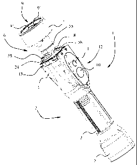
Figure 1 shows an electrical gauge of the plug type 1 for
the manual checking of internal diametral dimensions with
wireless transmission of measurement signals. The plug
gauge 1 includes a support and protection structure with a
handle 2 that defines a longitudinal axis of the plug gauge
CA 02651768 2008-11-07
WO 2007/128805 PCT/EP2007/054388
-7-
1 and is shaped in such a way that has a central portion 3
with reduced diameter with respect to a first 4 and a
second 5 end portion. The central portion 3 has ergonomic
shape for the manual use of the gauge. In particular,
figure 2 shows the support and protection structure with
the handle 2, the front part of which - at the first end
portion 4 - is protected by a closure element or cap 13
with a central opening 71 that makes a first connector
(handle-side) 16 accessible. The handle 2 contains a push-
button group 12, including a push-button 10 for controlling
the plug gauge 1, i.e. for manually selecting by an
operator the plug gauge function required, as for example
the turning on and turning off of the plug gauge, or the
transmission of signals representative of the checked
dimension to an external processing and display device not
shown in the figures. Next to the push-button 10 there is
positioned a display LED 11 that shows the status of the
plug gauge and/or the selected function by means of the
push-button 10.
A probe 6 is connected to the cap 13 of the handle 2 by
means of an interface element 8. The connection between the
probe 6 and the handle 2 will be hereinafter illustrated in
more detail with reference to the figures 2-7.
The probe 6 includes a main element 24 (illustrated in
detail in figure 3), a centering nosepiece 7, locked with
respect to the main element 24 by means of a ring nut 55,
that houses a measuring armset 9 of a known type (only
partially visible in figure 1) with an inductive transducer
and feelers (not illustrated) connected to movable arms 9'
of the measuring armset to contact the piece to be checked.
The transducer, by detecting mutual movements of the arms
9', provides in a known way measurement electrical signals
representative of the dimension to be checked.
The nosepiece 7 can be closed by a protection cap, not
illustrated for the sake of clarity. The main element 24 is
substantially cylindrically shaped with transversal cross-
sections of different external diameter and is hollow for
CA 02651768 2008-11-07
WO 2007/128805 PCT/EP2007/054388
-8-
allowing electrical conductors of the transducer of the
measuring armset 9 to pass. The measuring armeset 9 is
fixed, for example welded, to a bearing holed disk 45 of
the main element 24. The main element 24 has an internal
cylindrical surface 66 and a quadrangular surface 51,
radiused with the former, including two seats 48, 49 for
corresponding keys 37, 38 of a second connector (probe-
side) 17 that will be hereinafter illustrated in detail.
The difference in shape and dimension of the internal
cylindrical surface 66 with respect to the quadrangular
surface 51 creates an internal transversal abutment surface
47. The main element 24 further features an end portion 50,
opposite to the bearing holed disk 45, with an internal
surface 46 and an external surface 46', both threaded.
Between the bearing disk 45 and the end portion 50, in an
intermediate position, there is a central portion 60 with
an abutment surface 62 and seats 61 for the interface
element 8 and associated first mechanical references, more
specifically antirotation keys 63, respectively, that will
be illustrated in detail with reference to the figure 7.
The handle 2 contains, just partially visible in figure 2,
a support element 20 for electronic devices, not visible in
the figure, including circuits for processing the
measurement electrical signals provided for by the
transducer, circuits for managing the push-button group,
circuits for wirelessly transmitting the processed signals
to remote devices by means of an emitting device, and
moreover circuits for managing the power supply, provided
for by batteries (not visible) housed in the central part
of the handle 2. The support element 2 is fixed, and the
above mentioned circuits with it, by means of screws 57 to
the cap 13 which is in turn fixed to the handle 2 by means
of screws 19. In substance, therefore, the handle 2
contains all the necessary circuits necessary to operate
the plug gauge 1, while the probe 6 contains the
measurement armset with associated transducer, the feelers
and the centering nosepiece.
CA 02651768 2008-11-07
WO 2007/128805 PCT/EP2007/054388
-9-
The support element 20 features a central hole 22 with an
abutment surface (not visible) and a seat 15 suitably
shaped to allow the handle-side connector 16 (illustrated
in detail in figure 4) to be inserted and positioned. The
handle-side connector 16 is substantially cylindrically
shaped, with a central part 27 with larger diameter with
respect to a first 26 and a second 32 end portion to
contact the abutment surface of the hole 22. On the central
part 27 there is achieved a plane portion or mechanical
reference key 28 corresponding to the seat 15 of the hole
22, that achieves a first antirotation system between the
handle-side connector 16 and the handle 2, that counteracts
and eliminates possible rotational thrusts on the handle-
side connector 16 about the longitudinal axis and assures
the proper assembly and positioning of the handle-side
connector 16 with respect to the support 20 and thus to the
handle 2. Between the central part 27 and the first end
portion 26 there is achieved a groove 34 for positioning a
gasket 35, for example of the 0-ring type, for assuring
tightness between the handle-side connector 16 and the
support element 20, once they are coupled. The handle-side
connector 16 includes at the first end portion 26 a
plurality of terminals 29 for connecting to the electronic
circuits contained in the handle 2 (or to electrical, power
supply and transmission cables, through a printed circuit,
in case of gauges with cable), and at the second end
portion 32 suitably seats 30 for connecting to
corresponding terminals 31 of the probe-side connector 17.
At an external surface 33 of the second end portion 32
there are achieved first mechanical references or
mechanical reference keys 14 for coupling to the probe-side
connector 17.
In figure 5 there is illustrated in detail the probe-side
connector 17. Likewise the handle-side connector 16, the
probe-side connector 17 is also substantially cylindrically
shaped with a central part 36 with larger diameter with
respect to a first end portion 25 and a second end portion
CA 02651768 2008-11-07
WO 2007/128805 PCT/EP2007/054388
-10-
39. The first end portion 25 is cylindrically shaped with a
groove 41 for a gasket (not illustrated) that assures
tightness between the probe-side connector 17 and the main
element 24 and is closed by a disk 42 whereon there are
fixed terminals 40 for the connection to the transducer.
The second end portion 39 is hollow cylindrically shaped
with an external threaded surface and an internal surface
43 that defines seats 44 corresponding to the mechanical
reference keys 14 of the handle-side connector 16. The
arrangement and shape of the keys 14 and of the
corresponding seats 44 is such that there exist just one
mutual angular position between the connectors 16 and 17
that allow the mutual insertion thereof, so guaranteeing
their proper mutual mechanical arrangement.
As previously mentioned, the central part 36 of the probe-
side connector 17 features two plane portions or reference
keys 37 and 38, and, as the probe-side connector 17 is
mounted within the main element 24, such central part 36
lies at the transversal abutment surface 47 of the main
element 24, and the reference keys 37, 38 couple with the
associated seats 48, 49 of the quadrangular surface 51 so
achieving a second antirotation system for the probe-side
connector 17 that prevents both the transducer electrical
cables and handle electrical cables (in case of handle with
cable transmission) to roll up. The probe-side connector 17
is kept in abutment on the internal transversal abutment
surface 47 by means of a ring nut not illustrated screwed
to the internal threaded surface 46 of the main element 24.
In figure 6 there are illustrated the connectors 16 and 17
inserted one into the other. It should be noticed that the
second end portion 39 of the probe-side connector 17 does
not abut on the central part 27 of the handle-side
connector 16, indeed the mutual insertion of the two
connectors 16, 17 is also defined by the longitudinal
position of the interface element 8 with respect to the
main element 24. It should be further noticed that the
mutual insertion of the connectors 16, 17, together with
CA 02651768 2008-11-07
WO 2007/128805 PCT/EP2007/054388
-11-
the proper arrangement and consequent action of the gaskets
that are present, guarantees the connection to be
waterproof.
In figure 7 there are also illustrated the probe 6, the
interface element 8 and the cap 13 of the handle 2. The
interface element 8 is substantially disk-shaped with an
upper surface 68 and a lower surface 69, a central through
hole 64 for housing the probe 6, more specifically the main
element 24, and three peripheral through holes arranged
substantially at 120 one from the other for three screws
58. At the rim of the central hole 64, on the upper surface
68, there are positioned first mechanical references
including the antirotation keys 63. The interface element 8
is locked in abutment position against the central portion
60 of the main element 24 by a ring nut 53 and a lock nut
54 screwed onto the threaded external surface 66 of the
main element 24. In fact, as the central hole 64 has
diameter smaller than the diameter of the central portion
60 of the main element 24, the upper surface 68 of the
interface element 8 abuts on the central portion 60 and the
antirotation keys 63 couple with the associated seats 61.
As the arrangement of the antirotation keys 63 and of the
associated seats 61 - arranged at 90 one from the other -
leaves four possibilities of coupling between the probe 6
and the interface element 8, it is foreseen the possibility
to indicate an assembly reference on the interface element
8 and on the main element 24, for example by means of
punching, in order to assure a specific arrangement.
Alternatively, it is also possible to utilise a different
number of antirotation keys 63 and of associated seats 61
and/or different spatial arrangement, so to leave just one
possibility of coupling.
After the interface element 8 has been locked with respect
to the probe 6 by means of the ring nut 53 and the lock nut
54, the probe 6 is fixed to the handle 2 by means of the
interface element 8. The latter further includes second
mechanical references on the lower surface 69 including two
CA 02651768 2008-11-07
WO 2007/128805 PCT/EP2007/054388
-12-
pins (of reduced dimensions and thus not visible in the
figure 7) fixed in positions 72 and 73 diametrically
opposite for associated seats 70 of the cap 13 of the
handle 2 and is locked to the handle 2 by means of the
screws 58 screwed in corresponding threaded holes 65 of the
cap 13.
The interface element 8, by coupling with the main element
24 and with the cap 13, achieves a main antirotation system
about the longitudinal axis between the probe 6 and the
support and protection structure (more specifically between
the probe 6 and the handle 2) and it assures the correct
assembly between them. More specifically, the antirotation
keys 63 with the associated seats 61 of the central portion
60 of the main element 24 assure antirotation between the
probe 6 and the interface element 8, while the pins of the
interface element 8, along with the screws 58, assure
correct positioning and antirotation between the interface
element 8 and the cap 13 of the handle 2. Possible
rotational thrusts about the longitudinal axis on the probe
6 are discharged on the handle 2 through, in sequence, the
interface element 8 and the cap 13. In substance, the main
antirotation system prevents mutual rotations of the
connectors 16 and 17 about the longitudinal axis.
It is clear that the spatial arrangement of the pins of the
interface element 8, and the screws 58 as well, is
consistent with the arrangement of the keys 14 of the
handle-side connector 16 and the associated seats 44 of the
probe-side connector 17, so achieving just one possible
connection between the probe 6 and the handle 2.
Thanks to the connection system between the probe 6 and the
handle 2 that has been illustrated, assembly and/or
replacement operations of a probe on the associated handle
results particularly precise and quick. In fact, as
previously seen, the couplings between the connectors 16
and 17, and between the interface element 8 and the cap 13
as well, are univocal and do not allow a wrong connection.
In practice, the operator during the assembly operations is
CA 02651768 2008-11-07
WO 2007/128805 PCT/EP2007/054388
-13-
"forced" to connect the probe 6 and the handle 2 in a
correct way. Moreover, such assembly operations can be
easily carried out, because the probe 6 and the handle 2
are simply coupled by pressure and are locked by screwing
the three screws 58 that connect the interface element 8 to
the cap 13 of the handle 2. The disassembly can be carried
out in an as much easy way, by simply unscrewing the screws
58 and then unthreading the probe 6 together with the
interface element 8. Then, if it were required to separate
the probe 6 from the interface element 8, it would be
sufficient to unscrew the ring nut 53 and the lock nut 54
in order to unthread the interface element 8 from the main
element 24, so that the interface element 8 can be utilized
again on a different probe.
In figures 8-11 there is illustrated a mechanical plug
gauge 111 according to a second embodiment of the invention
wherein a mechanical probe 80 with at least one armset and
transmission elements is utilized. The plug gauge 111
further includes a support and protection structure with a
handle 2, substantially identical to that illustrated with
reference to the figures 1-7 and therefore referenced to by
the same numbers, that defines a longitudinal axis of the
plug gauge 111, and a connection system 110 that will be
hereinafter described in detail. The handle 2 comprises a
push-button group 12 for controlling the plug gauge 111 and
a cap 13 with a central opening 71 that makes a first,
handle-side connector 16 accessible.
The mechanical probe 80 comprises a centering nosepiece 81
with two openings 86 (only one is visible in the figures 8
and 10) for feelers (not illustrated) to pass and a
connection member 82, protruding from the nosepiece 81 and
locked with respect to it by means of a ring nut 83. The
centering nosepiece 81 houses measuring means of a known
type (not visible in the figures), coupled and referred to
the connection member 82. For example, the centering
nosepiece 81 advantageously houses two armsets of the
parallelogram type, with a pair of parallel laminae with
CA 02651768 2008-11-07
WO 2007/128805 PCT/EP2007/054388
-14-
two reduced cross-section or fulcra, whereto the feelers
are coupled. The armsets comprise inclined surfaces, e.g.
forming a Vee-shaped seat, whereon a ball of a mechanical
transmission system comprising a transmission rod 88 is
engaged. In practice, a mutual displacement of the feelers
along a measuring direction transversal to the longitudinal
axis is transduced in a known way into a displacement of
the transmission rod 88 along the longitudinal axis. A
mechanical transmission system of this kind is partially
shown in figure 15.
The connection member 82 is hollow for the rod 88 to pass
and is externally threaded in a part protruding from the
centering nosepiece 81 in order to be screwed on a
corresponding first internal threaded portion 106 of an
adjusting and coupling element 89.
The adjusting and coupling element 89 has a second internal
threaded portion 107 adapted for being screwed on a
corresponding external threaded portion 104 of an interface
element 90.
In practice, the mechanical probe 80 is screwed on the
adjusting and coupling element 89 until the ring nut 83
abuts on the adjusting and coupling element 89, which is in
turn screwed on the interface element 90. The adjusting and
coupling element 89 is locked in position by means of a
ring nut 108 and a lock nut 109, that determine a
longitudinal position of the adjusting and coupling element
89 and, consequently, of the mechanical probe 80 with
respect to the interface element 90. The adjusting and
coupling element 89, the interface element 90, the ring nut
108 and the return ring nut 109 define the connection
system 110 of the mechanical plug gauge 111 illustrated in
figures 8-11 between the mechanical probe 80 and the handle
2. It should be noticed that the threaded coupling between
the interface element 90 and the adjusting and coupling
element 89 achieves a very precise coupling which provides
for the possibility of fine adjustment of the longitudinal
position of the mechanical probe 80 with respect to the
CA 02651768 2008-11-07
WO 2007/128805 PCT/EP2007/054388
-15-
interface element 90, which, as will be clear in the
following description, facilitates zero-setting operations
of the plug gauge.
The interface element 90 is hollow-shaped with internal
cylindrical portions of different diameters and/or
different shape to house and refer a probe-side connector
17, a transducer 92 and guide means 93 including guide
devices 94, as for example a linear bushing, for a spindle
95 which can slide longitudinally within the interface
element 90. A pin 120 is transversally inserted in the
spindle 95 and engages longitudinal slits 122 of a sleeve
121 for preventing the spindle 95 from rotating about the
longitudinal axis of the plug gauge 111.
The spindle 95 carries at one end a feeler 123 which is
kept in contact with the transmission rod 88 by means of a
thrust element, for example a spring 124, and at the other
end a magnetic core 99 of the transducer 92.
More specifically, the guide means 93 are coupled in known
way (for example screwed) to a first internal cylindrical
portion 100 of the interface element 90, while the
transducer 92 is coupled in a known way (for example glued)
to a second internal cylindrical portion 102 and locked in
abutment against an abutment surface 103.
Electric wires of windings (not illustrated) of the
transducer 92 are connected in a known way, directly or
through a printed circuit, to the probe-side connector 17.
At one end portion 125 opposite to the external threaded
portion 104, the interface element 90 is shaped in a manner
substantially identical to the main element 24 of the
figures 1-7, and further includes a quadrangular surface
suitably shaped with two seats 37 (only one is visible in
figure 11) for corresponding reference keys achieved on the
probe-side connector 17 which is held in abutment against
an abutment surface 147 achieved within the end portion 125
by means of a ring nut 105. The reference keys of the
probe-side connector 17 and the associated seats of the
quadrangular surface achieve a second antirotation system
CA 02651768 2008-11-07
WO 2007/128805 PCT/EP2007/054388
-16-
for the probe-side connector 17 substantially identical to
that of the figures 1-7. In practice, the probe-side
connector 17 is prevented from rotating about the
longitudinal axis with respect to the interface element 90,
so protecting the cables of the transducer from rolling up.
Integral with the interface element 90 there is achieved a
flange 96 including mechanical references with pins (not
visible in the figures) housed in holes 97 and with through
holes 98 for screws 58 (illustrated in figure 8 and 10
only) The pins and holes 98 are arranged in the same
reciprocal position as in the flange 8 of figure 1-7 for
being connected to the handle 2, more specifically to the
cap 13. In practice, the connectors 16 and 17 are prevented
from rotating about the longitudinal axis with respect to
the handle 2 and to the interface element 90 respectively,
and the coupling system 110 achieves a main antirotation
system which prevents the connectors 16 and 17 from
mutually rotating about the longitudinal axis.
As for the electrical plug gauge 1 illustrated with
reference to the figure 1-7, the assembly and/or
replacement operations of the mechanical probe 80 on the
associated handle 2 results particularly quick and precise,
thanks to the connection system 110 between the mechanical
probe 80 and the handle 2.
Moreover, zero-setting operations of the plug gauge 111 are
particularly precise and convenient as well. The
longitudinal position of the probe 80 can advantageously be
modified for achieving a zero condition, by screwing or
unscrewing the adjusting and coupling element 89 on the
interface element 90 till the proper longitudinal position
is reached and then locking it by means of the ring nut 108
and the lock nut 109. Consequently, the longitudinal
positions of the transmission rod 88, of the spindle 95 in
contact therewith and of the magnetic core 99 are
determined. As illustrated before, as the mechanical probe
80 is screwed on the adjusting and coupling element 89 so
as the ring nut 83 contact the adjusting and coupling
CA 02651768 2008-11-07
WO 2007/128805 PCT/EP2007/054388
-17-
element 89, the longitudinal position of the mechanical
probe 80 with respect to the interface element 90 is
determined once the longitudinal position of the adjusting
and coupling element 89 is determined.
In figures 12-15 there is illustrated a further embodiment
of a plug gauge 200 according to the invention. Many
component parts are substantially identical to component
parts of the plug gauges of the figures 1-7 and 8-11, and
therefore will be referenced to by the same numbers.
The plug gauge 200 is of the mechanical type and comprises
a mechanical probe 80, and a support and protection
structure with a handle 2 that defines a longitudinal axis
of the plug gauge 200 and comprises a cap 13 with an
opening that makes a first, handle side connector 16
accessible. The plug gauge 200 further includes a
connection system 201 that will be hereinafter illustrated
in detail with reference to figures 13-15.
In practice, the plug gauge of the figures 12-15 includes
the same probe of the plug gauge of the figures 8-11 and
the same handle of the plug gauges of the figures 1-7 and
8-11, but a different connection system between such probe
and handle.
Advantageously, the plug gauge 200 can further comprise a
protection element 202, hollow and cylindrical shaped,
adapted for protecting the connection system 201 between
the mechanical probe 80 and the handle 2. The protection
element 202 includes a longitudinal slot 203 for an
adjusting pin 204 to protrude.
The mechanical probe 80 comprises a centering nosepiece 81
with two openings 86 (only one visible in the figures) for
feelers 85 to pass and a connection member 82, protruding
from the nosepiece 81 and locked with respect to it by
means of a ring nut 83. The centering nosepiece 81 houses
measuring means of a known type, coupled and referred to
the connection member 82. More specifically, the centering
nosepiece 81 houses two armsets (only one is partially
visible in figure 15) of a known type, for example of the
CA 02651768 2008-11-07
WO 2007/128805 PCT/EP2007/054388
-18-
parallelogram type, whereto feelers 85 are coupled. The
armsets 84 comprise inclined surfaces forming a Vee-shaped
seat whereon a ball 87 of a known mechanical transmission
system comprising a transmission rod 88 is engaged.
The connection member 82 is hollow for the transmission rod
88 to pass and is externally threaded in a part protruding
from the centering nosepiece 81 in order to be screwed on a
corresponding first, internally threaded, end portion 215
of an interface element 205. In practice, the mechanical
probe 80 is screwed on the interface element 205 until the
ring nut 83 abuts on the interface element 89. The first
end portion 215 of the interface element 205 is externally
threaded as well, for a ring nut 230 which acts as support
for the protection element 202.
The connection system 201, which is better visible in
figures 13 and 14, comprises the interface element 205 and
a clamping device 207. The interface element 205 is hollow
and cylindrical shaped, with an external portion of larger
diameter, or flange 218, which includes mechanical
references with two pins 219 and three holes for screws 58,
spatially arranged as in the flange 8 of figures 1-7 and in
the flange 96 of figures 8-11 for coupling to the cap 13 of
the handle 2 in an univocal way. A second end portion 220
of the interface element 205, longitudinally opposite to
the first end portion 215, is internally shaped for housing
a probe-side connector 17, with an abutment surface and
seats (not visible in the figures) for corresponding
reference keys of the probe-side connector 17,
substantially identical to those illustrated with reference
to figures 1-7 and 8-11. A ring nut 105 locks the probe-
side connector 17 in abutment against the abutment surface.
The reference keys of the probe-side connector 17 and the
associated seats achieve a second antirotation system for
the probe-side connector 17 substantially identical to that
of the figures 1-7 and 8-11.
As in the plug gauges of the figures 1-7 and 8-11, the
connectors 16 and 17 are prevented form rotating about the
CA 02651768 2008-11-07
WO 2007/128805 PCT/EP2007/054388
-19-
longitudinal axis of the plug gauge 200 with respect to the
handle 2 and the interface element 205 respectively, and
the connection system 201 achieves a main antirotation
system which prevents the connectors 16 and 17 from
mutually rotating about the longitudinal axis.
The interface element 205 further includes an opening 206
where there is positioned, in longitudinally adjustable
way, the clamping device 207. The clamping device 207
includes C-shaped parts 210, with opposite longitudinal
orientation, whereon there are engaged screws 209 which are
in turn screwed into corresponding threaded holes achieved
on the interface element 205 at the opening 206. As long as
the screws 209 are loose, a longitudinal position of the
clamping device 207 can be adjusted by means of the
adjusting pin 204, that can be manually operated even when
the protection element 202 is mounted, through the
longitudinal slot 203. By tightening the screws 209, there
is determined the longitudinal position of the clamping
device 207. The clamping device 207 further includes a
first 211 and a second 212 C-shaped clamping element for
clamping a checking device, for example a known linear
gauging head 208, housed within the interface element 206.
More specifically, the linear gauging head 208 is referred
and coupled to the interface element 207 by tightening the
first 211 and the second 212 clamping element by means of
two screws 213 coupled thereto. As a consequence, when the
longitudinal position of the clamping device 207 is
determined and the linear gauging head 208 is locked with
respect to the clamping elements 211, 212, the longitudinal
position of the linear gauging head 208 is determined as
well.
As the linear gauging head 208 is of a known type, for the
sake of simplicity, it is illustrated in simplified way in
figure 15. It includes a feeler 214 and provides in a known
way, by means of an inductive position transducer,
electrical signals indicative of displacements of such
feeler 214 through electrical wires 216 which are coupled
CA 02651768 2008-11-07
WO 2007/128805 PCT/EP2007/054388
-20-
by means of a printed circuit 217 to the probe-side
connector 17. International patent application no.
PCT/EP2007/051701 provides for examples of suitable linear
gauging heads and a detailed explanation of their
functioning.
Displacements of the feelers 85 along a measuring direction
transversal to the longitudinal axis of the plug gauge 200
are transduced in a known way by the mechanical
transmission system in displacements of the transmission
rod 88 along the longitudinal axis. The linear gauging head
208, which is in contact with the transmission rod 88
through the feeler 214, provides for electrical signals
representative of the displacements of the feelers 85.
As well as in the embodiment of the figures 8-11, zero-
setting operations are quick and convenient. Once the
linear gauging head 208 has been locked between the
clamping elements 211, 212 by means of the screws 213, the
longitudinal position of the linear gauging head 208 can be
advantageously adjusted by simply loosening the screws 209
and displacing the clamping device 207 by means of the
adjusting pin 204. As soon as a zero condition of the
linear gauging head 208 is achieved, the screws 209 are
locked, so fixing the longitudinal position of the linear
gauging head 208.
As previously seen with reference to the figures 1-15, the
connection systems utilized in the gauges of the present
invention enable to obtain a rapid interchangeability
between probe and handle, and at the same time high
precision and resistance of the electrical and mechanical
coupling.
The gauges hereinbefore described can be modified without
departing from the scope of the invention.
The interface element 8 can be integral with the probe 6
and also the other gauge components can have different
shape with respect to the one described and illustrated.
The connection systems between probe and handle have been
illustrated with reference to manual plug gauges with
CA 02651768 2008-11-07
WO 2007/128805 PCT/EP2007/054388
-21-
wireless transmission for checking internal diametral
dimensions, but can also be utilized for plug gauges, or
gauges of different type, for example for checking external
diameters, or shape errors, with cable transmission, also
for automatic use on mechanical arms and machine tools.
Moreover, there can be utilized probes for concurrently
checking more than one cross-section of a same mechanical
piece, as illustrated for example in the published
International application no. WO 2006/037749 Al, including
one or more armsets with parallelogram, or fulcrum cells.
One or more linear bushing or one or more axial bearings
with recirculating balls (for example of the type
illustrated in patent US 6760980) can be used for guiding
displacements of the spindle 95.
Checking apparatuses different from the gauges, for example
including checking devices able to provide for information
relating to the absolute dimensions of the parts to be
checked, are within the scope of the invention as well.