Note: Descriptions are shown in the official language in which they were submitted.
CA 02651892 2008-11-10
WO 2007/131464 PCT/DE2007/000481
1. Deutsche Post AG, D-53175 Bonn, Germany
2. University of Bremen, D-28359 Bremen, Germany
3. Bremen Institute for Operating Technology and Applied Ergonomics,
Hochschulring 20, D-28359 Bremen, Germany
"Gripper system for stacked unit loads"
The present invention relates to a gripper system for stacked packaged goods,
comprising a first gripper unit for gripping a package by its front surface, a
second
gripper unit for gripping a package by a second surface that is at a right
angle to
its front surface, and a drive device for the second gripper unit.
A gripper system of the above-mentioned type is known from European patent
application EP 1 524 216 Al. It has the drawback that, for example, packages
that
are somewhat recessed in a wall of packages and that cannot be reached from
above cannot be gripped since the gripper system cannot be moved close enough
to the front surface of the package.
Before this background, the invention is based on the objective of refining
the
generic gripper system in such a way that the above-mentioned drawback is over-
come or at least diminished.
According to the invention, this objective is achieved with the gripper system
of
the generic type in that the second gripper unit can be moved out of a
starting or
resting position - in which the second gripper unit and the drive device, as
seen
from the gripping side of the first gripper unit, are arranged behind the
first grip-
per unit, and the outer dimensions of the gripper system, as seen fiom the
gripping
side of the first gripper unit, do not exceed the dimensions of the front
surface of
the sinallest package that is expected to be gripped - into a gripping
position in
which the first gripper unit is positioned for gripping the package by its
front sur-
CA 02651892 2008-11-10
WO 2007/131464 PCT/DE2007/000481
2
face and the second gripper unit is positioned for gripping the package by its
sec-
ond surface.
According to a special embodiment of the invention, it can be provided that
the
second gripper unit and the drive device, as seen from the gripping side of
the first
gripper unit, are dimensioned and arranged behind the first gripper unit in
such a
way that they do not protrude laterally beyond the first gripper unit.
The gripper system can be provided, for example, for a robot used for gripping
packages. Since the first and the second gripper units are arranged at a right
angle
with respect to each other, such gripper systems are also referred to as angle
grip-
pers.
According to a special embodiment of the invention, it can be provided that at
least one of the first and second gripper units is a suction gripper, a magnet
grip-
per, a needle gripper, an electrostatic gripper or an adhesion gripper. This
list,
however, is not exhaustive since other grippers that have an equivalent effect
can
also be used.
In particular, it can be provided that the suction gripper is a suction cup
gripper, a
flat suction gripper, a bellows suction gripper or a surface suction gripper.
Of
course, a suction cup gripper, for example, can have several suction cups. The
term surface suction gripper is meant to refer to a surface suetion element or
a
suction mat of the type manufactured, for example, by the Unigripper company.
Advantageously, the second surface is the bottom or top surface of a package.
The
top surface can make sense, for example, if a package is to be taken out of
the top
row of a wall of packages and if there is still space available above the top
row.
Of course, it is also conceivable for the gripper system to be configured
rotatably
so that, depending on the conditions of use, the bottom or the top surface of
a
package can be gripped.
CA 02651892 2008-11-10
WO 2007/131464 PCT/DE2007/000481
3
Furthermore, it can be provided that, in the starting or resting position, the
second
gripper unit is arranged at a right angle to the first gripper unit.
Advantageously, a sensor unit is provided that can be connected to a control
means for a handling device, especially a robot, and to the drive device, said
sen-
sor unit comprising a scanner and/or a CCD camera for determining the distance
and/or the position of the package to be gripped and/or a contact point on the
front
surface of the package to be gripped and for positioning the package to be
gripped. Of course, it is also possible that another control means is provided
for
this purpose. The word "distance" refers to the distance between the gripper
sys-
tem and the package, for exaniple, the front surface of the package.
According to a special embodiment of the invention, it can be provided that
the
gripper system can be controlled by means of a control means in such a way
that
first of all, the first gripper unit grips the front surface of the package
and then the
second gripper unit grips the second surface of the package. Here, the first
gripper
unit can be used to at least partially pull the package out of a wall of
packages
before the second gripper unit partially or completely grips the second
surface of
the package.
According to anotber special embodiment of the invention, it can be provided
that
the drive device comprises a swiveling or rotating device for swiveling or
rotating
the second gripper unit out of the starting or resting position into the
gripping
position.
Advantageously, the second gripper unit can be swiveled, or rotated about a
hori-
zontal or vertical axis by means of the swiveling or rotating device. The
horizontal
or vertical axis is outside of the second gripper unit.
CA 02651892 2008-11-10
WO 2007/131464 PCT/DE2007/000481
4
According to another special embodiment of the invention, it can be provided
that
the drive device comprises a parallel displacement device for displacing the
sec-
ond gripper unit in parallel out of the starting or resting position into the
gripping
position.
Advantageously, the parallel displacement device comprises two hinged column
pairs that can each be driven by means of a pneumatic cylinder.
On the other hand, it can also be provided that the parallel displacement
device
comprises an elliptical guide and a linear drive.
According to another altemative embodiment, the drive device comprises a fold-
ing device for folding the second gripper unit out of the starting or resting
position
into the gripping position.
Advantageously, the second gripper unit can be folded about a horizontal or
verti-
cal axis by means of the folding device.
According to another special embodiment of the invention, a drive device is
pro-
vided for the first gripper unit and the first and second gripper units can be
moved
out of a starting or resting position - in which the second gripper unit and
the
drive devices for the first and second gripper units, as seen from the
gripping side
of the first gripper unit, are arranged behind the first gripper unit in such
a way
that they do not protrude beyond the first gripper position - into a gripping
posi-
tion in which the first gripper unit is positioned for gripping the package by
the
front surfaces and the second gripper unit is positioned for gripping the
package
by its second surface.
Advantageously, the first gripper unit is a first surface suction gripper, the
second
gripper unit is a second surface suction gripper, the drive device for the
first grip-
per unit comprises a first linear drive for horizontally moving the first
surface
CA 02651892 2008-11-10
WO 2007/131464 PCT/DE2007/000481
suction gripper in the effective direction of the suction force of the
first,surface
suction gripper and it coinprises a second linear drive for vertically moving
the
first linear drive, and the drive device for the second gripper unit comprises
a third
linear drive for horizontally moving the second surface suction gripper in the
5 effective direction of the suction force of the first surface suction
gripper, whereby
the first or third linear drives are arranged in a vertical plane above or
below each
other.
In particular, it can be provided that at least one of the first, second or
third linear
drives comprises a guided cylinder.
As an alternative, it is conceivable that at least one of the first, second or
third lin-
ear drives comprises a linear drive without a piston rod.
Finally, at least one of the first, second or third linear drives can be
operated
pneumatically.
The invention is based on the surprising realization that, through the special
design and arrangement of the second gripper unit and of the drive device for
the
second gripper unit relative to the first gripper unit, it is possible for
packages to
the gripped and pulled out, even when they are in hard-to-reach positions.
Additional features and advantages of the invention can be gleaned from the
claims and from the description below, in which two embodiments are explained
in detail witli reference to the schematic drawings, in which the following is
shown:
Figure 1 a side view of a gripper system according to a special embodiment of
the invention in use during a first phase;
CA 02651892 2008-11-10
WO 2007/131464 PCT/DE2007/000481
6
Figure 2 a side view of the gripper system of Figure 1 in use during a second
phase;
Figure 3 a side view of the gripper system of Figure 1 in use during a third
phase;
Figure 4 a side view of the gripper system of Figure 1 in use during a fourth
phase;
Figure 5 a side view of the gripper system of Figure 1 in use during afifth
pliase;
Figure 6 a perspective view of a gripper system according to another special
embodiment of the invention in use during a first phase;
Figure 7 a perspective view of the gripper system of Figure 6 in use during a
second phase;
Figure 8 a perspective view of the gripper system of Figure 6 in use duling a
third phase;
Figure 9 a perspective view of the gripper system of Figure 6 in use during a
fourth phase;
Figure 10 a side view of the gripper system of Figure 6 in the first phase;
Figure 11 a side view of the gripper system of Figure 7 during use in the
second
phase;
Figure 12 a side view of the gripper system of Figure 8 during use in the
third
phase;
CA 02651892 2008-11-10
WO 2007/131464 PCT/DE2007/000481
7
Figure 13 a side view of the gripper system of Figure 9 during use in the
fourth
phase;
Figure 14 a front view of the gripper system shown in Figures 6 to 13 in the
starting or resting position; and
Figure 15 a front view of the gripper system shown in Figures 6 to 13 in the
gripping position.
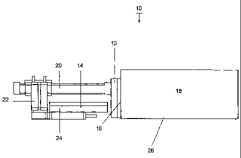
The gripper system 10 shown in Figures 1 to 5 comprises a first surface
suction
gripper 12 and a second surface suction gripper 14. The first surface suction
grip-
per 12 has a vertically extending surface for applying suction to the front
surface
16 of a cube-shaped package 18. The package 18 is in a wall of packages (not
shown here). The second surface suction gripper 14 has a horizontally
extending
surface.
The first surface suction gripper 12 is attached to the front end - that is to
say,
facing the package 18 - of a first linear drive 20 in order to horizontally
nrove the
first surface suction gripper 12 in the effective direction of the suction
force. The
first linear drive 20 can, in turn, be vertically moved by means of a guided
cylin-
der 22.
The second surface suction gripper 14 can be moved horizontally in the same
direction as the first surface suction gripper 12 by means of a guided
cylinder 24
that extends in a vertical plane below the first linear drive 20.
In the first phase shown in Figure 1, the gripper system 10 is in its staiting
or
resting position in which the second surface suction gripper 14, the first
linear
drive 20, and the guided cylinders 22 and 24 are situated behind the first
surface
suction gripper 12, that is to say, in Figure 1, to the left of the first
surface suction
CA 02651892 2008-11-10
WO 2007/131464 PCT/DE2007/000481
8
gripper 12, and they do not protrude laterally beyond the first surface
suction
gripper 12 - as seen from the suction side of the first surface suction
gripper 12,
that is to say, from the side of the package 18. The dimensians of the surface
of
the first surface suction gripper 12 are selected so as to be smaller than the
dimen-
sions of the front surface 16 of the package 18 so that, if the package 18 is
in a
package wall, as shown in Figure 6, it can be pulled out of the wall of
packages by
means of the gripper systenl 10.
In Figure 1, the gripper system 10 has been extended with its first surface
suction
gripper 12 to the front surface 16 of the package 18 and the first surface
suction
gripper 12 exerts a suction force onto the front surface 16 of the package 18.
In Figure 2, the guided cylinder 22 is already extended slightly downwards in
order to bring the second surface suction gripper 14 into position.
In Figure 3, the second surface suction gripper 14 is extended horizontally
towards the front. At the same time, the entire gripper system 10 has been
moved
back, as a result of which the package 18 is partially pulled out of the wall
of
packages.
In Figure 4, the first surface suction gripper 12 has been retracted
horizontally by
means of the first Iinear drive 20. As a result, the second surface suction
gripper
14 is now in the area of the bottom surface 26 of the package 18. Of course,
hori-
zontal movements of the first and second surface suction grippers 12 and 14
can
also be executed in the reverse direction, overlapping in a suitable form or
simul-
taneously.
In Figure 5, the second surface suction gripper 14 is pressed by means of the
guided cylinder 22 against the bottom surface 26 of the package 18, so that a
vac-
uum can build up.
CA 02651892 2008-11-10
WO 2007/131464 PCT/DE2007/000481
9
Thanks to the great mobility of the gripper system shown in Figures 1 to 4, it
can
grip an especially wide range of packages of different sizes and different
weights.
Thanks to the compact dimensions during an empty run, packages can be pulled
out of vely difficult positions. These include especially the removal of
packages
from a space that is loaded up to the ceiling.
The movements are generated by pneumatic parts. These parts are operated at a
maximum pressure of 10 bar. The first and second surface suction grippers 12
and
14 secure the package by building up a vacuum between the package and a suc-
tion mat. The vacuum is generated by means of venturi tubes.
The attachment of the gripper system to a robot flange can be adapted to
various
requirements.
A laser scanner (not shown here) detects the lower edges of the packages and
steers the robot to a suitable contact point.
Figures 6 to 13 show another special embodiment of a gripper system according
to
the present invention, whereby Figures 6 to 9 show the gripper system 100
during
use in a wall of packages in various phases, and Figures 10 to 13 show the
same
gripper system in the same phases, but without the wall of packages. For the
rest,
Figures 14 and 15 each show a front view of the gripper system in the starting
or
resting position, and in the gripping position.
As Figures 6 to 15 show, the gripper system 100 has a first suction cup
gripper
112 with several suction cups of which only two are provided with the
reference
numerals 114 and 116, said gripper having a surface that extends vertically in
the
starting or resting position, and it has a second suction cup gripper 118 with
sev-
eral suction cups of which only two are provided with the reference numerals
120
and 122, whose surface extends horizontally in the starting or resting
position,
whereby the suction cups 120 and 122 face upwards, whereas the suction cups
CA 02651892 2008-11-10
WO 2007/131464 ACTl0E20071000481
114 and 116 face forward, that is to say, in the direction of the front 124 of
a
package 126. The first suction cup gripper 112 is attached to a base 128 on
which
the second suction cup gripper 118 is also arranged in such a way that it can
be
displaced in parallel by means of two hinged column pairs 130 or 132. For this
5 purpose, each hinged column pairs 130 or 132 is associated with a pneumatic
cylinder 134 or 136. The pneumatic cylinder 134 or 136 as well as the hinged
col-
umn pairs 130 or 132 are each affixed to the base 128 in an articulated
manner.
The other ends of the hinged column pairs 130 or 132 are each affixed
laterally to
the second suction cup gripper 118 in an articulated manner. The other end of
10 each pneumatic cylinder 134 or 136 is affixed to one of the hinged columns
of the
hinged column pairs 130 and 132 in an articulated manner. In the starting or
rest-
ing position of the gripper system 100 shown in Figures 6 and 10, the gripper
system is so compact that - as shown in Figure 6- a package 126 that is posi-
tioned a bit further back than the rest of the packages can also be gripped by
its
front surface 124 by means of the first suction cup gripper 112. This is
achieved in
that the hinged column pairs 130 and 132 as well as the pneumatic cylinders
134
and 136 are arranged laterally and the second suction cup gripper 118 is
arranged
in such a way that, as seen from the suction side of the first suction cup
gripper
112, that is to say, from the package 126, these do not protrude laterally
beyond
the first suction cup gripper 112.
In Figure 6, the first suction cup gripper 112 is used to apply suction to the
fi=ont
surface 124 of the package 126 and to pull it backwards out of the wall of
pack-
ages (in Figure 10, towards the left).
In Figures 7 and 11, the pneumatic cylinders 134 and 136 are already somewhat
retracted, so that the second suction cup gripper 118 is already being moved
diagonally downwards.
In Figures 8 and 12, the pneumatic cylinders 134 and 136 are even further
retracted, as a result of wliich the hinged columns are spread and a parallel
dis-
CA 02651892 2008-11-10
WO 2007/131464 PCT/DE2007/000481
11
placement is effectuated. The result is that the second suction cup gripper
118 is
moved even ftirther in the direction of the package 126 and is moved under its
bottom surface 138.
In Figures 9 and 10, the second suction cup gripper 118 has been moved so far
out
of its starting or resting position into the gripping position that it is now
in contact
with the bottom surface 138.
The gripper system 100 can be rotated by 180 in order to grip packages that
are
ceiling-high, that can be reached normally or that are on the floor. The
pneumatic
cylinders 134 and 136 generate only the force needed for repositioning the
second
suction cup gripper 118. In its gripping position, the gripper system 100 is
self-
reinforcing since a horizontal movement by the package to which suction has
been
applied is avoided and thus no vertical displacement is possible. If the
gripper
system 100 is rotated by 180 and opened, then the second suction cup gripper
118 is suspended in its position and remains there witliout any fiirther
exertion of
energy. The drives and the direction-indicating elements are arranged on the
side.
A package in a corridor can likewise be reached since, in the starting or
resting
position of the gripper system 100, the front surface of the smallest package
is not
exceeded.
The features of the invention disclosed in the present description, in the
drawings
and in the claims can be essential either individually or in any desired
combina-
tion for the implementation of the invention in its various embodiments.