Note: Descriptions are shown in the official language in which they were submitted.
CA 02651958 2008-11-12
WO 2007/145697 PCT/US2007/008204
DIRECTED-FLOW ASSAY DEVICE
TECHNICAL FIELD
The present invention relates generally to immunoassays, receptor-, cellular-,
and
molecular-based assays, and liquid delivery devices incorporating the same.
More
specifically it relates to an analytical assay or test device containing a
liquid delivery element
and may contain reagents for detection of an analyte of interest.
BACKGROUND ART
Various chromatographic and microfluidic immunoassay techniques have been
available for some=tirne. For example, immune-based latex agglutination tests
for detecting a
factor associated with rheumatoid arthritis were used as early as 1956 (Singer
et al., Am. J.
Med. 22:888-892 (1956)). Tests that can be perforzned with such
chromatographic and fluid
systems often involve immunoassays, which depend on the specific interaction
between an
antigen and a corresponding antibody. Immunoassays therefore have gained
consideration as
an important and convenient means of testing for the presence or the amount,
or both, of
clinically important molecules.
Among the many analytical systems used for detection of analytes, particularly
those
of biological interest, are chromatographic and fluidic assay systems. Among
the analytes
frequently assayed with such systems are: (1) hormones, such as human
chorionic
gonadotropin (hCG), which is frequently assayed as a marker of human
pregnancy; (2)
antigens, particularly antigens specific to bacterial, viral, and protozoan
pathogens, such as
streptococcus, hepatitis virus, and giardia; (3) antibodies, particularly
antibodies induced as a
1730-62W0 -1-
CA 02651958 2008-11-12
WO 2007/145697 PCT/US2007/008204
result of infection with pathogens, such as bacteria or viruses, such as HIV;
(4) other
proteins, such as hemoglobin, frequently assayed in determinations of fecal
occult blood, an
early indicator of gastrointestinal disorders such as colon cancer; (5)
enzymes, such as
aspartate aminotransferase, lactate dehydrogenase, alkaline phosphatase, and
glutamate
dehydrogenase, frequently assayed as indicators of physiological function and
tissue damage;
(6) drugs, both therapeutic drugs, such as antibiotics, tranquilizers, and
anticonvulsants, and
illegal drugs of abuse, such as cocaine, heroin, and marijuana; (7) vitamins;
and (8) nucleic
acid material.
Such chromatographic systems are frequently used by physicians and medical
technicians for rapid in-office diagnosis. They are therefore commonly
referred to as "point
of care" (POC) devices. These tests may also be used for therapeutic
monitoring of a variety
of conditions and disorders. They are also increasingly used by: patients
themselves for at-
home monitoring of such conditions and disorders; scientists for use in field
testing for
transgenic crops and environmental contaminates; soldiers in battlefield
conditions for
biological warfare weapon detection; and veterinary and emergency technicians
where rapid
testing is crucial.
The chromatographic and fluidic techniques used in conjunction with most
conunon
immunoassays involve the principle of immunochromatography. In general, this
technique
uses a label or indicator particle that has been linked to an immunoprotein
specific for the
molecule to be assayed. The label and antibody/antigen together are referred
to as a
conjugate, which is then mixed with a specimen. If the analyte molecule is
present in the
specimen, the conjugate specifically binds to the molecule. The label aspect
provides a
detectable indication that the molecule to be assayed is present. The specific
reactions that
1730-62W0 -2-
CA 02651958 2008-11-12
WO 2007/145697 PCT/US2007/008204
are employed vary with the nature of the molecule being assayed and the sample
to be tested.
Such determinations are readily made depending on the molecule of interest.
Immunochromatographic and fluidic assays fall into two principal categories:
"sandwich" and "competitive," according to the nature of the antigen-antibody
complex to be
detected and the sequence of reactions required to produce that complex. In
the case of
antigen detection, the sandwich immunochromatographic procedures call for
mixing the
sample that may contain the analyte to be assayed with antibodies to the
analyte. These
antibodies are mobile and typically are linked to a label or a reagent, such
as dyed latex, a
colloidal metal sol, or a radioisotope. This mixture is then applied to a
chromatographic
medium containing a band or capture zone. This band or capture zone contains
immobilized
antibodies for the analyte of interest. The chromatographic medium can also be
in the form of
a strip resembling a dipstick. When the complex of the molecule to be assayed
and the
labeled antibody reaches the zone of the immobilized antibodies on the
chromatographic
medium, binding occurs, and the bound-labeled antibodies are localized at the
zone. This
indicates the presence of the molecule to be assayed. This technique can be
used to obtain
qualitative results. Examples of sandwich immunoassays performed on test
strips are
described in U.S. patents 4,168,146 to Grizbb et al., 4,366,241 to Tom et al.,
6,017,767 and
5,998,220 to Chandler; and 4,305,924 to Piasio et al.
In competitive or indirect immunoassays, the immobilized component is
typically
present in controlled amounts and the mobile component is present in unknown
amounts. The
unknown amount of mobile component is supplemented with a known amount of the
same
component that has been tagged by the addition of a measurable constituent
which does not
interfere with its immunochemical reactive properties. The tag may consist of
a radioisotope,
1730-62W0 -3-
CA 02651958 2008-11-12
WO 2007/145697 PCT/US2007/008204
a chromophore, a particle, a fluorophor, or an enzyme. The amount of tagged
material bound
immunochemically to the solid phase will depend upon the amount of untagged
component
in solution competing for the same binding sites. The more of the unknown
component
present, the less will be the amount of bound tagged component. As such a
relative
determination can be made.
Enzyme-based chromatographic assays have gained use in addition to
immunochromatographic assays. These enzyme-based assays involve an
enzymatically-
catalyzed reaction instead of an antigen-antibody reaction. The enzymatically-
catalyzed
reaction frequently generates a detectable product.
Although useful, currently available chromatographic techniques using test
strips have
a number of drawbacks. Some samples, for example, fecal samples, contain
particulate matter
that can obscure or color the pores of the chromatographic medium, greatly
hindering
detection of the labeling reagents. Blood for example, obviously contain cells
and colored
components that obscure the color generation in the test, and therefore make
it difficult, if not
impossible, to read. Blood cells also tend to clog the pores in the medium.
Wet
chromatographic medium is also sometimes difficult to read because of specular
reflection
from the chromatography medium. There are various other drawbacks to
chromatographic
techniques, including physical properties of lateral flow, fluid front
movement along the strip,
and color generation intensity and location.
Sample preparation and waste generation are responsible for other problems
with
currently available devices and techniques for fluidics and
immunochromatography. The
increased prevalence of diseases spread by infected blood and blood fractions,
such as HN
and hepatitis, has only exacerbated these concems. The available forrns of
lateral flow
1730-62wo -4-
CA 02651958 2008-11-12
WO 2007/145697 PCT/US2007/008204
devices have a large portion of their components that are only used for
mechanical support of
the chromatographic membrane, and are not sealed. Therefore disposal is a
concern,
expensive, and possibly hazardous because of the presumed bio-hazards.
Precautions have to
be taken so that workers, or people who may inadvertently come into contact
with the waste,
do not themselves become contaminated.
One common aspect of known devices, particularly in lateral flow technology
and
microfluidic systems, is that the assay is read visually, that is, by means of
one or more
optically readable lines on a test strip held in a carrier or through
"windows" in the device,
which may have various configurations. As briefly indicated above, there are
several
limitations or disadvantages to the known optically detected assays. Because
they are optical,
only surface changes (typically coloration) can be detected. In addition,
these tests are only
appropriate where the sample solution is colorless. Also, the target analytes
may be in the
sample solution but of such a low concentration that only relatively few are
captured in the
capture zone of the assay. This may provide a faint or even non-optically
detectable reading,
and a false negative reading can result. Quantitative assessments are only an
estimation based
on color intensity of the detection line. Because the prior art assays are
optically read, they
are subject to contamination by exposure and light-caused degradation.
Therefore, they have
a limited archival shelf life.
Typically one end of the test is exposed to the sample, normally a fluid of
some type,
being tested for the particular target analytes of interest. The fluid
migrates through a
capillary or chromatographic medium whereby the analyte with its label is
captured and
immobilized, while the remaining fluid is absorbed into a medium at the distal
end of the
assay. Examples of optically read lateral flow devices and methods are shown
in U.S. patents
1730-62W0 -5-
CA 02651958 2008-11-12
WO 2007/145697 PCT/US2007/008204
5,591,645; 5,798,273; 5,622,871; 5,602,040; 5,714,389; 5,879,951; 4,632,901;
and
5,958,790.
Many current devices also have a liquid sample application member in direct
fluid
communication with the test strip. Typically this member is made from an
absorbent material
that may be contained within the device itself, or may protrude from the
device to be more
easily introduced- to the liquid sample. The absorbent liquid sample
application member
attempts to control the rate of flow of fluid through the device. The concern
is that if the
liquid sample is applied directly to the test strip, the strip may be easily
flooded and the assay
rendered ineffective. Also the application member is usually made from a
different material
than the test strip itself due to the relatively large quantity of liquid that
it is expected to
manage.
Others have attempted to control the rate of fluid flow to the test strip by
employing
capillary assay formats. Examples of capillary assays can be found in U.S.
patents 4,883,760
and 5,474,902. However, these are not an appropriate scale for use in point-of-
care
situations.
Biological systems other than lateral flow immunoassays have employed magnetic
particles or microbeads, which may be more specifically referred to as
superparamagnetic
iron oxide impregnated polymer beads. 'These beads bind with the target
analytes in the
sample being tested and are then typically isolated or separated out
magnetically. Once
isolation has occurred, further testing may be conducted, including observing
particular
images, whether directly optically or by means of a camera. Examples of these
systems may
be found in U. S. patents 3,981,776; 5,395,498; 5,476,796; 5,817,526; and
5,922,284.
1730-62W0 -6-
CA 02651958 2008-11-12
WO 2007/145697 PCT/US2007/008204
Another apparatus for detecting target molecules in a liquid phase is shown in
U.S.
patent 5,981,297 where magnetizable particles are employed and the output of
magnetic field
sensors indicates the presence and concentration of target molecules in the
sample being
tested. Other examples to sense magnetically using physical forces are
disclosed in U.S.
patents 5,445,970; 5,981,297; and 5,925,573. However, in these devices, the
magnet requires
relatively high power because the gap where the assay is placed must be wide
enough to
accommodate the relatively thick assay device.
Accordingly, it would be advantageous to have a testing device where the fluid
sample is applied in such a manner that avoids the problems of prior art
devices, that has a
detection region providing standardized, reliable, and reproducible results,
and that is also
archival for storage over time. The present invention satisfies these needs
and provides
related advantages as well.
DISCLOSURE OF INVENTION
The present invention relates generally to immunoassays, cellular- and
molecular-
based assays. More specifically, it relates to directed flow assays that have
a sample receiving
port separated by a micro-channel from the analytical membrane. In preferred
embodiments,
these assays use superparamagnetic particles as the labels for the analytes to
be detected. The
bound complexes of labeled particles and analytes are captured in
predetermined areas or
regions on the test strip and the presence and quantity of labeled analytes
are then detectable
by magnetic means. It is also contemplated in some embodiments that the
analytes may be
detected by routine optical means, for example. Specific reagents and
conjugates necessary
for optical detection have been in use for many years and are well known.
1730-62W0 -7-
CA 02651958 2008-11-12
WO 2007/145697 PCT/US2007/008204
In one embodiment, the device has an assay support member having a first end
and a
second end and a porous analytical membrane mounted adjacent to and generally
parallel
with the support member. The analytical membrane has a first end and a second
end, and at
least one capture region intermediate the flrst and second ends where at least
one capture
region is configured to capture labeled analytes moving from the first end of
the analytical
membrane toward the second end of the analytical membrane.
The devices herein also preferably have a sample receiving port, preferably
connected
via a channel, or in fluid communication with, the test strip itself. In these
embodiments, a
sample application member, or sample pad, is not strictly necessary. The
sample receiving
port has an appropriate size and construction to hold a desired amount of
fluid and is in direct
fluid communication with the test strip. The sample receiving port is at one
end of the
support member for introduction of the sample to be analyzed to said device.
The sample
receiving port has a fluid sealing material, and a channel layer positioned
adjacent the sealing
material. The channel layer has an opening therein and also a channel, such
that the opening
provides fluid communication with the channel, and such that the channel
provides fluid
communication with the porous analytical membrane. A hydrophilic material is
positioned
over the channel layer and has an opening therein corresponding to the opening
of the
channel layer. A gasket element is positioned over the hydrophilic material
and has an
opening therein to allow fluid entry into the port. The gasket provides a seal
between the
assay and any surrounding housing.
Additional embodiments of the invention may have a protective membrane
covering
the analytical membrane on the side opposite to the support member. The
protective
1730-62W0 -8-
CA 02651958 2008-11-12
WO 2007/145697 PCT/US2007/008204
membrane may be optically non-tra.nsparent. In other embodiments the
protective membrane
is formed integrally with the porous membrane. Altematively, the protective
membrane may
be formed pursuant to a surface treatment of the porous membrane.
Additional embodiments of the invention may have a control region in the
porous
membrane for collection of magnetic conjugates that have passed the capture
region to show
that the test strip has been used. In additional embodiments at least one
magnetic calibration
area may be printed on the protective membrane. The calibration area may have
the form of a
line, or even a single dot, among others.
Preferred embodiments of the invention have a bottom housing portion for
supporting
the support member. This housing will preferably be in a C-shape, although
many other
shapes are contemplated herein as long as access by a reader device to the
test strip is
provided. A top housing portion may also be present in these embodiments. This
top housing
portion preferably has a complementary configuration to the bottom housing
portion and fits
over the bottom housing portion such that the immunoassay test strip spans the
opening of, or
the arms of, the C-shape.
The invention further provides various methods employing the devices described
herein. For example, a method is provided for conducting lateral flow
immunoassay
quantitative detection of target analytes in a sample. The method involves
coupling
superparamagnetic conjugate particles configured to bind with a desired target
analyte in the
sample. The analyte and superparamagnetic particle complex is applied to one
end of the
assay and delivered to the porous membrane of a lateral flow test strip
through a sample
receiving port. The complexes of analyte and superparamagnetic particles move
through the
porous membrane by capillary action. Next, the quantity of labeled analytes in
the capture
I730-62W0 -9-
CA 02651958 2008-11-12
WO 2007/145697 PCT/US2007/008204
region is read by means of a magnetic assay reader device.
The present invention has improved sensitivity over known lateral flow
devices. It
provides a very rapid (within a few minutes) analytical measurement. There are
many
advantages of using magnetic particles over known colored particles or other
optical
indicators in the prior art. These include quantitative linearity of magnetic
detection with
respect to the amount of magnetic material present over a wide range, through
at least four
orders of magnitude. Time stability is also superior because magnetic
particles are stable,
thereby allowing the developed assay to be archived and retested as necessary.
Further,
magnetic particles are generally inert to biological systems and to the
environment. So they
not only remain stable, they are environmentally and biologically safe.
Further, magnetic
particles are already in widespread use with other technologies throughout the
diagnostics
industry so they are readily available. Other benefits of magnetic detection
are that since the
particles are superparamagnetic, they are magnetic only when exposed to a
magnetic field.
This allows them to be freely manipulated in solution without aggregating.
Another significant advantage over the prior art optical lateral flow devices
is that
with this invention the total amount of analytes in the capture region of the
test strip is
measured as a single mass in one volumetric measurement. The permeability of
magnetic
fields is such that any analyte contained within the active region of the
detector will be
measured. This contrasts with optical sensing techniques in which only
reporter-analyte
interactions on or very near the surface of the strip are detectable. In this
invention the
strength of the magnetic signal increases directly with the mass of iron
involved, unrelated to
its proximity to the surface of the strip. This inherent linearity of magnetic
detection
contributes to increased sensitivity, accuracy, and dynamic range.
Additionally,
1730-62W0 -10-
CA 02651958 2008-11-12
WO 2007/145697 PCT/US2007/008204
superparamagnetic particles are physically similar to colloidal gold with
regard to size, and
may be easily adapted to a wide range of lateral flow assays. It is noted that
colloidal gold, as
well as fluorescent latex particles, are typically employed in the prior art
optically sensed
iminunological assays.
In most lateral flow devices, typically at one end of the porous membrane is
the
sample introduction area. This is conventionally made up of a sample pad and a
conjugate
pad. In the prior art, the conjugate pad is the source of freely moveable
colored particles,
typically gold sols from colloidal gold, or fluorescent latex particles. In
various
embodiments of the present invention, there is no sample pad or conjugate pad.
The
moveable particles are the superparamagnetic particles which label the target
analytes from
the sample being introduced through the fluid channel. In preferred
embodiments herein, the
sample is mixed with the superparamagnetic particles before the sample is
applied to the
device, or at the same time. Various functional advantages exist with this
configuration. For
example, the reaction kinetics of particles in solution assures that the
reaction is faster,
provides more complete incubation, and runs to completion. By contrast, when
the reaction
proceeds in a wave front on a porous membrane, the reaction tends to be slower
and the
possibility exists that it will not reach an end point as fast, or at all.
The sample, together with the bound magnetic particle labels and target
analytes,
move with capillary action along the porous membrane and are captured in a
predefmed
location called a capture region or capture zone. There may be more than one
capture zone to
enable multiplexing. As used herein, the term "multiplexing" refers to testing
for more than
one type of analyte at the same time in the same test strip. Excess analytes
and the carrying
liquid continue to move on through the capture zone to the other end of the
porous
1730-62W0 -11-
CA 02651958 2008-11-12
WO 2007/145697 PCT/US2007/008204
membrane, sometimes forming a control line or zone separate from the capture
zone. An
added feature is that typically a wicking pad is mounted on the far end of the
porous
membrane to enhance the capillary action by driving the flow from the
introduction at one
end of the porous membrane through the entire length of the membrane.
In the embodiments herein not using optical detection, the top of the porous
member
may be covered by another protective sheet or membrane which is not
transparent. It may be
completely opaque. This top sheet may also include pre-printed
standards, which are employed for calibrating purposes so that the magnetic
detector can be
calibrated for each test to ensure complete accuracy. The protective sheet may
not be a
separate element in some cases, but may only be the upper surface of the
membrane properly
treated to function as a protective sheet or surface.
BRIEF DESCRIPTION OF DRAWING
These and other aspects, features and advantages of the present invention will
become more apparent upon consideration of the following description of
preferred
embodiments taken in conjunction with the accompanying drawing, in which like
reference
numerals designate like parts throughout:
FIG. 1 is an exploded perspective view of a directed flow assay device in
accordance
with the present invention;
FIG. 2 is a side sectional view of the assembled test strip of FIG. 1;
FIG. 3 is a perspective view of the bottom housing portion of the device of
1730-62W0 -12-
CA 02651958 2008-11-12
WO 2007/145697 PCT/US2007/008204
FIG. 4 is a perspective view of the inside of the top housing portion of the
device of
FIG.1; and
FIG. 5 is a perspective view of the fully assembled device of the present-
invention.
BEST MODE FOR CARRYING OUT THE INVENTION
In the following description of preferred embodiments, reference is made to
the
accompanying drawings, which form a part hereof, and which show by way of
illustration,
specific embodiments of the invention. It is to be understood by those of
working skill in this
technological field that other embodiments maybe utilized, and structural, as
well as procedural
changes may be made without departing from the scope of the present invention.
With reference now to FIGS. 1 to 5, directed flow assay device 10 in
accordance with the
present invention comprises immunoassay test strip 12, which has porous
analytical membrane
14 mounted adjacent to and generally parallel with support member 11. Adhesive
layer 13 (FIG.
2) anchors analytical membrane 14 to support member 11. The analytical
membrane has a first
end and a second end.
Superparamagnetic particles (not shown) may be present in the sample
preparation
outside the device. These particles are configured to bind with the target
analytes in the sample.
The membrane has a capture region intermediate to the first and second ends of
the analytical
membrane. The capture region generally has control and detection regions 28,
shown in FIG. 1.
The capture region is configured to capture labeled analytes moving from the
first end of the
analytical membrane toward the second end of the analytical membrane.
Additional regions may
be present, if desired, for example, for calibration. See, for example,
calibration strips 25 (Figs.
1 and 2) on protective membrane 24. This could equally be a dot, such as dot
27 in Fig. 5. As
1730-62wo -13-
CA 02651958 2008-11-12
WO 2007/145697 PCT/US2007/008204
shown in Fig. 2, it could be either a line or a dot.
One aspect of the present invention is that it has sample receiving port 30 at
one end of
strip 12 for introduction of the sample to be analyzed. In prior devices, the
sample receiving port
is generally formed by the housing of the device, if at all. In the present
invention, the sample
receiving port is located generally on the strip, and is made or built up from
layers of applied
material.
The sample receiving port is formed by fluid sealing materia115 on the bottom,
which is
positioned over the support member. Preferably fluid sealing material 15 is
hydrophilic. Layer
18 is positioned over the fluid sealing material and has channel 16 and
opening 19 formed
therein. Channel 16 extends longitudinally along the strip to.direct fluid
toward the capture
region of the device. Generally the channel is constracted of sufficient
dimension and
configuration to allow sufficient fluid flow without fluid leakage out of the
sides or without
exhibiting clogging or clumping, as might otherwise occur with more viscous
samples, such as
blood. Although FIG. 1 shows channel 16 being somewhat narrower than opening
19, it is
contemplated herein that channel 16 could be the same width or even wider than
opening 19.
Alternatively, channel 16 could have a wider opening distal to the sample
receiving port than its
width proximal to the sample receiving port. This variation could be
particularly useful in the
case where clotting or clumping of the sample is of concem.
Once built up in layers, the sample receiving port is formed. The port
provides fluid
communication with the channel, and the channel provides fluid communication
with the
analytical membrane. Next hydrophilic material 20 is positioned over layer 18,
the hydrophilic
material having an opening therein corresponding to opening 19, but covering
channel 16.
Gasket element 22 is positioned over hydrophilic material 20 and has an
opening therein
1730-62W0 -14-
CA 02651958 2008-11-12
WO 2007/145697 PCT/US2007/008204
corresponding to opening 19 to allow fluid entry into the port. The gasket
provides a fluid seal
between the assay and any surrounding housing.
In various embodiments described herein, the housing is made up of bottom
housing
portion 8 which supports support member 11. As shown in FIG. 3 it also
preferably has side tabs
6 for proper placement in a magnetic reader device. Bottom housing portion 8
is generally
configured in a C-shape, the open side being designated by reference numeral
46. FIG.4shows
the underside of top housing portion 42. It is generally complementary in
configuration to the
bottom housing portion. Therefore, it is also in a C-shape configuration. The
top housing fits
over the bottom housing such that test strip 12 spans opening 46 of the C-
shape, as shown in the
assembled device of FIG. 5. Thus, a magnetic reader device can access test
strip 12 from the top
and bottom surface at the same time. FIG. 2 shows a sectional side view of
assembled test strip
12. Wicking pad 26 is present on one end, as well as protective membrane 24,
which covers
analytical membrane 14.
Since test strip 12 spans opening 46 of the assembled housing portions, and
since it is
placed in the gap of a magnetic reader device, it is of concern that the test
strip be properly
anchored within the housing so as to avoid flexing or movement of the strip
with relation to the
housing portions. It is also important that the relative positions of the
control line, index line,
and result lines be maintained. Accordingly, the embodiments of the present
invention have
gripping and tensioning aspects to control these effects.
With reference again to FIG. 3, bottom housing portion 8 is shown in a
perspective view.
Although not shown in this view, test strip 12 is dropped into trough 56.
Preferably the width of
the trough will accommodate the width of the strip without binding or without
undesired lateral
movement. Cross channels 58 are present in the bottom of trough 56. There are
preferably two
1730-62W0 -IS-
CA 02651958 2008-11-12
WO 2007/145697 PCT/US2007/008204
such cross channels closely spaced at one end, and one cross channel at the
other end of the
trough. Also at one end of the trough there is sloping cross channel 59. These
channels are
configured to accommodate corresponding features on the underside of top
housing portion 42
when assembled. Accordingly, the assembly thereofprovides a gripping and
tensioning aspect to
the test strip. I
As shown in FIG. 4, the underside of top housing portion 42 has pegs 64, two
on one end,
and one on the other end of the device. Also on one end of the device is
tensioner 62.
Tensioner 62 is shown with a downward sloping face and a scalloped or ridged
protruding edge.
This edge contacts the test strip and provides an appropriate degree of
tension without causing
deformation or tearing of the strip. The configuration shown is by way of
example and the
tensioner may have other equally effective shapes.
Other features of the device are directed toward preventing movement of the
strip in
relation to the magnetic field. For example, bottom housing portion 8 has
securing holes 54 for
receiving securing pins 65 on top housing portion 42. The relatively large
diameter of the hole
and pin secures the parts together to prevent undesired warping or bending of
the housing
components once assembled. Also it can be seen in FIG. 3 that assembly holes
53 in the bottom
housing portion are configured to receive assemblypins 67 in the top housing
portion, preferably
with a compression fit.
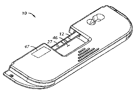
As mentioned above, FIG. 5 shows an embodiment of the device fully assembled.
Test
strip 12 is shown spanning opening 46. Barcode label area 47 on top housing
portion 42
provides information that the magnetic reader device uses in the assay, such
as calibration and
positional information. It also may provide information regarding the nature
of the particular test
or sample being tested for.
1730-62W0 -16-
CA 02651958 2008-11-12
WO 2007/145697 PCT/US2007/008204
It should be observed that while the above description generally relates to
quantitative
detection of target analytes in a directed flow immunoassay, the invention can
equallybe used for
receptor assays, cellular assays, or molecular assays.
Even though numerous characteristics and advantages of the present invention
have been
set forth in the foregoing description, together with details of the structure
and function of the
invention, the disclosure is illustrative only, and changes may be made in
detail, especially in
matters of shape, size, and arrangement of parts within the principles of the
invention to the full
extent indicated by the broad general meaning of the terms in which the
appended claims are
expressed.
1730-62WO -17-