Note: Descriptions are shown in the official language in which they were submitted.
CA 02651969 2014-10-08
Inner Panel for a Door Assembly Having an Integrated Intrusion Beam
FIELD OF THE INVENTION
The present invention relates to a module for a motor vehicle door body.
More particularly, the present invention relates to a structural module that
both
strengthens the motor vehicle door body, reduces the packaging sizc of the
door and
acts as a hardware carrier for hardware subsystems in order to minimize
subsequent
assembly operations.
BACKGROUND OF THE INVENTION
A motor vehicle door typically includes an outer sheet metal panel and an
inner sheet metal panel connected together to form a cavity therebetween. An
equipment module is often mounted to the inner sheet metal panel within the
cavity.
In addition, an impact beam is typically welded to the inner sheet panel to
resist
deformation of the door during a side impact collision. The use of equipment
modules and side impact beams increases the thickness of the door, and can
increase
assembly costs of the vehicle door.
U.S. Patent No. 7,040,688 to White and Chernoff,
, discloses the use of an inner door panel having an integrated impact beam.
The inner panel is formed to include corrugated regions that extend convexly
outwards from its wet side surface (i.e., facing towards the exterior of the
vehicle).
The corrugated regions provide sufficient intrusion resistance to obviate the
need for
an additional impact beam. To accommodate equipment mounted to the wet side
surface of the inner panel (such as the rails to the window regulator),
interruptions in
the corrugated regions are provided.
While the above-noted inner door panel disclosed by White and Chernoff
improves the strength and reduces the thickness of the door assembly relative
to a
conventional vehicle door, it is not without its drawbacks.
First, the corrugated regions of the integrated impact beam are limited in
their
size and geometry as to accommodate wet-side mounted equipment, such as
providing
space between the outer sheet metal and the panel for the travel of the window
glass.
1
CA 02651969 2008-11-12
WO 2007/131332 PCT/CA2007/000808
Furthermore, the corrugated regions must be spaced apart from the outer panel
as to
allow free travel of the window glass.
Second, the inner panel has a large hole in it to accommodate the window
regulator drive assembly. This has a deleterious effect on the structural
integrity of
the inner door panel, causing the design to use many more corrugations to
achieve a
particular side impact resistance. In addition, despite the large access hole
for the
window regulator motor assembly, the door assembly does readily enable certain
door
hardware such as the window regulator subsystem to be installed on a high
speed
manufacturing line. Moreover, the White and Chernoff inner panel must still be
sealed to prevent moisture and road dirt from entering the passenger cabin.
It is thus desirable to provide a door assembly that includes an inner door
panel that provides a high level of intrusion resistance but still allows for
hardware
components to be easily mounted while minimizing the thickness of the door
assembly.
SUMMARY OF THE INVENTION
According to one aspect of the invention, an inner panel having an integrated
impact beam is provided for a motor vehicle door assembly, wherein the inner
panel
substantially seals the motor vehicle passenger cabin from the external
environment.
According to another aspect of the invention, an inner panel having an
integrated impact beam is provided for a motor vehicle door assembly, wherein
a
latch is mounted within a cavity on a dry side of the inner panel, facing the
passenger
cabin.
According to yet another aspect of the invention, there is provided a door
assembly that includes integral impact resistant regions. The door assembly
includes
an outer panel and an inner panel, operably connected to the outer panel so
that a
cavity is formed therebetween. At least one hardware mounting surface is
integrally
formed from the inner panel and extends towards the outer panel. Each of the
hardware mounting surfaces is operable to mount a hardware component between
the
inner and outer panels. At least one integrally-formed impact region is
provided on
the inner panel that is operable to strengthen the door assembly and increase
its
intrusion resistance of the vehicle door during a collision. The at least one
impact
2
CA 02651969 2014-10-08
region is displaced at least as far away from the outer panel as the at least
one
hardware mounting surface.
BRIEF DESCRIPTION OF THE DRAWINGS
Preferred embodiments of the present invention will now be described, by way
of example only, with reference to the attached Figures, wherein:
Figs. 1A and 1B are perspective views of a door assembly according to a first
embodiment of the invention;
Fig. 2 is a perspective view of the door assembly shown in Figs. IA and 1B
with a trim component removed;
Fig. 3A is a perspective view of the dry side of an inner panel for the door
assembly shown in Figs. lA and 1B;
Fig. 3B is a perspective view of the wet side of the inner panel for the door
assembly shown in Figs. IA and 1B;
Fig. 4A and 4B are perspective views of a door assembly (without trim)
according to a second embodiment of the invention, Fig. 4A showing the dry
side of
the inner panel and Fig. 4B showing the wet side of the inner panel;
Figs. 5A and 5B are partially exploded views of the second embodiment
showing a hardware carrier which is insertable in the compartment between the
inner
and outer door panels;
Figs. 6A and 6B are detail views of a window regulator motor assembly
employed by the second embodiment; and
Fig. 7 is a partially exploded view of a door assembly according to a third
embodiment, showing a variant of the hardware carrier which is insertable in
the
compartment between the inner and outer door panels.
DETAILED DESCRIPTION OF THE PREFERRED EMBODIMENTS
Referring now to Figs 1A, 1B and 2, a first embodiment of a door assembly is
shown generally at 10. Door assembly 10 includes an exterior-facing "wet side"
(Fig.
1A) and an interior-facing "dry side" (Fig. 1B). Door assembly 10 includes an
outer
panel 12, inner panel 14 operably connected to outer panel 12 as to form a
compartment therebetween, and at least one trim component 16. A plurality of
3
CA 02651969 2008-11-12
WO 2007/131332 PCT/CA2007/000808
components are mounted to door assembly 10, including a side mirror 18, latch
assembly 20, speaker 22, inner handle assembly 24 (Fig. 2), outer handle
assembly
26, electrical wiring harness 28, door hinges 30 and a window regulator motor
32
operable to power a window regulator (not shown) to raise or lower a window
glass
(also not shown). A set of hinges 33 are provided to operably connect door
assembly
to a motor vehicle (not shown). The presently-illustrated door assembly 10 is
frameless, but framed door assemblies are also within the scope of the
invention.
Outer panel 12 is shaped to present a streamlined and contoured exterior
surface. Inner panel 14 provides a generally complementary contoured surface.
10 Referring now to Figs. 3A and 3B, inner panel 14 is described in greater
detail. Inner
panel 14 includes an inboard panel region 34 that is displaced away from the
outer
panel 12 by web portions 36 to form the compartment. A flange 38 is provided
along
the edges of inner panel 14 to provide a positive contact surface for bonding
to outer
panel 12 by welding, hemming, or fastening. Inner panel 14 is generally around
2
mm thick and is preferably manufactured from an aluminum-magnesium sheet stock
such as AA 5083 H18, although other suitable alloys can be used.
Inner panel 14 includes a number of integrally-formed components operable to
decrease the assembly time of door assembly 10 such as fastening locators 40
to assist
in situating inner panel 14 relative to outer panel 12 and trim fastening
locators 42 to
assist in situating trim components 16 on inner panel 14. A wiring harness
pass-thru
44 is provided to allow the passage of wiring harness 28, and a handle pass
thru 46 is
provided to allow the passage of a handle cable (not shown). On the dry side,
inner
panel 14 further includes a mounting surface 48 for an inner handle assembly
(not
shown), and a speaker housing 50. On the wet side, inner panel 14 includes a
window
regulator motor mounting surface 52, a latch attachment 54, and rail mounting
surfaces 56 to locate the rails for a window regulator (not shown). Motor
mounting
surface 52 and rail mounting surfaces 56 are raised away from inboard panel
region
34 towards outer panel 12. Other integrally-formed components for inner panel
14
will occur to those of skill in the art.
Inner panel 14 further includes at least one integral impact region 58. Each
integral impact region 58 is a corrugated portion of the inner panel,
comprising a
series of ridges and troughs. Ridges on the wet side of inner panel 14 are
troughs on
4
CA 02651969 2008-11-12
WO 2007/131332 PCT/CA2007/000808
the dry side, and troughs on the wet side are ridges on the dry side. Motor
mounting
surface 52 and rail mounting surface 56 extend closer towards outer panel 12
than the
ridges of the impact regions 58 towards outer panel 12. Preferably, ridges
facing the
wet side are at least as far away from outer panel 12 as the surface of
inboard panel
region 34. Thus, packaging interference by the impact region 58 is minimized
between the wet side of inner panel 14 and outer panel 12, allowing for a
narrower
compartment between outer panel 12 and inner panel 14. Preferably, inner panel
14
includes multiple impact regions 58 running non-parallel to each other to
provide the
maximum intrusion resistance from differing impact angles. Different impact
regions
58 can have differing numbers of corrugations as to provide the desired level
of
intrusion resistance while still providing sufficient flat mounting surface
area to meet
door packaging requirements. In the currently illustrated embodiment, impact
regions
58 bisect each other in region 52 to provide the maximum intrusion resistance
at the
preferred sitting position of the vehicle occupant. The impact regions 58
extend
across a substantial length of inboard panel region 32 without interruption.
While the
intrusion resistance can vary in impact regions 58 based upon different design
requirements, testing has shown that door assembly 10 with impact regions 58
can
require approximately five times the side impact force to be displaced an
equivalent
distance in a conventional door.
According to the presently preferred embodiment of the invention, inner panel
14 is manufactured using combination of forming techniques. A blank is
preheated
(typically to a temperature between 450-550 C and placed into a multi-piece
stamping
tool to form into an intermediary shape. The raw stock is generally 2-3 mm
thick.
Apertures such as wiring harness pass-thru 44 are removed from the sheet metal
stock
and the stock is pressed into a intermediate form subject to the limitations
of stamping
and the malleability of the stock.
After passing through the warm-forming stage, inner panel 14 is further
formed by a super plastic forming operation (SPF). As known to those of skill
in the
art, the elasticity of alloys with a fine grain microstructure (such as
aluminum AA
5083 H18) can increase up to several hundred percent when exposed to high heat
and
pressure. Under high heat (typically between 400-550 C) and pressure, the
stock is
formed into the contoured shape of the mould at a controlled rate and
pressure. Using
5
CA 02651969 2008-11-12
WO 2007/131332 PCT/CA2007/000808
SPF, a deeper draw can be achieved in the stock over typical stamping
processes. By
pre-heating and pre-stamping the stock, the time required to super-plastic
form the
final shape of inner panel 12 is reduced.
Door assembly 10 reduces the part count and weight while increasing the
intrusion resistance over conventional doors. In addition, the location and
angling of
impact regions 58 provides for a thinner yet stiffer door than the prior art.
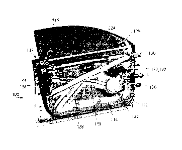
Figs. 4A, 4B, 5A, 5B show a second embodiment of a door assembly 100,
which includes an outer panel 112 and an inner panel 114, defining a
compartment
113 therebetween. The inner panel 114 includes an integrated intrusion beam
158
comprising corrugated portions of the inner panel.
In this embodiment, a cavity 154 (seen best in Fig. 5B) is formed on the dry
side of inner panel 114 for attachment of a latch 155 (seen best in Fig. 4A)
thereto. A
latch cover/reinforcement member 156 may also be optionally mounted to the
inner
panel 114. Locating the latch on the dry side of the inner panel 114 has a
number of
advantages, including eliminating access hole 54A of the first embodiment in
order to
gain access to the wet side of the inner panel, making it easier to install or
bolt the
latch to the panel. In addition, placing the latch 155 on the dry side
eliminates the
possibility of opening or tampering with the latch 155 by inserting a tool
(such as a
"slim jim") into the compartment 113 between the outer and inner panels 112,
114
through the top of the compartment 113 or window slot.
Door assembly 100 also includes a hinge reinforcement member 162 (seen
best in Fig. 4B), which is preferably adhesively bonded to the wet side of the
inner
panel 114. An epoxy adhesive has been found suitable for this purpose. Hinges
130
(see Fig. 4A) are mounted to the inner panel 114 and the hinge reinforcement
member
162.
A number of other components are bolted or otherwise fastened directly to the
dry side of the inner panel 114. These include an inner door handle 124 wiring
harness 128, and speaker 122 all of which are mounted to suitably shaped
mounting
surfaces on the inner panel 114.
The door assembly 100 of the second embodiment also employs a separate
hardware carrier 170 (seen in isolation in Fig. 5A) that carries various
hardware
components, particularly, window regulator components described in greater
detail
6
CA 02651969 2008-11-12
WO 2007/131332 PCT/CA2007/000808
below, for insertion as a unit into the compartment 113 between the outer and
inner
panels 112, 114. In the preferred embodiment, the carrier 170 includes a belt
line
reinforcement member 172 that is a structural component in that it partially
bears the
load of a side and/or frontal impact. The belt line reinforcement member 172
is
bolted to the inner panel 114 at mounting locations 174A, 174B. Locating lugs
176
are preferably provided for aligning the carrier 170 relative to the inner
panel.
The carrier 170 also carries a mirror flag 178, and an integral glass run
channel 180. These components are pre-bolted to the preferred belt line
reinforcement member 172.
The carrier 170 also holds many window regulator components. These
include window regulator rails 182, which are pre-bolted to the preferred belt
line
reinforcement member 172, or otherwise to an alternative form of hardware
carrier
170. The rails 182, in turn, carry window glass lifter plates 184, pulleys 186
and
associated cables 188. In the illustrated embodiment (Figs. 4 & 5), the only
part of
the window regulator motor assembly that is pre-connected to the window
regulator is
a cable drum 190 (seen best in Fig. 5A), which is situated on the wet side of
the inner
panel. The motor 132 and drive gear 192, and the electrical connections to the
motor
132, are situated on the dry side of the inner panel 114, and a connection is
made
between the cable drum 190 and drive gear 192. More particularly, referring to
the
detail view of Figs. 6A and 6B, the cable drum 190 is preferably disposed in a
housing 194 that includes or incorporates a series of hollow core, snap fit,
prongs 196.
The inner panel 114 features a corresponding series of vias 198 (see Fig. 5A,
5B) for
accommodating the passage of the prongs 196. The motor drive gear 192 is
disposed
in a housing 200 (Fig. 6B) which has a series of correspondingly situated
mating
receptacles 202. As the cable drum housing 194 is preferably mounted to one of
the
rails 182, which in turn are pre-mounted to the carrier 170 that is aligned on
the inner
panel 114, the drum is thus consistently aligned on the wet side of the inner
panel 114.
Hence, the assembler is able to easily align and interlock the cable drum
housing 194
with the drive gear housing 200 utilizing the snap fit connection. In the
process, an
output shaft 204 of the drive gear 192 is mated to an internal gear 206 of the
cable
drum 190 via a shaft passageway 208 located in the inner panel 114. If
desired, bolts
(not shown) may be driven through the hollow prongs 196 to seat in the
receptacles
7
CA 02651969 2014-10-08
202, thus mechanically affixing the cable drum housing 194 and the drive gear
housing 200 to the inner panel 114. In this manner, the window regulator is
easily
installed and the components of the motor assembly seal the inner panel.
The cable drum 190 may be mounted in other ways within the scope of the
invention. For example, the cable drum housing may be disposed on a web (not
shown) connected to and disposed between the rails, thereby uniquely locating
the
cable drum within the compartment 113 between the outer and inner door panels.
In a variant of the carrier 170, shown in Fig. 7, carrier 170 holds an entire
window regulator motor assembly 210, which is thus situated entirely on the
wet side
of the inner panel 114. The motor assembly 210 is ensconced within a small
cavity
212 formed in or on the wet side of inner door panel, enabling the motor
assembly
210 to be bolted to the inner panel at designated points thereat.
In either variant, the vehicle window glass 215 may be pre-installed to the
carrier 170, and the whole unit inserted into the compartment 113 between the
outer
and inner door panels 112, 114. Alternatively, the lifter plates 184 may be
snap-in
lifter plates as known in the art per se in which, once the window regulator
is installed
into the door assembly, the window glass 215 is thereafter inserted into the
lifter
plates 184 via a snap-fit connection.
It will be seen from the foregoing that the second embodiment of the door
assembly has no substantial openings or access holes therethrough, except for
minor
passageways to accommodate fasteners, wire passages or a drive-shaft. These
minor
openings do not substantially affect the rigidity or impact performance of the
inner
panel, and are easily sealed using plugs well known in the art per se.
The above-described embodiments are intended to be examples of the present
invention and those skilled in the art may effect alterations and
modifications thereto.
8