Note: Descriptions are shown in the official language in which they were submitted.
CA 02652099 2008-11-12
DESCRIPTION
Vehicle, And Its Control Method
Technical Field
[0001] The present invention relates to a vehicle and a control
method of the vehicle.
Background Art
[0002] One proposed structure of a vehicle includes an engine having
an open-close timing of an intake valve adjustable by a variable
valve timing mechanism, a planetary gear mechanism connected with
a crankshaft of the engine and with a driveshaft, a first motor
configured to input and output power from and to the planetary gear
mechanism, a second motor configured to input and output power from
and to the driveshaft, and a battery configured to transmit electric
power to and from the first motor and the second motor (see, Patent
Document 1) . The prior art vehicle of this proposed structure sets
an engine operation curve based on elapse or non-elapse of a time
period required for ensuring sufficient function of the variable
valve timing mechanism since a start of the engine and drives the
engine according to the preset engine operation curve. The engine
is thus drivable even in the condition of insufficient function
of the variable valve timing mechanism.
Patent Document 1: Japanese Patent Laid-Open No. 2004-360672
Disclosure of the Invention
1
CA 02652099 2008-11-12
[0003] In the prior art vehicle of this structure, it is desired
to prevent the driver from feeling uncomfortable or odd in the case
of operation of the engine in the vehicle stop state. The variable
valve timing mechanism may be structured to change the open-close
timing of the intake valve by utilizing a supply of oil from an
oil pump with rotation of the crankshaft of the engine. There may
be an insufficient supply of oil from the oil pump required for
changing the open-close timing of the intake valve, in some
operating condition of the engine, especially in some condition
of the rotation speed of the engine. It is accordingly desired to
appropriately control the variable valve timing mechanism by taking
into account the operating condition of the engine.
[0004] In the vehicle and the control method of the vehicle, there
would thus be a demand for reducing the driver's uncomfortable
feeling or odd feeling in the case of operation of an internal
combustion engine in a vehicle stop state. In the vehicle and the
control method of the vehicle, there would also be a demand for
adequately controlling an open-close timing change mechanism to
change an open-close timing of at least an intake valve and an
exhaust valve of the internal combustion engine by utilizing a
supply of an operating fluid with rotation of an output shaft of
the internal combustion engine.
[0005] The present invention accomplishes at least part of the
demand mentioned above and the other relevant demands by the
following configurations applied to the vehicle and the control
method of the vehicle.
2
CA 02652099 2008-11-12
[0006] According to one aspect, the invention is directed to a
vehicle including: an internal combustion engine configured to
output a power for driving the vehicle and to be drivable at any
arbitrary drive point irrespective of a driving condition; an
open-close timing change mechanism configured to change an
open-close timing of either an intake valve or an exhaust valve
of the internal combustion engine by utilizing a supply of an
operating fluid with rotation of an output shaft of the internal
combustion engine; and a controller configured, in an operation
demand for driving to give an operation demand of the internal
combustion engine for driving the vehicle, to control the
open-close timing change mechanism and the internal combustion
engine to drive the internal combustion engine at a rotation speed
of not lower than a preset first rotation speed with an open-close
operation of the intake valve or the exhaust valve of the internal
combustion engine at an open-close timing corresponding to a first
restriction, and in a vehicle stop-state operation demand to give
an operation demand of the internal combustion engine in a vehicle
stop state, to control the open-close timing change mechanism and
the internal combustion engine to drive the internal combustion
engine at a rotation speed of not lower than a preset second rotation
speed, which is lower than the preset first rotation speed, with
an open-close operation of the intake valve or the exhaust valve
of the internal combustion engine at an open-close timing
corresponding to a second restriction, which has a smaller degree
of change from a reference timing than the first restriction.
3
CA 02652099 2008-11-12
[00071 In the operation demand for driving to give an operation
demand of the internal combustion engine for driving the vehicle,
the vehicle according to this aspect of the invention controls the
open-close timing change mechanism and the internal combustion
engine to drive the internal combustion engine at the rotation speed
of not lower than the preset first rotation speed with an open-close
operation of the intake valve or the exhaust valve of the internal
combustion engine at the open-close timing corresponding to the
first restriction. The open-close timing change mechanism changes
the open-close timing of either the intake valve or the exhaust
valve of the internal combustion engine by utilizing the supply
of the operating fluid with rotation of the output shaft of the
internal combustion engine. In the vehicle stop-state operation
demand to give an operation demand of the internal combustion engine
in the vehicle stop state, on the other hand, the vehicle of the
invention controls the open-close timing change mechanism and the
internal combustion engine to drive the internal combustion engine
at the rotation speed of not lower than the preset second rotation
speed, which is lower than the preset first rotation speed, with
an open-close operation of the intake valve or the exhaust valve
of the internal combustion engine at the open-close timing
corresponding to the second restriction, which has the smaller
degree of change from the reference timing than the first
restriction. In the vehicle stop-state operation demand, the
internal combustion engine is driven at the rotation speed of not
lower than the relatively low second rotation speed. Such drive
4
CA 02652099 2008-11-12
control effectively reduces the driver's uncomfortable feeling or
odd feeling triggered by operation of the internal combustion
engine at a high rotation speed, compared with the control of driving
the internal combustion engine at a rotation speed of not lower
than the first rotation speed whether in the operation demand for
driving or in the vehicle stop-state operation demand. In the
vehicle stop-state operation demand, the intake valve or the
exhaust valve of the internal combustion engine is opened and closed
at the open-close timing corresponding to the second restriction,
which has the smaller degree of change from the reference timing.
Compared with an open-close operation of the intake valve or the
exhaust valve of the internal combustion engine at the open-close
timing corresponding to the first restriction whether in the
operation demand for driving or in the vehicle stop-state operation
demand, such drive control ensures the better open-close timing
of the intake valve or the exhaust valve of the internal combustion
engine according to the operating condition of the internal
combustion engine and the more appropriate control of the
open-close timing change mechanism.
[0008] In one preferable application of the vehicle according to
the above aspect of the invention, in the operation demand for
driving, the controller performs the control with the first
rotation speed set to a specific rotation speed of allowing a supply
of the operating fluid required for changing the open-close timing
of the intake valve or the exhaust valve of the internal combustion
engine to the open-close timing change mechanism, and in the vehicle
CA 02652099 2008-11-12
stop-state operation demand, the controller performs the control
with the second rotation speed set to a specific rotation speed
of not allowing the supply of the operating fluid required for
changing the open-close timing of the intake valve or the exhaust
valve of the internal combustion engine to the open-close timing
change mechanism.
[0009] In another preferable application of the vehicle according
to the above aspect of the invention, in the operation demand for
driving, the controller performs the control with a restriction
for ensuring efficient operation of the internal combustion engine
set to the first restriction. This arrangement ensures efficient
operation of the internal combustion engine in the operation demand
for driving.
[0010] In one preferable structure of the vehicle of the invention,
the open-close timing change mechanism changes the open-close
timing of the intake valve and has a fixation-cancellation setter
configured to fix the open-close timing of the intake valve at a
predetermined first timing, which is a most delayed timing in an
available range of the open-close timing of the intake valve, and
to cancel the fixation of the open-close timing of the intake valve
by utilizing the operating fluid, and the controller performs the
control with the predetermined first timing set to the reference
timing. In another preferable structure of the vehicle of the
invention, the open-close timing change mechanism changes the
open-close timing of the exhaust valve and has a
fixation-cancelation setter configured to fix the open-close
6
CA 02652099 2008-11-12
timing of the exhaust valve at a predetermined second timing, which
is a most advanced timing in an available range of the open-close
timing of the exhaust valve, and to cancel the fixation of the
open-close timing of the exhaust valve by utilizing the operating
fluid, and the controller performs the control with the
predetermined second timing set to the reference timing. In still
another preferable application of the vehicle according to the
above aspect of the invention, the controller performs the control
with the reference timing set to an open-close timing of the intake
valve or the exhaust valve of the internal combustion engine without
utilizing the operating fluid by the open-close timing change
mechanism.
[00111 In one preferable embodiment of the invention, the vehicle
further has an operation curve storage unit configured to store
multiple operation curves including a first operation curve, which
represents a relation of a drive point of the internal combustion
engine with the first rotation speed set to a minimum rotation speed
to power of the internal combustion engine, and a second operation
curve, which represents a relation of a drive point of the internal
combustion engine with the second rotation speed set to a minimum
rotation speed to the power of the internal combustion engine. The
controller sets the drive point of the internal combustion engine
in the operation demand for driving according to the stored first
operation curve and a power demand required for the internal
combustion engine and controls the internal combustion engine to
be driven at the set drive point, while setting the drive point
7
CA 02652099 2008-11-12
of the internal combustion engine in the vehicle stop-state
operation demand according to the stored second operation curve
and a power demand required for the internal combustion engine and
controlling the internal combustion engine to be driven at the set
drive point. In the vehicle of this embodiment, the controller may
perform the control with the second restriction set to a restriction
of smoothly increasing a change degree from the reference timing
with an increase in target rotation speed at the set drive point
of the internal combustion engine. In the vehicle stop-state
operation demand, the internal combustion engine is driven at the
rotation speed of not lower than the relatively low second rotation
speed. There may be an insufficient supply of the operating fluid
required for changing the open-close timing of the intake valve
or the exhaust valve to the open-close timing change mechanism,
in some condition of the rotation speed of the internal combustion
engine. Setting the second restriction to have a smooth increase
in change degree from the reference timing with an increase in target
rotation speed of the internal combustion engine effectively
prevents an abrupt change of the open-close timing of the intake
valve or the exhaust valve against a variation in target rotation
speed of the internal combustion engine under the condition that
the internal combustion engine is driven at a rotation speed equal
to or slightly higher than the second rotation speed.
[0012] In another preferable embodiment of the invention, the
vehicle further has: a power generator configured to enable power
input and power output from and to the output shaft of the internal
8
CA 02652099 2008-11-12
combustion engine; and an accumulator configured to transmit
electric power to and from the power generator. The controller
performs the control in response to a charge demand for the
accumulator in the vehicle stop state as the vehicle stop-state
operation demand. This arrangement desirably reduces the driver's
uncomfortable feeling or odd feeling in the case of operation of
the internal combustion engine based on a charge demand for the
accumulator.
[0013] In one preferable application of the invention, the vehicle
of this embodiment further has a motor configured to enable power
input and power output from and to an axle of the vehicle. The power
generator includes an electric power-mechanical power input output
structure connected with the output shaft of the internal
combustion engine and with the axle and configured to output at
least part of power of the internal combustion engine to the axle
through input and output of mechanical power and electric power.
In the vehicle of this application, the electric power-mechanical
power input output structure may include: a three shaft-type power
input output assembly connected with three shafts, the output shaft
of the internal combustion engine, a drive shaft linked with the
axle, and a rotating shaft and designed to input and output power
to a residual shaft based on powers input from and output to any
two shafts among the three shafts; and a generator configured to
input and output power from and to the rotating shaft.
[0014] According to another aspect, the invention is directed to
a control method of the vehicle, where the vehicle has : an internal
9
CA 02652099 2008-11-12
combustion engine configured to output a power for driving the
vehicle and to be drivable at any arbitrary drive point irrespective
of a driving condition; and an open-close timing change mechanism
configured to change an open-close timing of either an intake valve
or an exhaust valve of the internal combustion engine by utilizing
a supply of an operating fluid with rotation of an output shaft
of the internal combustion engine. In an operation demand for
driving to give an operation demand of the internal combustion
engine for driving the vehicle, the control method controls the
open-close timing change mechanism and the internal combustion
engine to drive the internal combustion engine at a rotation speed
of not lower than a preset first rotation speed with an open-close
operation of the intake valve or the exhaust valve of the internal
combustion engine at an open-close timing corresponding to a first
restriction. In a vehicle stop-state operation demand to give an
operation demand of the internal combustion engine in a vehicle
stop state, the control method controls the open-close timing
change mechanism and the internal combustion engine to drive the
internal combustion engine at a rotation speed of not lower than
a preset second rotation speed, which is lower than the preset first
rotation speed, with an open-close operation of the intake valve
or the exhaust valve of the internal combustion engine at an
open-close timing corresponding to a second restriction, which has
a smaller degree of change from a reference timing than the first
restriction.
[0015] In the operation demand for driving to give an operation
CA 02652099 2008-11-12
demand of the internal combustion engine for driving the vehicle,
the control method of the vehicle according to this aspect of the
invention controls the open-close timing change mechanism and the
internal combustion engine to drive the internal combustion engine
at the rotation speed of not lower than the preset first rotation
speed with an open-close operation of the intake valve or the exhaust
valve of the internal combustion engine at the open-close timing
corresponding to the first restriction. The open-close timing
change mechanism changes the open-close timing of either the intake
valve or the exhaust valve of the internal combustion engine by
utilizing the supply of the operating fluid with rotation of the
output shaft of the internal combustion engine. In the vehicle
stop-state operation demand to give an operation demand of the
internal combustion engine in the vehicle stop state, on the other
hand, the vehicle of the invention controls the open-close timing
change mechanism and the internal combustion engine to drive the
internal combustion engine at the rotation speed of not lower than
the preset second rotation speed, which is lower than the preset
first rotation speed, with an open-close operation of the intake
valve or the exhaust valve of the internal combustion engine at
the open-close timing corresponding to the second restriction,
which has the smaller degree of change from the reference timing
than the first restriction. In the vehicle stop-state operation
demand, the internal combustion engine is driven at the rotation
speed of not lower than the relatively low second rotation speed.
Such drive control effectively reduces the driver's uncomfortable
11
CA 02652099 2008-11-12
feeling or odd feeling triggered by operation of the internal
combustion engine at a high rotation speed, compared with the
control of driving the internal combustion engine at a rotation
speed of not lower than the first rotation speed whether in the
operation demand for driving or in the vehicle stop-state operation
demand. In the vehicle stop-state operation demand, the intake
valve or the exhaust valve of the internal combustion engine is
opened and closed at the open-close timing corresponding to the
second restriction, which has the smaller degree of change from
the reference timing. Compared with an open-close operation of the
intake valve or the exhaust valve of the internal combustion engine
at the open-close timing corresponding to the first restriction
whether in the operation demand for driving or in the vehicle
stop-state operation demand, such drive control ensures the better
open-close timing of the intake valve or the exhaust valve of the
internal combustion engine according to the operating condition
of the internal combustion engine and the more appropriate control
of the open-close timing change mechanism.
[0016] In one preferable application of the control method of the
vehicle according to the above aspect of the invention, in the
operation demand for driving, the control method performs the
control with the first rotation speed set to a specific rotation
speed of allowing a supply of the operating fluid required for
changing the open-close timing of the intake valve or the exhaust
valve of the internal combustion engine to the open-close timing
change mechanism. In the vehicle stop-state operation demand, the
12
CA 02652099 2008-11-12
control method performs the control with the second rotation speed
set to a specific rotation speed of not allowing the supply of the
operating fluid required for changing the open-close timing of the
intake valve or the exhaust valve of the internal combustion engine
to the open-close timing change mechanism.
[00171 In another preferable application of the control method of
the vehicle of the invention, the open-close timing change
mechanism changes the open-close timing of the intake valve and
has afixation- cancellation setter configured to fix the open-close
timing of the intake valve at a predetermined first timing, which
is a most delayed timing in an available range of the open-close
timing of the intake valve, and to cancel the fixation of the
open-close timing of the intake valve by utilizing the operating
fluid, and the control method performs the control with the
predetermined first timing set to the reference timing. In still
another preferable application of the control method of the vehicle
of the invention, the open-close timing change mechanism changes
the open-close timing of the exhaust valve and has a
fixation-cancellation setter configured to fix the open-close
timing of the exhaust valve at a predetermined second timing, which
is a most advanced timing in an available range of the open-close
timing of the exhaust valve, and to cancel the fixation of the
open-close timing of the exhaust valve by utilizing the operating
fluid, the control method performs the control with the
predetermined second timing set to the reference timing. In still
another preferable application of the control method of the
13
CA 02652099 2008-11-12
vehicle according to the above aspect of the invention, the control
method performs the control with the reference timing set to an
open-close timing of the intake valve or the exhaust valve of the
internal combustion engine without utilizing the operating fluid
by the open-close timing change mechanism.
[0018] In one preferable embodiment of the control method of the
vehicle of the invention, the control method stores multiple
operation curves including a first operation curve, which
represents a relation of a drive point of the internal combustion
engine with the first rotation speed set to a minimum rotation speed
to power of the internal combustion engine, and a second operation
curve, which represents a relation of a drive point of the internal
combustion engine with the second rotation speed set to a minimum
rotation speed to the power of the internal combustion engine. The
control method sets the drive point of the internal combustion
engine in the operation demand for driving according to the stored
first operation curve and a power demand required for the internal
combustion engine and controlling the internal combustion engine
to be driven at the set drive point, while setting the drive point
of the internal combustion engine in the vehicle stop-state
operation demand according to the stored second operation curve
and a power demand required for the internal combustion engine and
controlling the internal combustion engine to be driven at the set
drive point. In the control method of the vehicle of this embodiment,
the control method may perform the control with the second
restriction set to a restriction of smoothly increasing a change
14
CA 02652099 2008-11-12
degree from the reference timing with an increase in target rotation
speed at the set drive point of the internal combustion engine.
In the vehicle stop-state operation demand, the internal combustion
engine is driven at the rotation speed of not lower than the
relatively low second rotation speed. There may be an insufficient
supply of the operating fluid required for changing the open-close
timing of the intake valve or the exhaust valve to the open-close
timing change mechanism, in some condition of the rotation speed
of the internal combustion engine. Setting the second restriction
to have a smooth increase in change degree from the reference timing
with an increase in target rotation speed of the internal combustion
engine effectively prevents an abrupt change of the open-close
timing of the intake valve or the exhaust valve against a variation
in target rotation speed of the internal combustion engine under
the condition that the internal combustion engine is driven at a
rotation speed equal to or slightly higher than the second rotation
speed.
Brief Description of the Drawings
[0019] Fig. 1 schematically illustrates the configuration of a
hybrid vehicle 20 in one embodiment of the invention;
Fig. 2 shows the schematic structure of an engine 22;
Fig. 3 shows the appearance of a variable valve timing
mechanism 150;
Fig. 4 shows the schematic structure of the variable valve
timing mechanism 150;
CA 02652099 2008-11-12
Fig. 5 shows the open-close timing of an intake valve 128
at an advanced angle of an intake camshaft 129 and the open-close
timing of the intake valve 128 at a delayed angle of the intake
camshaft 129.
Fig. 6 shows the schematic structure of a lock pin 154;
Fig. 7 is a flowchart showing a drive control routine executed
by a hybrid electronic control unit 70;
Fig. 8 shows one example of a torque demand setting map;
Fig. 9 shows a process of setting a target rotation speed
Ne* and a target torque Te* with referring to an operation curve
of the engine 22 in operation demand for driving;
Fig. 10 shows one example of a target timing setting map in
operation demand for driving;
Fig. 11 is an alignment chart showing torque-rotation speed
dynamics of respective rotational elements included in a power
distribution integration mechanism 30;
Fig. 12 shows a process of setting the target rotation speed
Ne* and the target torque Te* with referring to an operation curve
of the engine 22 in vehicle stop-state operation demand;
Fig. 13 shows one example of a target timing setting map in
vehicle stop-state operation demand;
Fig. 14 shows another target timing setting map in vehicle
stop-state operation demand as one modified example;
Fig. 15 schematically illustrates the configuration of
another hybrid vehicle 120 in one modified example; and
Fig. 16 schematically illustrates the configuration of still
16
CA 02652099 2008-11-12
another hybrid vehicle 220 in another modified example.
Best Modes of Carrying Out the Invention
[0020] One mode of carrying out the invention is described below
as a preferred embodiment with reference to the accompanied
drawings. Fig. 1 schematically illustrates the configuration of
a hybrid vehicle 20 equipped with a power output apparatus in one
embodiment of the invention. As illustrated, the hybrid vehicle
20 of the embodiment includes an engine 22, a three shaft-type power
distribution integration mechanism 30 connected to a crankshaft
26 or an output shaft of the engine 22 via a damper 28, a motor
MGl connected with the power distribution integration mechanism
30 and configured to enable power generation, a reduction gear 35
attached to a ring gear shaft 32a as a driveshaft linked with the
power distribution integration mechanism 30, a motor MG2 connected
with the reduction gear 35, and a hybrid electronic control unit
70 configured to control the operations of the whole power output
apparatus.
[0021] The engine 22 is an internal combustion engine that consumes
a hydrocarbon fuel, such as gasoline or light oil, to output power.
As shown in Fig. 2, the air cleaned by an air cleaner 122 and taken
in via a throttle valve 124 is mixed with the atomized gasoline
injected by a fuel injection valve 126 to the air-fuel mixture.
The air-fuel mixture is introduced into a combustion chamber via
an intake valve 128. The introduced air-fuel mixture is ignited
with spark made by a spark plug 130 to be explosively combusted.
17
CA 02652099 2008-11-12
The reciprocating motions of a piston 132 by the combustion energy
are converted into rotational motions of a crankshaft 26. The
exhaust from the engine 22 goes through a catalytic conversion unit
134 (filled with three-way catalyst) to convert toxic components
included in the exhaust, that is, carbon monoxide (CO),
hydrocarbons (HC), and nitrogen oxides (NOx), into harmless
components, and is discharged to the outside air.
[0022] The engine 22 also has a variable valve timing mechanism
150 constructed to sequentially vary an open-close timing of the
intake valve 128. Figs. 3 and 4 show the schematic structure of
the variable valve timing mechanism 150. As illustrated, the
variable valve timing mechanism 150 includes a vane-type VVT
controller 152 and an oil control valve 156. The vane-type VVT
controller 152 has a housing element 152a fastened to a timing gear
164 connected with the crankshaft 26 via a timing chain 162, and
a vane element 152b fastened to an intake camshaft 129 arranged
to open and close the intake valve 128. The oil control valve 156
utilizes a supply of oil from a non-illustrated oil pump, which
is designed to pressure feed the oil flow by taking advantage of
the rotation of the crankshaft 26, to apply a hydraulic pressure
to an advance chamber and a delay chamber of the VVT controller
152. Regulation of the hydraulic pressure applied to the advance
chamber and the delay chamber of the VVT controller 152 via the
oil control valve 156 rotates the vane element 152b relative to
the housing element 152a to sequentially vary the angle of the intake
camshaft 129 at the open-close timing of the intake valve 128. Fig.
18
CA 02652099 2008-11-12
shows the open-close timing of the intake valve 128 at an advanced
angle of the intake camshaft 129 and the open-close timing of the
intake valve 128 at a delayed angle of the intake camshaft 129.
In the description below, an efficient angle represents the angle
of the intake camshaft 129 at the open-close timing of the intake
valve 128 of enabling efficient power output from the engine 22.
Advancing the angle of the intake camshaft 129 from the efficient
angle causes the engine 22 to be driven in an operation state of
enabling output of a high torque. Delaying the angle of the intake
camshaft 129 to its most delayed angle (hereafter this angle is
referred to as the 'reference angle') decreases a pressure
variation in the cylinders of the engine 22 and causes the engine
22 to be driven in an operation state suitable for a stop and a
start of the engine 22. In the description hereafter, a
predetermined timing (reference timing) VT1 represents the
open-close timing of the intake valve 128 corresponding to the most
delayed angle (reference angle) of the intake camshaft 129. A
predetermined timing VT2 represents the open-close timing of the
intake valve 128 corresponding to the efficient angle of the intake
camshaft 129.
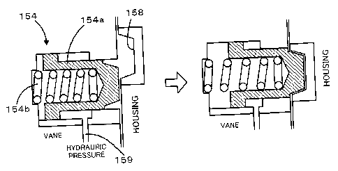
(00231 A lock pin 154 is set on the vane element 152b of the VVT
controller 152 to fix the relative rotation of the vane element
152b to the housing element 152a. The schematic structure of the
lock pin 154 is shown in Fig. 6. As illustrated, the lock pin 154
has a lock pin body 154a and a spring 154b arranged to press the
lock pin body 154a toward the housing element 152a. At the most
19
CA 02652099 2008-11-12
delayed angle of the intake camshaft 129, the lock pin body 154a
of the lock pin 154 is fit in a groove 158 formed in the housing
element 152a by the pressing force of the spring 154b, so that the
vane element 152b is fastened to the housing element 152a. A
non-illustrated hydraulic actuator is provided to utilize a supply
of oil from a non-illustrated oil pump and apply a hydraulic pressure
exceeding the pressing force of the spring 154b via an oil path
159. The applied hydraulic pressure enables the lock pin body 154a
of the lock pin 154 to be pulled out of the groove 158.
[0024] The engine 22 is under control of an engine electronic control
unit 24 (hereafter referred to as engine ECU 24) . The engine ECU
24 is constructed as a microprocessor including a CPU 24a, a ROM
24b that stores processing programs, a RAM 24c that temporarily
stores data, input and output ports (not shown) , and a communication
port (not shown). The engine ECU 24 receives, via its input port
(not shown), signals from various sensors that measure and detect
the conditions of the engine 22. The signals input into the engine
ECU 24 include a crank position from a crank position sensor 140
detected as the rotational position of the crankshaft 26, a cooling
water temperature from a water temperature sensor 142 measured as
the temperature of cooling water in the engine 22, an in-cylinder
pressure Pin from a pressure sensor 143 located inside the
combustion chamber, a cam position from a cam position sensor 144
detected as the rotational position of an exhaust camshaft 131b
driven to open and close an intake camshaft 129 of the intake valve
128 and an exhaust valve 131 for gas intake and exhaust into and
CA 02652099 2008-11-12
from the combustion chamber, a throttle valve position from a
throttle valve position sensor 146 detected as the opening or
position of the throttle valve 124, an air flow meter signal AF
from an air flow meter 148 attached to an air intake conduit, an
intake air temperature from a temperature sensor 149 attached to
the air intake conduit, an air-fuel ratio from an air fuel ratio
sensor 135a, and an oxygen signal from an oxygen sensor 135b. The
engine ECU 24 outputs, via its output port (not shown), diverse
control signals and driving signals to drive and control the engine
22, for example, driving signals to the fuel injection valve 126,
driving signals to a throttle valve motor 136 for regulating the
position of the throttle valve 124, control signals to an ignition
coil 138 integrated with an igniter, and control signals to a
variable valve timing mechanism 150 to vary the open and close
timings of the intake valve 128. The engine ECU 24 communicates
with the hybrid electronic control unit 70. The engine ECU 24
receives control signals from the hybrid electronic control unit
70 to drive and control the engine 22, while outputting data
regarding the driving conditions of the engine 22 to the hybrid
electronic control unit 70 according to the requirements.
[0025] The power distribution and integration mechanism 30 has a
sun gear 31 that is an external gear, a ring gear 32 that is an
internal gear and is arranged concentrically with the sun gear 31,
multiple pinion gears 33 that engage with the sun gear 31 and with
the ring gear 32, and a carrier 34 that holds the multiple pinion
gears 33 in such a manner as to allow free revolution thereof and
21
CA 02652099 2008-11-12
free rotation thereof on the respective axes. Namely the power
distribution and integration mechanism 30 is constructed as a
planetary gear mechanism that allows for differential motions of
the sun gear 31, the ring gear 32, and the carrier 34 as rotational
elements. The carrier 34, the sun gear 31, and the ring gear 32
in the power distribution and integration mechanism 30 are
respectively coupled with the crankshaft 26 of the engine 22, the
motor MGl, and the reduction gear 35 via ring gear shaft 32a. While
the motor MGl functions as a generator, the power output from the
engine 22 and input through the carrier 34 is distributed into the
sun gear 31 and the ring gear 32 according to the gear ratio. While
the motor MG1 functions as a motor, on the other hand, the power
output from the engine 22 and input through the carrier 34 is
combined with the power output from the motor MGl and input through
the sun gear 31 and the composite power is output to the ring gear
32. The power output to the ring gear 32 is thus finally transmitted
to the driving wheels 63a and 63b via the gear mechanism 60, and
the differential gear 62 from ring gear shaft 32a.
[0026] Both the motors MG1 and MG2 are known synchronous motor
generators that are driven as a generator and as a motor. The motors
MG1 and MG2 transmit electric power to and from a battery 50 via
inverters 41 and 42. Power lines 54 that connect the inverters 41
and 42 with the battery 50 are constructed as a positive electrode
bus line and a negative electrode bus line shared by the inverters
41 and 42. This arrangement enables the electric power generated
by one of the motors MG1 and MG2 to be consumed by the other motor.
22
CA 02652099 2008-11-12
The battery 50 is charged with a surplus of the electric power
generated by the motor MG1 or MG2 and is discharged to supplement
an insufficiency of the electric power. When the power balance is
attained between the motors MG1 and MG2, the battery 50 is neither
charged nor discharged. Operations of both the motors MGi and MG2
are controlled by a motor electronic control unit (hereafter
referred to as motor ECU) 40. The motor ECU 40 receives diverse
signals required for controlling the operations of the motors MG1
and MG2, for example, signals from rotational position detection
sensors 43 and 44 that detect the rotational positions of rotors
in the motors MG1 and MG2 and phase currents applied to the motors
MGi and MG2 and measured by current sensors (not shown) . The motor
ECU 40 outputs switching control signals to the inverters 41 and
42. The motor ECU 40 communicates with the hybrid electronic
control unit 70 to control operations of the motors MGi and MG2
in response to control signals transmitted from the hybrid
electronic control unit 70 while outputting data relating to the
operating conditions of the motors MGi and MG2 to the hybrid
electronic control unit 70 according to the requirements.
[0027] The battery 50 is under control of a battery electronic
control unit (hereafter referred to as battery ECU) 52. The battery
ECU 52 receives diverse signals required for control of the battery
50, for example, an inter-terminal voltage measured by a voltage
sensor (not shown) disposed between terminals of the battery 50,
a charge-discharge current measured by a current sensor (not shown)
attached to the power line 54 connected with the output terminal
23
CA 02652099 2008-11-12
of the battery 50, and a battery temperature Tb measured by a
temperature sensor 51 attached to the battery 50. The battery ECU
52 outputs data relating to the state of the battery 50 to the hybrid
electronic control unit 70 via communication according to the
requirements. The battery ECU 52 calculates a state of charge (SOC)
of the battery 50, based on the accumulated charge-discharge
current measured by the current sensor, for control of the battery
50.
[0028] The hybrid electronic control unit 70 is constructed as a
microprocessor including a CPU 72, a ROM 74 configured to store
processing programs, a RAM 76 configured to temporarily store data,
input and output ports (not shown), and a communication port (not
shown) . The hybrid electronic control unit 70 inputs, via its input
port, an ignition signal from an ignition switch 80, a gearshift
position SP or a current setting position of a gearshift lever 81
from a gearshift position sensor 82, an accelerator opening Acc
or the driver' s depression amount of the accelerator pedal 83 from
an accelerator pedal position sensor 84, a brake pedal position
BP or the driver's depression amount of the brake pedal 85 from
a brake pedal position sensor 86, and a vehicle speed V from a vehicle
speed sensor 88. As explained above, the hybrid electronic control
unit 70 is connected with the engine ECU 24, the motor ECU 40, and
the battery ECU 52 via the communication port to transmit various
control signals and data to and from the engine ECU 24, the motor
ECU 40, and the battery ECU 52. At least a parking position (P
position), a neutral position (N position), a drive position (D
24
CA 02652099 2008-11-12
position), and a reverse position (R position) are detectable as
the gearshift position SP of the gearshift lever 81 by the gearshift
position sensor 82.
[0029] The hybrid vehicle 20 of the embodiment thus constructed
calculates a torque demand to be output to the ring gear shaft 32a
functioning as the drive shaft, based on observed values of a vehicle
speed V and an accelerator opening Acc, which corresponds to a
driver's step-on amount of an accelerator pedal 83. The engine 22
and the motors MGi and MG2 are subjected to operation control to
output a required level of power corresponding to the calculated
torque demand to the ring gear shaft 32a. The operation control
of the engine 22 and the motors MGi and MG2 selectively effectuates
one of a torque conversion drive mode, a charge-discharge drive
mode, and a motor drive mode. The torque conversion drive mode
controls the operations of the engine 22 to output a quantity of
power equivalent to the required level of power, while driving and
controlling the motors MGi and MG2 to cause all the power output
from the engine 22 to be subjected to torque conversion by means
of the power distribution integration mechanism 30 and the motors
MGi and MG2 and output to the ring gear shaft 32a. The
charge-discharge drive mode controls the operations of the engine
22 to output a quantity of power equivalent to the sum of the required
level of power and a quantity of electric power consumed by charging
the battery 50 or supplied by discharging the battery 50, while
driving and controlling the motors MGi and MG2 to cause all or part
of the power output from the engine 22 equivalent to the required
CA 02652099 2008-11-12
level of power to be subjected to torque conversion by means of
the power distribution integration mechanism 30 and the motors MGl
and MG2 and output to the ring gear shaft 32a, simultaneously with
charge or discharge of the battery 50. The motor drive mode stops
the operations of the engine 22 and drives and controls the motor
MG2 to output a quantity of power equivalent to the required level
of power to the ring gear shaft 32a.
[0030] The description regards the operations of the hybrid vehicle
2 0 of the embodiment having the configuration described above. Fig.
7 is a flowchart showing a drive control routine executed by the
hybrid electronic control unit 70. This drive control routine is
performed repeatedly at preset time intervals (for example, at
every several msec).
[0031] At the start of the drive control routine, the CPU 72 of
the hybrid electronic control unit 70 inputs various data required
for control, for example, the accelerator opening Acc from the
accelerator pedal position sensor 84, the vehicle speed V from the
vehicle speed sensor 88, rotation speeds Nml and Nm2 of the motors
MGl and MG2, and a charge-discharge power demand Pb* to be charged
into or discharged from the battery 50 (step 5100). The rotation
speeds Nml and Nm2 of the motors MGl and MG2 are computed from the
rotational positions of the rotors in the motors MG1 and MG2 detected
by the rotational position detection sensors 43 and 44 and are input
from the motor ECU 40 by communication. The charge-discharge power
demand Pb* is set according to the state of charge (SOC) of the
battery 50 and is input from the battery ECU 52 by communication.
26
CA 02652099 2008-11-12
[0032] The CPU 72 subsequently identifies the status of the vehicle
as either in motion or at stop with a drive request (step S110).
The identification is based on the accelerator opening Acc, the
brake pedal position BP, and the vehicle speed V. The procedure
of the embodiment identifies the presence of a drive request when
a restart of the stopped vehicle is expected, for example, in
response to the driver's release of the brake pedal 85 at the drive
position of the gearshift lever 81 subsequent to the driver's
depression of the brake pedal 85 to stop the vehicle. Upon
identification of either the vehicle in motion or the vehicle at
stop with a drive request, the CPU 72 sets a torque demand Tr* to
be output to the ring gear shaft 32a or the driveshaft linked with
the drive wheels 63a and 63b as a torque required for the vehicle
and a power demand Pe* required for the vehicle, based on the input
accelerator opening Acc and the input vehicle speed V (step 5120) .
A concrete procedure of setting the torque demand Tr* in this
embodiment provides and stores in advance variations in torque
demand Tr* against the vehicle speed V with regard to various
settings of the accelerator opening Acc as a torque demand setting
map in the ROM 74 and reads the torque demand Tr* corresponding
to the given accelerator opening Acc and the given vehicle speed
V from this torque demand setting map. One example of the torque
demand setting map is shown in Fig. 8. The power demand Pe* is
obtained as the sum of the product of the set torque demand Tr*
and a rotation speed Nr of the ring gear shaft 32a and the
charge-discharge power demand Pb* to be charged into or discharged
27
CA 02652099 2008-11-12
from the battery 50. The rotation speed Nr of the ring gear shaft
32a may be given by multiplying the vehicle speed V by a conversion
factor k or by diving the rotation speed Nm2 of the motor MG2 by
a gear ratio Gr of the reduction gear 35. The procedure of the
embodiment does not take into account a potential loss in setting
the power demand Pe*, although the potential loss may be considered.
[0033] The power demand Pe* is compared with a preset reference
value Pref 1 (step 5130) . The reference value Pref 1 may be set to,
for example, a lower limit value of a power range enabling efficient
operation of the engine 22. The comparison between the power demand
Pe* and the reference value Prefl at step S130 determines whether
there is an operation demand of the engine 22. The power demand
Pe* of not less than the reference value Pref 1 suggests an operation
demand of the engine 22. In the operation stop condition of the
engine 22, the motor MGl is controlled to motor and start the engine
22 (steps 5140 and S150). The CPU 72 subsequently sets a target
rotation speed Ne* and a target torque Te* of the engine 22 according
to the power demand Pe* (step S160) and sets a target timing VT*
of the intake valve 128 based on the set target rotation speed Ne*
(step S170). The target rotation speed Ne* and the target torque
Te* of the engine 22 are set according to an efficient operation
curve of ensuring efficient operation of the engine 22 and a constant
power demand Pe* curve. Fig. 9 shows a process of setting the target
rotation speed Ne* and the target torque Te* with referring to an
operation curve of the engine 22 in operation demand of the engine
22 for driving (hereafter referred to as ' in operation demand for
28
CA 02652099 2008-11-12
driving'). As illustrated, the operation curve of the engine 22
in operation demand for driving is set in a range of the rotation
speed Ne that is not lower than a minimum rotation speed Neminl.
The target rotation speed Ne* and the target torque Te* are specified
as an intersection of this operation curve and a constant power
demand Pe* curve (= Ne*xTe*) . The minimum rotation speed Neminl
is determined according to the properties and the characteristics
of the engine 22 and may be set equal to, for example, 1000 rpm
or 1100 rpm. A concrete procedure of setting the target timing VT*
in this embodiment provides and stores in advance a variation in
target timing VT* against the target rotation speed Ne* of the engine
22 as a target timing setting map in operation demand for driving
and reads the target timing VT* corresponding to the given target
rotation speed Ne* from the map. One example of the target timing
setting map in operation demand for driving is shown in Fig. 10.
In the illustrated example of Fig. 10, the target timing VT* in
operation demand for driving is set to a predetermined timing
(reference timing) VT1 in a range of the target rotation speed Ne*
of the engine 22 of lower than a preset rotation speed Ni, which
is lower than the minimum rotation speed Neminl. The target timing
VT* in operation demand for driving is set to a predetermined timing
VT2, which is more advanced than the reference timing VT1, in a
range of the target rotation speed Ne* of the engine 22 of not lower
than a preset rotation speed N2, which is between the preset rotation
speed Ni and the minimum rotation speed Neminl. In a range of the
target rotation speed Ne* of the engine 22 of not lower than the
29
CA 02652099 2008-11-12
preset rotation speed Ni but lower than the preset rotation speed
N2, the target timing VT* in operation demand for driving is rather
abruptly varied to be advanced from the predetermined timing VT1
to the predetermined timing VT2 with an increase in target rotation
speed Ne*. As explained above, the predetermined timing VT1
represents the open-close timing of the intake valve 128
corresponding to the most delayed angle (reference angle) of the
intake camshaft 129. The predetermined timing VT2 represents the
open-close timing of the intake valve 128 corresponding to the
efficient angle of the intake camshaft 129. Here it is assumed that
the engine 22 is started for driving. In the structure of the
embodiment, the open-close timing of the intake valve 128 is set
to the most delayed angle at the stop of the operation of the engine
22. The lock pin 154 fixes the angle of the intake camshaft 129
to the most delayed angle (reference angle) . This means that the
open-close timing of the intake valve 128 is fixed to the
predetermined timing (reference timing) VT1. At a subsequent start
of the engine 22 to be driven at a relatively low rotation speed,
the open-close timing of the intake valve 128 may not be changed
from the predetermined timing VTl, due to the failed supply of oil
required for pulling the lock pin body 154a out of the groove 158
via the oil path 159. In this embodiment, the rotation speed Ni
is set to a value approximate to an upper limit value of a specific
rotation speed range of the engine 22 that does not allow the
open-close timing of the intake valve 128 to be changed from the
predetermined timing VT1, and may be set equal to, for example,
CA 02652099 2008-11-12
800 rpm or 850 rpm. The rotation speed N2 is set to a value
approximate to a lower limit value of a specific rotation speed
range of the engine 22 that enables the lock pin body 154a to be
pulled out of the groove 158 and ensures a sufficient oil supply
to the advance chamber of the VVT controller 152 via the oil control
valve 156. Namely the rotation speed N2 is set to a value
approximate to a lower limit value of a specific rotation speed
range of the engine 22 that allows the open-close timing of the
intake valve 128 to be sufficiently changed from the predetermined
timing VT1, and may be set equal to, for example, 900 rpm or 950
rpm. In operation demand for driving, a rotation speed of not lower
than the minimum rotation speed Neminl is set to the target rotation
speed Ne* of the engine 22, so that the predetermined timing VT2
is set to the target timing VT*.
[0034] The CPU 72 calculates a target rotation speed Nml* of the
motor MG1 from the set target rotation speed Ne* of the engine 22,
the rotation speed Nr (= Nm2/Gr) of the ring gear shaft 32a, and
a gear ratio p of the power distribution integration mechanism 30
according to Equation (1) given below, while calculating a torque
command Tml* of the motor MG1 from the calculated target rotation
speed Nml* and the current rotation speed Nml of the motor MG1
according to Equation (2) given below (step 5180) . The CPU 72 then
calculates a torque command Tm2* of the motor MG2 from the torque
demand Tr*, the torque command Tml* of the motor MG1, the gear ratio
p of the power distribution integration mechanism 30, and the gear
ratio Gr of the reduction gear 35 according to Equation (3) given
31
CA 02652099 2008-11-12
below (step S190) . Equation (1) is a dynamic relational expression
of the rotational elements included in the power distribution
integration mechanism 30. Fig. 11 is an alignment chart showing
torque-rotation speed dynamics of the respective rotational
elements included in the power distribution integration mechanism
30. A left S-axis represents a rotation speed of the sun gear 31
that is equivalent to the rotation speed Nml of the motor MGi. A
middle C-axis represents a rotation speed of the carrier 34 that
is equivalent to the rotation speed Ne of the engine 22. A right
R-axis represents the rotation speed Nr of the ring gear 32 obtained
by dividing the rotation speed Nm2 of the motor MG2 by the gear
ratio Gr of the reduction gear 35. Two thick arrows on the R-axis
respectively show a torque applied to the ring gear shaft 32a by
output of the torque Tml from the motor MGi, and a torque applied
to the ring gear shaft 32a via the reduction gear 35 by output of
the torque Tm2 from the motor MG2. Equations (1) and (3) are readily
introduced from this alignment chart of Fig. 11. Equation (2) is
a relational expression of feedback control to drive and rotate
the motor MGi at the target rotation speed Nml*. In Equation (2),
a coefficient 'k1' in a second term and a coefficient 'k2' in a
third term on the right side respectively denote a gain of a
proportional and a gain of an integral term.
Nml* = Ne*= (l+p) /p - Nm2/ (Gr=p) (1)
Tml* = PreviousTml* + ki(Nml*-Nml) + k21(Nml*-Nml)dt (2)
Tm2* = (Tr* + Tml*/p) / Gr (3)
[0035] After setting the target rotation speed Ne* and the target
32
CA 02652099 2008-11-12
torque Te* of the engine 22, the target timing VT*, and the torque
commands Tml* and Tm2* of the motors MG1 and MG2, the CPU 72 sends
the settings of the target rotation speed Ne* and the target torque
Te* of the engine 22 and the target timing VT* to the engine ECU
24 and the settings of the torque commands Tml* and Tm2* of the
motors MG1 and MG2 to the motor ECU 40 (step S200) and terminates
the drive control routine. In response to reception of the settings
of the target rotation speed Ne*, the target torque Te*, and the
target timing VT*, the engine ECU 24 performs required controls
including fuel injection control and ignition control of the engine
22 to drive the engine 22 at a specific drive point defined by the
target rotation speed Ne* and the target torque Te*, while
controlling the variable valve timing mechanism 150 to make the
open-close timing of the intake value 128 approach to the target
timing VT*. The motor ECU 40 receives the settings of the torque
commands Tml* and Tm2* and performs switching control of switching
elements included in the respective inverters 41 and 42 to drive
the motor MGl with the torque command Tml* and the motor MG2 with
the torque command Tm2*. In this state, the engine 22 is driven
at the rotation speed of not lower than the minimum rotation speed
Neminl with an open-close operation of the intake valve 128 at the
predetermined timing VT2. Such control ensures efficient
operation of the engine 22.
[0036] The power demand Pe* of less than the reference value Pref 1
at step S130 suggests no operation demand of the engine 22. The
CPU 72 then sets both the target rotation speed Ne* and the target
33
CA 02652099 2008-11-12
torque Te* of the engine 22 to 0 to stop the operation of the engine
22 (step S210), sets the torque command Tml* of the motor MGl to
0 (step S220), and divides the torque demand Tr* by the gear ratio
Gr of the reduction gear 35 to set the torque command Tm2* of the
motor MG2 (step S230) . The CPU 72 sends the settings of the target
rotation speed Ne* and the target torque Te* of the engine 22 to
the engine ECU 24 and the settings of the torque commands Tml* and
Tm2* of the motors MGl and MG2 to the motor ECU 40 (step S240) and
terminates the drive control routine. In response to reception of
the target rotation speed Ne* and the target torque Te* set equal
to 0, the engine ECU 24 keeps the stopped engine 22 in its operation
stop state, while stopping the operation of the driven engine 22.
[0037] Upon identification of neither the vehicle in motion nor
the vehicle at stop with a drive request at step 5110, it is
determined that the vehicle is at stop with no drive request. The
CPU 72 then sets the power demand Pe* to the charge-discharge power
demand Pb* to be charged into or discharged from the battery 50
(step S250) and compares the set power demand Pe* with a preset
reference value Pref2 (step S260) . The reference value Pref2 is
set to identify a charge demand of the battery 50 and is determined
according to the properties and the characteristics of the engine
22 to be smaller than the reference value Pref 1. The comparison
between the power demand Pe* and the reference value Pref 2 at step
S260 determines whether there is an operation demand of the engine
22 based on a charge demand for the battery 50. The comparison of
step S260 may use the state of charge (SOC) of the battery 50 or
34
CA 02652099 2008-11-12
another suitable f actor, instead of the power demand Pe*. The power
demand Pe* of not less than the reference value Pref2 suggests an
operation demand of the engine 22 based on a charge demand for the
battery 50. In the operation stop condition of the engine 22, the
motor MGl is controlled to motor and start the engine 22 (steps
S270 and S280). The CPU 72 subsequently sets the target rotation
speed Ne* and the target torque Te* of the engine 22 according to
the power demand Pe* (step S290) and sets the target timing VT*
of the intake valve 128 based on the set target rotation speed Ne*
(step S300). The target rotation speed Ne* and the target torque
Te* of the engine 22 are set according to an operation curve of
the engine 22 in operation demand of the engine 22 in the vehicle
stop state without a drive request (hereafter referred to as 'in
vehicle stop-state operation demand') and a constant power demand
Pe* curve. Fig. 12 shows a process of setting the target rotation
speed Ne* and the target torque Te* with referring to an operation
curve of the engine 22 in vehicle stop-state operation demand. For
the purpose of reference, the operation curve in operation demand
for driving is shown as a one-dot chain line curve in Fig. 12. As
illustrated, the operation curve of the engine 22 in vehicle
stop-state operation demand is set in a range of the rotation speed
Ne of not lower than a minimum rotation speed Nemin2, which is lower
than the minimum rotation speed Neminl. The target rotation speed
Ne* and the target torque Te* are specified as an intersection of
this operation curve and a constant power demand Pe* curve (=
Ne*xTe*). The minimum rotation speed Nemin2 is determined
CA 02652099 2008-11-12
according to the properties and the characteristics of the engine
22 and may be set equal to, for example, 700 rpm or 750 rpm. In
this state, there is an operation demand of the engine 22 based
on a charge demand of the battery 50. The power demand Pe* is
generally not a significantly large value with the setting of the
charge-discharge power demand Pb*. The target rotation speed Ne*
of the engine 22 is thus expected to be equal to or slightly higher
than the minimum rotation speed Nemin2. A concrete procedure of
setting the target timing VT* in this embodiment provides and stores
in advance a variation in target timing VT* against the target
rotation speed Ne* of the engine 22 as a target timing setting map
in vehicle stop-state operation demand and reads the target timing
VT* corresponding to the given target rotation speed Ne* from the
map. One example of the target timing setting map in vehicle
stop-state operation demand is shown in Fig. 13. For the purpose
of reference, the variation in target timing VT* in operation demand
for driving is shown by the one-dot chain line. In the illustrated
example of Fig. 13, the target timing VT* in vehicle stop-state
operation demand is set to the predetermined timing (reference
timing) VT1 in a range of the target rotation speed Ne* of the engine
22 of lower than the preset rotation speed Ni, which is higher than
the minimum rotation speed Nemin2. In a range of the target
rotation speed Ne* of not lower than the preset rotation speed N1,
the target timing VT* in vehicle stop-state operation demand is
smoothly and moderately varied to be advanced from the
predetermined timing VT1 to a predetermined timing VT3, which is
36
CA 02652099 2008-11-12
between the predetermined timing VT1 and the predetermined timing
VT2, with an increase in target rotation speed Ne*, compared with
the target timing VT* in operation demand for driving. As mentioned
above, in vehicle stop-state operation demand, the target rotation
speed Ne* of the engine 22 is set equal to or slightly higher than
the minimum rotation speed Nemin2. The target timing VT* in vehicle
stop-state operation demand is set to have a smaller degree of
advance from the predetermined timing (reference timing) VT1 and
to be a more delayed timing, compared with the target timing VT*
in operation demand for driving. Since the target rotation speed
Ne* of the engine 22 is set equal to or slightly higher than the
minimum rotation speed Nemin2, the predetermined timing VT3 may
represent an identical open-close timing with or a slightly delayed
open-close timing than the predetermined timing VT2.
[00381 The CPU 72 calculates the torque command Tml* of the motor
MG1 in the same manner as step S180 explained above (step S310)
and sets the torque command Tm2* of the motor MG2 to 0 (step S320) .
The CPU 72 then sends the settings of the target rotation speed
Ne* and the target torque Te* of the engine 22 and the target timing
VT* to the engine ECU 24 and the settings of the torque commands
Tml* and Tm2* of the motors MG1 and MG2 to the motor ECU 40 (step
S330) and terminates the drive control routine. In this state, the
motor MG1 uses the output power of the engine 22 to generate electric
power, which is charged into the battery 50.
[00391 Here it is assumed that the operation of the engine 22 is
started in response to a charge demand of the battery 50 in the
37
CA 02652099 2008-11-12
vehicle stop state. In the structure of the embodiment, the engine
22 is driven at a rotation speed of not lower than the relatively
low minimum rotation speed Nemin2. Such drive control effectively
reduces the driver's uncomfortable feeling or odd feeling triggered
by operation of the engine 22 at a high rotation speed, compared
with the control of driving the engine 22 at a rotation speed of
not lower than the relatively high minimum rotation speed Neminl.
At the open-close timing of the intake valve 128 set to the
predetermined timing (reference timing) VT1, when the engine 22
is started to be driven at the rotation speed of not lower than
the minimum rotation speed Nemin2, there may be an insufficient
supply of oil required for changing the open-close timing of the
intake valve 128 in some condition of the rotation speed Ne of the
engine 22. The insufficient oil supply may not allow the open-close
timing of the intake valve 128 to be changed from the predetermined
timing VT1. The drive control of the embodiment opens and closes
the intake valve 128 at the target timing VT* corresponding to the
target rotation speed Ne* in vehicle stop-state operation demand.
Compared with the open-close operation of the intake valve 128 at
the target timing VT* fixed to the predetermined timing VT2 whether
in operation demand for driving or in vehicle stop-state operation
demand, the drive control of the embodiment ensures the better
open-close timing of the intake valve 128 according to the operating
condition of the engine 22 and the more appropriate control of the
variable valve timing mechanism 150. The target timing VT* is set
to smoothly and moderately advance the open-close timing of the
38
CA 02652099 2008-11-12
intake valve 128 with an increase in target rotation speed Ne* of
the engine 22. Such drive control effectively prevents an abrupt
change of the target timing VT* against a variation in target
rotation speed Ne*.
[0040] In response to determination of no charge demand for the
battery 50 at step S260, it is determined that there is no operation
demand of the engine 22. The CPU 72 accordingly sets both the target
rotation speed Ne* and the target torque Te* of the engine 22 to
0 to stop the operation of the engine 22 (step S340) and sets the
torque command Tml* of the motor MGl and the torque command Tm2*
of the motor MG2 to 0 (step S350) . The CPU 72 sends the settings
of the target rotation speed Ne* and the target torque Te* of the
engine 22 to the engine ECU 24 and the settings of the torque commands
Tml* and Tm2* of the motors MGl and MG2 to the motor ECU 40 (step
S360) and terminates the drive control routine.
[0041] As described above, in vehicle stop-state operation demand
to give an operation demand of the engine 22 based on a charge demand
of the battery 50 in the vehicle stop state without a drive request,
the hybrid vehicle 20 of the embodiment drives the engine 22 at
the rotation speed of not lower than the relatively low minimum
rotation speed Nemin2. Such drive control effectively reduces the
driver's uncomfortable feeling or odd feeling triggered by
operation of the engine 22 at a high rotation speed. In operation
demand for driving to give an operation demand of the engine 22
for driving, the hybrid vehicle 20 of the embodiment opens and closes
the intake valve 128 at the predetermined timing VT2. In vehicle
39
CA 02652099 2008-11-12
stop-state operation demand, the hybrid vehicle 20 of the
embodiment opens and closes the intake valve 128 at a more delayed
open-close timing having a smaller degree of advance from the
predetermined timing (reference timing) VT1 than the open-close
timing in operation demand for driving. Compared with the
open-close operation of the intake valve 128 at the fixed timing
VT2 whether in operation demand for driving or in vehicle stop-state
operation demand, the drive control of the embodiment ensures the
better open-close timing of the intake valve 128 according to the
operating condition of the engine 22 and the more appropriate
control of the variable valve timing mechanism 150. In vehicle
stop-state operation demand, the open-close timing of the intake
valve 128 is smoothly and moderately advanced with an increase in
target rotation speed Ne* of the engine 22. Such drive control
effectively prevents an abrupt change of the open-close timing of
the intake valve 128 against a variation in target rotation speed
Ne*.
[00421 The above description regards drive control of the hybrid
vehicle 20 of the embodiment in the case of the vehicle in motion
or at stop with a drive request and in the case of the vehicle at
stop without a drive request. In response to an operation demand
of the engine 22 in the case of the vehicle at stop with a drive
request, a smoothing operation or a rating operation may be
performed to gradually vary the target rotation speed Ne* and the
target torque Te* of the engine 22 and the target timing VT* in
the transition from the operation curve of the engine 22 in vehicle
CA 02652099 2008-11-12
stop-state operation demand shown in Fig. 12 and the target timing
VT* in vehicle stop-state operation demand shown in Fig. 13 to the
operation curve of the engine 22 in operation demand for driving
shown in Fig. 9 and the target timing VT* in operation demand for
driving shown in Fig. 10. The smoothing operation or the rating
operation desirably prevents an abrupt change of the target
rotation speed Ne* and the target torque Te* of the engine 22 and
the target timing VT*.
[0043] In the case of the vehicle at stop without a drive request,
the hybrid vehicle 20 of the embodiment identifies an operation
demand of the engine 22 based on a charge demand for the battery
50. The operation demand of the engine 22 may be based on not only
the charge demand for the battery 50 but another demand, for example,
a warm-up demand. In the case of idling the engine 22 based on a
warm-up demand, the operation of the engine 22 at the relatively
low minimum rotation speed Nemin2 effectively reduces the driver's
uncomfortable feeling or odd feeling triggered by operation of the
engine 22 at a relatively high rotation speed.
[0044] In vehicle stop-state operation demand, the hybrid vehicle
20 of the embodiment operates the engine 22 at the rotation speed
of not lower than the minimum rotation speed Nemin2, which is lower
than the preset rotation speed N1 and the preset rotation speed
N2. The minimum rotation speed Nemin2 may be set to a rotation speed
approximate to the preset rotation speed N1, as long as the minimum
rotation speed Nemin2 is lower than the minimum rotation speed
Nemini in operation demand for driving. Such modified drive
41
CA 02652099 2008-11-12
control also effectively reduces the driver's uncomfortable
feeling or odd feeling triggered by operation of the engine 22 at
a relatively high rotation speed, compared with the operation of
the engine 22 at the rotation speed of not lower than the minimum
rotation speed Neminl in operation demand for driving.
[0045] As shown in the target timing setting maps of Figs. 10 and
13, the hybrid vehicle 20 of the embodiment sets the target timing
VT* based on the target rotation speed Ne* of the engine 22. The
target timing VT* may alternatively be set based on the rotation
speed Ne of the engine 22, instead of the target rotation speed
Ne*. The rotation speed Ne of the engine 22 may be computed from
a signal of a crank position sensor (not shown) attached to the
crankshaft 26 and is input from the engine ECU 24 by communication.
[0046] The hybrid vehicle 20 of the embodiment stores the two
operation curves, that is, the operation curve in operation demand
for driving and the operation curve in vehicle stop-state operation
demand. The number of the operation curves applied is, however,
not restricted to two. Three or any greater number of operation
curves may be stored and used, instead of the two operation curves.
For example, multiple operation curves according to the torque
demand Tr* may be provided and stored as the operation curve in
operation demand for driving. The hybrid vehicle 20 of the
embodiment sets the target rotation speed Ne* and the target torque
Te* according to the power demand Pe* and the operation curve. The
target rotation speed Ne* and the target torque Te* may, however,
be set according to only the power demand Pe* without using the
42
CA 02652099 2008-11-12
operation curve.
[0047] In vehicle stop-state operation demand, the hybrid vehicle
20 of the embodiment sets the target timing VT* to be linearly
advanced from the predetermined timing VT1 to the predetermined
timing VT3 with an increase in target rotation speed Ne* in the
range of the target rotation speed Ne* of not lower than the preset
rotation speed Nl, as shown in the target timing setting map in
vehicle stop-state operation demand of Fig. 13. As shown in one
modified target timing setting map in vehicle stop-state operation
demand of Fig. 14, the target timing VT* may be set to be advanced
stepwise. In operation demand for driving, the target timing VT*
may be set to be advanced stepwise in the range of the target rotation
speed Ne* of not lower than the preset rotation speed Ni but lower
than the preset rotation speed N2. The engine 22 in operation
demand for driving is, however, driven at the rotation speed of
not lower than the minimum rotation speed Nemini, which is higher
than the preset rotation speed N2, as described previously. The
target timing VT* is accordingly fixed to the predetermined timing
VT2 as explained above in the embodiment.
[0048] The hybrid vehicle 20 of the embodiment has the lock pin
154 designed to fix the open-close timing of the intake valve 128
at the most delayed angle of the intake camshaft 129 and to cancel
the fixed open-close timing of the intake valve 128 by means of
the oil supply with rotation of the engine 22. The lock pin 154
is, however, not essential but may be omitted. In a modified
structure without the lock pin 154, the predetermined timing
43
CA 02652099 2008-11-12
(reference timing) VT1 may be a specific open-close timing of the
intake valve 128 that does not allow application of hydraulic
pressure to either of the advance chamber and the delay chamber
of the VVT controller 152.
[00491 The hybrid vehicle 20 of the embodiment is equipped with
the variable valve timing mechanism 150 designed to change only
the open-close timing of the intake valve 128. The variable valve
timing mechanism 150 may be replaced by a variable valve timing
mechanism designed to change only the open-close timing of the
exhaust valve 131 or a variable valve timing mechanism designed
to change both the open-close timing of the intake valve 128 and
the open-close timing of the exhaust valve 131. In application of
the variable valve timing mechanism of the modified structure to
change only the open-close timing of the exhaust valve 131, a lock
pin may be provided to fix the open-close timing of the exhaust
valve 131 at a most advanced angle of the exhaust camshaft 131b
and cancel the fixed open-close timing of the exhaust valve 131
by means of oil supply with rotation of the engine 22. In this
modified application, a reference timing is set to a specific
open-close timing of the exhaust valve 131 corresponding to the
most advanced angle of the exhaust camshaft 13lb. In vehicle
stop-state operation demand, the exhaust valve 131 is opened and
closed at a more advanced open-close timing to have a smaller degree
of delay from the reference timing than the open-close timing in
operation demand for driving. The modified drive control ensures
the better open-close timing of the exhaust valve 131 according
44
CA 02652099 2008-11-12
to the operating condition of the engine 22 and the more appropriate
control of the variable valve timing mechanism 150 as in the
embodiment discussed above.
[0050] In the hybrid vehicle 20 of the embodiment, the power of
the motor MG2 is subjected to gear change by the reduction gear
35 and is output to the ring gear shaft 32a. In one possible
modification shown as a hybrid vehicle 120 of Fig. 15, the power
of the motor MG2 may be output to another axle (that is, an axle
linked with wheels 64a and 64b), which is different from an axle
connected with the ring gear shaft 32a (that is, an axle linked
with the wheels 63a and 63b).
[0051] In the hybrid vehicle 20 of the embodiment, the power of
the engine 22 is output via the power distribution integration
mechanism 30 to the ring gear shaft 32a functioning as the drive
shaft linked with the drive wheels 63a and 63b. In another possible
modification of Fig. 16, a hybrid vehicle 220 may have a pair-rotor
motor 230, which has an inner rotor 232 connected with the crankshaft
26 of the engine 22 and an outer rotor 234 connected with the drive
shaft for outputting the power to the drive wheels 63a, 63b and
transmits part of the power output from the engine 22 to the drive
shaft while converting the residual part of the power into electric
power.
[0052] The embodiment regards the hybrid vehicle driven with the
output power of the engine and the output power of the motor. The
technique of the invention is, however, not restricted to the hybrid
vehicle of this conf iguration but is applicable to any motor vehicle
CA 02652099 2008-11-12
equipped with an internal combustion engine configured to output
a power for driving the vehicle and to be drivable at any arbitrary
drive point irrespective of a driving condition and with an
open-close timing change mechanism configured to change the
open-close timing of at least one of an intake valve and an exhaust
valve of the internal combustion engine by utilizing a supply of
an operating fluid with rotation of an output shaft of the internal
combustion engine. The technique of the invention is not
restricted to such hybrid vehicles or motor vehicles but is also
actualized by any of other various vehicles and a control method
of such a vehicle.
[0053] The embodiment discussed above is to be considered in all
aspects as illustrative and not restrictive. There may be many
modifications, changes, and alterations without departing from the
scope or spirit of the main characteristics of the present invention.
The scope and spirit of the present invention are indicated by the
appended claims, rather than by the foregoing description.
Industrial Applicability
[0054] The technique of the present invention is preferably applied
to the manufacturing industries of vehicles.
46