Note: Descriptions are shown in the official language in which they were submitted.
~.....a. ~.~. . ~, . ,... o <~~~
CA 02652182 2009-02-02
MODULAR C02 REFRIGERATION SYSTEM
FIELD
100011 The present invention relates to a refrigeration system with a low
temperature
portion and a medium temperature portion. The present invention relates more
particularly to a refrigeration system where the low temperature portion may
receive
condenser cooling from refrigerant in the medium temperature portion in a
cascade
arrangement, or may share condenser cooling directly with the medium
temperature
system. The present invention relates more particularly to use of carbon
dioxide (C02)
as both a low temperature refrigerant and a medium temperature coolant.
BACKGROUND
[0002] Refrigeration systems typically include a refrigerant that circulates
through a
series of components in a closed system to maintain a cold region (e.g., a
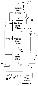
region with a
temperature below the temperature of the surroundings). One exemplary
refrigeration
system is a vapor refrigeration system including a compressor. Such a
refrigeration
system may be used, for example, to maintain a desired temperature within a
temperature
controlled storage device, such as a refrigerated display case, coolers,
freezers, etc. The
refrigeration systems may have a first portion with equipment intended to
maintain a first
temperature (such as a low temperature) and a second temperature (such as a
medium
temperature). The refrigerant in the low temperature portion and the
refrigerant in the
medium temperature portion are condensed in condensers which require a source
of a
coolant.
-1-
CA 02652182 2009-02-02
[0003] Different refrigerants maybe be used in different vapor compression
refrigeration systems to maintain cases at several different temperatures.
However, using
different refrigerants typically requires separate closed loop systems and
additional
piping and equipment.
[0004] Further, with a traditional refrigeration system, if the amount of
space needing
for cooling is increased, for instance, by adding additional chilled display
cases,
equipment such as compressors may have to be replaced to accommodate the
additional
cooling load.
[0005] Accordingly, it would be desirable to provide a modular refrigeration
system
capable of using C02 as a refrigerant for cooling refrigeration devices
operating at
different temperatures.
SUMMARY
[0006] One embodiment of the invention relates to a cascade C02 refrigeration
system,
comprising a medium temperature loop for circulating a medium temperature
refrigerant
and a low temperature loop for circulating a C02 refrigerant. The medium
temperature
loop including a compressor; a discharge header; a condenser; a subcooler; an
expansion
device; and a heat exchanger having a first side and a second side. The first
side of the
heat exchanger is configured to evaporate the medium temperature refrigerant.
The
medium temperature loop further includes a suction header configured to direct
medium
temperature refrigerant to the compressor. The low temperature loop includes a
compressor, a discharge header configured to circulate the C02 refrigerant
through the
second side of the heat exchanger to condense the CO2 refrigerant; a liquid-
vapor
separator configured to collect liquid C02 refrigerant and to direct vapor C02
refrigerant
to the second side of the heat exchanger; a pump; a subcooler; a liquid C02
refrigerant
supply header; a plurality of medium temperature loads configured to receive
liquid C02
refrigerant from the liquid CO2 refrigerant supply header for use as a liquid
coolant in the
-2-
CA 02652182 2009-02-02
medium temperature loads; a plurality of low temperature loads; and a low
temperature
expansion device configured to expand the liquid C02 refrigerant from the
liquid C02
refrigerant supply header into liquid-vapor C02 for use as a refrigerant by
the low
temperature loads.
[0007] Another embodiment relates to a cascade refrigeration system having a
common
subcooled liquid supply for both low temperature refrigerated cases and medium
temperature refrigerated cases. The system includes an upper cascade portion
for
circulating a first refrigerant; lower cascade portion for circulating a
second refrigerant; a
plurality of medium temperature refrigerated cases configured to receive
liquid second
refrigerant from the common subcooled liquid supply for use as a coolant in
the medium
temperature refrigerated cases, and an expansion device configured to expand
the liquid
second refrigerant from the common subcooled liquid supply into liquid-vapor
second
refrigerant for use as a refrigerant by the low temperature refrigerated
cases. The upper
cascade portion includes a compressor, a condenser, an expansion device, and a
heat
exchanger having a first side and a second side, the first side configured to
evaporate the
first refrigerant. The lower cascade portion includes a compressor configured
to direct
the second refrigerant to the second side of the heat exchanger, the second
side of the
heat exchanger configured to condense the second refrigerant, a liquid-vapor
separator
configured to direct liquid second refrigerant to the common subcooled liquid
supply and
to direct vapor second refrigerant to the second side of the heat exchanger.
[0008] Yet another embodiment relates to a cascade refrigeration system having
a
common liquid supply for both low temperature refrigeration loads and medium
temperature refrigeration loads. The system includes an upper cascade portion
for
circulating a first refrigerant, a lower cascade portion for circulating a
second refrigerant,
and a liquid-vapor separator. The upper cascade portion including a
compressor, a
condenser, an expansion device, and a heat exchanger having a first side and a
second
side, the first side configured to evaporate the first refrigerant. The lower
cascade portion
including a compressor configured to direct the second refrigerant to the
second side of
-3-
.. . .. . . ---~,,... . _ ._ _. :. ... ....... ......a . . ..~............. ..
CA 02652182 2009-02-02
the heat exchanger, the second side of the heat exchanger configured to
condense the
second refrigerant. The liquid-vapor separator configured to receive the
liquid second
refrigerant from the second side of the heat exchanger and to provide a source
of liquid
second refrigerant for the common liquid supply. The medium temperature
refrigeration
loads are configured to receive liquid second refrigerant from the common
liquid supply
for use as a coolant. Expansion devices are configured to expand the liquid
second
refrigerant from the common liquid supply into a liquid-vapor mixture for use
as a second
refrigerant in the low temperature refrigeration loads.
[0009] Still another embodiment relates to a refrigeration system comprising a
plurality
of modular medium temperature compact chiller, a plurality of modular low
temperature
compact condenser units, a liquid-vapor separator communicating with the
modular low
temperature compact condenser units, and a pump. The modular medium
temperature
compact chiller units have a first heat exchanger and a second heat exchanger.
The
modular medium temperature compact chiller units are arranged in parallel and
configured to circulate a medium temperature refrigerant through the first and
second
heat exchangers to cool a medium temperature liquid coolant for circulation to
a plurality
of medium temperature refrigeration loads. The modular low temperature compact
condenser units have a first heat exchanger and a second heat exchanger. The
modular
low temperature compact condenser units are arranged in parallel, with the
first heat
exchanger configured to receive the medium temperature liquid coolant to
condense a
low temperature refrigerant for circulation to the first heat exchanger to
condense a vapor
C02 refrigerant to a liquid C02 refrigerant. The liquid-vapor separator
communicates
with the modular low temperature compact condenser units to direct vapor C02
refrigerant to the first heat exchanger and to receive liquid C02 refrigerant
from the first
heat exchanger. The pump is configured to direct the liquid C02 refrigerant
from the
liquid-vapor separator to a plurality of low temperature refrigeration loads.
-4-
CA 02652182 2009-02-02
BRIEF DESCRIPTION OF THE DRAWINGS
[0010] FIG. 1 is a block diagram of a modular cascade refrigeration system
according
to an exemplary embodiment using a C02 refrigerant.
[0011] FIG. 2 is a block diagram of a chiller unit for the refrigeration
system of FIG. 1
according to one exemplary embodiment.
[0012] FIG. 3 is a block diagram of a chiller unit for the refrigeration
system of FIG. 1
according to another exemplary embodiment.
[0013] FIG. 4 is a block diagram of one modular embodiment of the
refrigeration
system of FIG. 1.
[0014] FIG. 5 is a block diagram of a cascade refrigeration system according
to an
exemplary embodiment using a C02 refrigerant for both medium temperature cases
and
low temperature cases.
[0015] FIG. 6 is a block diagram of one modular embodiment of the
refrigeration
system of FIG. 5.
[0016] FIG. 7 is a block diagram of one modular embodiment of the
refrigeration
system of FIG. 5.
[0017] FIG. 8A is a block diagram of one modular embodiment of the
refrigeration
system of FIG. 5 including several pressure relief components.
[0018] FIG. 8B is a block diagram of a portion of the refrigeration system of
FIG. 8A
showing one exemplary configuration of several pressure release components.
[0019] FIG. 8C is a block diagram of a portion of the refrigeration system of
FIG. 8A
showing one exemplary configuration of several pressure release components.
-5-
CA 02652182 2009-02-02
[0020] FIG. 9 is a block diagram of a cascade refrigeration system according
to an
exemplary embodiment using a C02 refrigerant and having an external condensing
heat
exchanger.
DETAILED DESCRIPTION
[0021] Referring to FIG. 1, a refrigeration system 10 is shown according to an
exemplary embodiment. Refrigeration systems 10 typically include one or more
refrigerants (e.g., a vapor compression/expansion type refrigerant, etc.) that
circulate
through a series of components in a closed system to maintain a cold region
(e.g., a
region with a temperature below the temperature of the surroundings). The
refrigeration
system 10 of FIG. 1 is a cascade system that includes several subsystems or
loops.
According to an exemplary embodiment, the cascade refrigeration system 10,
comprises
a medium temperature loop 20 for circulating a medium temperature refrigerant
and a
low temperature loop 30 for circulating a low temperature C02 refrigerant.
[0022] The terms "low temperature" and "medium temperature" are used herein
for
convenience to differentiate between two subsystems of refrigeration system
10.
Medium temperature loop 20 maintains one or more cases 24 such as refrigerator
cases or
other cooled areas at a temperature lower than the ambient temperature but
higher than
low temperature cases 34. Low temperature loop 30 maintains one or more cases
34 such
as freezer display cases or other cooled areas at a temperature lower than the
medium
temperature. According to one exemplary embodiment, medium temperature cases
24
may be maintained at a temperature of approximately 20 F and low temperature
cases 34
may be maintained at a temperature of approximately minus (-) 20 F. Although
only
two subsystems are shown in the exemplary embodiments described herein,
according to
other exemplary refrigeration system 10 may include more subsystems that may
be
selectively cooled in a cascade arrangement or other cooling arrangement.
-6-
~ .. .. ~: ~.. .. ~ ~ . ~~~.s..~.
CA 02652182 2009-02-02
[0023] A first or medium temperature loop 20 (e.g., the upper cascade portion)
includes
a medium temperature chiller 22 (e.g. modular medium temperature compact
chiller
unit), one or more medium temperature cases 24 (e.g., refrigerated display
cases), and a
pump 26. Pump 26 circulates a medium temperature liquid coolant (e.g.,
propylene
glycol, water, etc.) between chiller 22 and cases 24 to maintain cases 24 at a
relatively
constant medium temperature. Medium temperature chiller 22 removes heat energy
from
medium temperature cases 24 and, in turn, gives the heat energy up to a heat
exchanger,
such as an outdoor fluid cooler 60 or outdoor cooling tower to be dissipated
to the
exterior or outside environment. Outdoor fluid cooler 60 cools a third coolant
(e.g.,
water, etc.) that is circulated with a pump 62.
[0024] Medium temperature chiller 22 is further coupled to a low-temperature
chiller
32 (e.g. modular low temperature compact condenser units) to absorb (e.g.
remove, etc.)
heat from a low temperature loop 30. The second or low temperature loop 30
(e.g., the
lower cascade portion) includes a low temperature chiller 32, one or more low
temperature cases 34 (e.g., refrigerated display cases, freezers, etc.), and a
pump 36.
Pump 36 circulates a low temperature coolant (e.g., carbon dioxide) between
chiller 32
and refrigerated cases 34 to maintain cases 34 at a relatively constant low
temperature.
The carbon dioxide (CO2) coolant is separated into liquid and gaseous portions
in a
receiver or liquid-vapor separator 38. Liquid C02 exits the liquid-vapor
separator 38 and
is pumped by pump 36 to valve 39 (which may be an expansion valve for
expanding
liquid CO2 into a low temperature saturated vapor for removing heat from low
temperature cases 34, and would be returned to the suction of a compressor,
such as
shown in FIGS. 5-7. According to another exemplary embodiment, C02 enters low
temperature cases 34 as a liquid coolant. After absorbing heat from low
temperature
cases 34, the C02 coolant returns to liquid-vapor separator 38 through a
return header.
Liquid-vapor separator 38 communicates with low temperature chiller 32 to
direct vapor
C02 refrigerant to chiller 32 and to receive liquid C02 refrigerant from
chiller 32.
-7-
CA 02652182 2009-02-02
Gaseous C02 is received by low temperature chiller 32, which in turn transfers
heat from
low temperature cases 34 to medium temperature chillers 22.
[0025] One exemplary chiller unit 40 is shown in FIG. 2 and may be either a
medium
temperature chiller 22 or a low temperature chiller 32. Chiller unit 40
includes a
refrigerant that is circulated through a vapor-compression refrigeration cycle
including a
first heat exchanger 42, a compressor 44, a second heat exchanger 46, and an
expansion
valve 48. In the first heat exchanger 42, the refrigerant absorbs heat from an
associated
load such as display case(s) or other cooled area via a coolant circulated by
a pump (e.g.
pump 36 for low temperature cases, pump 26 for medium temperature cases,
etc.). In the
second heat exchanger 46 (e.g. condenser, etc.), the refrigerant gives up heat
to a second
coolant. Various elements of the chiller unit 40 may be combined. For example,
heat
exchangers 42 and 46 may comprise a single device in one exemplary chiller
unit 40.
[0026] Another exemplary chiller unit 50 is shown in FIG. 3 and may be either
a low
temperature chiller 32 or a medium temperature chiller 22. Chiller unit 50 is
similar to
chiller unit 40 and also includes a refrigerant (e.g., a medium temperature
refrigerant or a
low temperature refrigerant) that is circulated through a vapor-compression
refrigeration
cycle including a first heat exchanger 52, a compressor 54, a second heat
exchanger 56,
and an expansion valve 58. Chiller unit further includes an intermediate heat
exchanger
61 (e.g., a subcooler) and a reservoir 62. In the first heat exchanger 52, the
refrigerant
absorbs heat from an associated display case(s) or other cooled area via a
coolant
circulated by a pump (e.g. pump 26 for low temperature cases, pump 36 for
medium
temperature cases, etc.). For example, if chiller 50 is a low temperature
chiller of system
10, liquid-vapor separator 38 directs vapor CO2 refrigerant to first heat
exchanger 52 and
receives liquid CO2 refrigerant from first heat exchanger 52. In the second
heat
exchanger 56 (e.g. condenser, etc.), the refrigerant gives up heat to a second
coolant.
Various elements of the chiller unit 50 may be combined. For example, heat
exchangers
52 and 56 may comprise a single device in one exemplary chiller unit 50.
-8-
CA 02652182 2009-02-02
[0027] Intermediate heat exchanger 61 allows refrigerant exiting second heat
exchanger
56 (e.g., as a saturated liquid) to be subcooled further by low temperature
refrigerant
exiting first heat exchanger 52. By subcooling the refrigerant with heat
exchanger 61, the
efficiency of the system is increased by reducing premature vaporization or
flash off of
the refrigerant before it reaches the heat exchanger 52. Further, the
subcooled refrigerant
is then expanded through expansion valve 58 at a lower enthalpy than it would
be if it
were not first subcooled. The lower enthalpy vapor refrigerant is then able to
absorb
more heat as it passes through first heat exchanger 52.
100281 According to one exemplary embodiment, chiller unit 40 is a compact
modular
chiller unit. System 10 may include a multitude of chiller units 40 or 50
arranged in
parallel as low temperature chillers (e.g. condensing units) 32 and medium
temperature
chillers 22. The number of chiller units 40 or 50 may be varied to accommodate
various
cooling loads associated with a particular system. Likewise, the number of
medium
temperature cases 24 and low temperature cases 34 may be varied. FIG. 4 shows
one
exemplary embodiment of a system 10 that is adapted to accommodate multiple
medium
temperature cooling loads such as medium temperature cases 24 and multiple low
temperature cooling loads such as low temperature cases 34 by providing
multiple low
temperature chillers 32 and multiple medium temperature chillers 22.
[0029] Referring now to FIG. 5, a refrigeration system 110 is shown according
to
another exemplary embodiment. Similar to system 10, system 110 typically
includes one
or more refrigerants (e.g., a vapor compression/expansion type refrigerant,
etc.) that
circulate through a series of components in a closed system to maintain a cold
region
(e.g., a region with a temperature below the temperature of the surroundings).
The
refrigeration system 110 of FIG. 5 is shown as a cascade system that includes
several
subsystems or loops. According to an exemplary embodiment the cascade
refrigeration
system 110 comprises a medium temperature loop 120 for circulating a medium
temperature refrigerant and a low temperature loop 130 for circulating a C02
refrigerant.
In contrast to system 10, both medium temperature cases 150 and low
temperature cases
-9-
~._. ~~ . ~...~ ~
CA 02652182 2009-02-02
140 are cooled by the C02 refrigerant of low temperature loop 130, using a
common
liquid C02 refrigerant supply header 138.
[0030] Low temperature loop 130 (e.g., lower cascade portion) includes a C02
refrigerant that is circulated through a refrigeration cycle including a
receiver or liquid-
vapor separator 132, a pump 134, a subcooler 136, a common liquid supply
header 138,
low temperature cases 140 with associated expansion devices 142, medium
temperature
cases 150 with associated control valves 152, and one or more compressors 146.
[0031] Liquid C02 refrigerant from liquid-vapor separator 132 is circulated by
pump
134 to supply header 138 through one side of subcooler 136. Pump 134
pressurizes the
C021iquid refrigerant. Subcooler 136 allows liquid C02 refrigerant exiting
separator
132 to be subcooled further by low temperature vapor C02 refrigerant exiting
low
temperature cases 140. By subcooling the refrigerant with pump 134 and
subcooler 136,
the efficiency of the system is increased by reducing premature vaporization
or flash off
of the refrigerant before it reaches the cooling loads. Further, the subcooled
refrigerant is
expanded through expansion valve 142 at a lower enthalpy than it would be if
it were not
first subcooled. The lower enthalpy liquid refrigerant is then able to absorb
more heat as
it passes through low temperature cases 140 and medium temperature cases 150.
[0032] Supply header 138 allows liquid C02 refrigerant to flow to both low
temperature cases 140 and medium temperature cases 150. Liquid refrigerant
flowing to
low temperature cases 140 passes through expansion devices 142 (e.g.,
expansion valves)
expanding to a liquid-vapor mixture. In this way, the C02 refrigerant is
provided as an
expansion type refrigerant at a relatively low temperature (e.g. approximately
minus (-)
20 F or other suitable "low" temperature) to cool the low temperature cases
140 (e.g.
cooling loads). Liquid refrigerant flowing to medium temperature cases 150, on
the other
hand, passes through valves 152 and is provided as a liquid refrigerant or
coolant at a
"medium" temperature (e.g. approximately 20 F or other suitable "medium"
temperature)
to cool the medium temperature cases 150 cooling loads. By using a common
supply
-10-
CA 02652182 2009-02-02
header 138, and passing the refrigerant using different components 142 and 152
before
they pass through low temperature cooling cases 140 and medium temperature
cooling
cases 150, the overall system 10 may be simplified by supplying a common
refrigerant
through a common header for use in refrigeration loads (e.g. display cases,
etc.) having
different operating temperature requirements. For instance, in a system with
interspersed
medium temperature cases 150 and low temperature cases 140 (such as shown in
FIG. 7),
a single supply header 138 eliminates the need to run two parallel lines to
service each
type of case.
[0033] After the C02 refrigerant has absorbed heat from low temperature cases
140, a
suction header 144 coupled to the low temperature cases 140 directs the C02
vapor
refrigerant through subcooler 136 and to compressor 146. The refrigerant is
superheated
in subcooler 136 by the warmer C02 liquid refrigerant from separator 132. By
superheating the C02 vapor refrigerant before it reaches compressor 146, the
chances of
any damaging moisture or liquids entering compressor 146 are reduced. The C02
vapor
refrigerant is compressed to a high-pressure super-heated vapor in compressor
146 and
directed to a heat exchanger 182 (e.g. de-superheater, etc.) shown as located
upstream of
heat exchanger 162 and intended to pre-cool the compressed C02 vapor prior to
entering
heat exchanger 162, in order to reduce the cooling demand or load required by
heat
exchanger 162. According to one embodiment, heat exchanger 182 is an air-
cooled heat
exchanger (operating in a manner similar to an air-cooled condenser) that
takes advantage
of available ambient air cooling to reduce the demand on medium temperature
loop 120.
According to an alternative embodiment, the de-superheating heat exchanger may
also be
arranged to selectively "reclaim" the heat from the compressed C02 vapor for
use in
other applications (e.g. heating water or air for other uses in a facility,
etc.) and as such
may be air or liquid cooled as appropriate. According to one exemplary
embodiment, the
temperature of the compressed vapor discharged from compressor(s) 146 is
within a
range of approximately 150-165 F, and the medium temperature cooling loop 120
is
required to reduce the temperature of the compressed vapor to about 25 F and
then
-11-
CA 02652182 2009-02-02
a
condense the C02 into liquid form. The applicants believe that use of the de-
superheater
as described would be effective in reducing the temperature of the compressed
vapor to
about 110 F (or lower depending on ambient conditions) prior to entering the
heat
exchanger 162, resulting in an energy savings of approximately 10% or more.
After
being cooled by the de-superheating heat exchanger 182, the C02 refrigerant is
directed
through valve 155 to heat exchanger 162 in the medium temperature loop. After
passing
through heat exchanger 162, the refrigerant returns to liquid-vapor separator
132.
[0034] Referring further to FIG. 5, the medium temperature case(s) 150 are
also shown
to receive liquid C02 as a coolant from common liquid supply header 138 and
through
valve(s) 152. After the C02 refrigerant has absorbed heat from medium
temperature
cases 150 the C02 refrigerant is typically in a combined liquid-vapor state. A
return
header 154 directs the C02 refrigerant back to separator 132. Each case 150
may have
an individual line that enters a common suction header rack. In separator 132,
the C02
liquid refrigerant is pumped back to low temperature loop 130 by pump 134,
while the
C02 vapor refrigerant is allowed to join C02 vapor refrigerant from compressor
146
through a return line 156, where it is cooled and condensed in heat exchanger
162 by
medium temperature loop 120.
[0035) The medium temperature loop 120 (e.g., the upper cascade portion) is
similar to
chiller unit 50 shown in FIG. 3 and includes a refrigerant (e.g. a medium
temperature
refrigerant) that is circulated through a vapor-compression refrigeration
cycle including a
first heat exchanger 162, a compressor 164, a second heat exchanger 166, and
an
expansion valve 168. Medium temperature loop 120 further includes an
intermediate
heat exchanger 170 (e.g. a subcooler) and a receiver tank 172. In the first
heat exchanger
162, the medium temperature refrigerant (on one side of the heat exchanger)
absorbs heat
from C02 vapor refrigerant (on the other side of the heat exchanger) received
from
compressor 146 and separator 132. The medium temperature refrigerant passes
through
subcooler 170 where it sub-cools the medium temperature refrigerant returning
from
second heat exchanger 166, which in turn, superheats the medium temperature
refrigerant
-12-
CA 02652182 2009-02-02
being routed from the first heat exchanger 162 to the compressor 164. By
superheating
the medium temperature refrigerant before it reaches compressor 164, the
chances of any
damaging moisture or liquids entering compressor 164 are reduced. The medium
temperature refrigerant is compressed to a super-heated vapor by compressor
164 before
being directed to second heat exchanger 166. Second heat exchanger 166 (e.g.
condenser, etc.) may transfer heat to the ambient air or may be a heat
exchanger that
gives up heat to an additional cooling loop, such as the outside fluid cooler
loop of
system 10. The medium temperature refrigerant is then directed to receiver
tank 172
before flowing to subcooler 170. After being cooled in subcooler 170, the
refrigerant is
expanded through expansion valve 168 before returning to first heat exchanger
162,
where it is used to condense the vapor C02 refrigerant.
[0036] Subcooler 170 allows refrigerant exiting second heat exchanger 166
(e.g., as a
saturated or subcooled liquid) to be subcooled further by low temperature
refrigerant
exiting first heat exchanger 162. By subcooling the medium temperature
refrigerant with
subcooler 170, the efficiency of the system is increased by reducing premature
vaporization or flash off of the refrigerant before it reaches the first heat
exchanger 162.
Further, the subcooled medium temperature refrigerant is then expanded through
expansion valve 168 at a lower enthalpy than it would be if it were not first
subcooled.
The lower enthalpy refrigerant is then able to absorb more heat as it passes
through first
heat exchanger 162.
[0037] One or more components of medium temperature loop 120 may be packaged
together as a modular chiller unit 122. According to one exemplary embodiment,
modular unit 122 includes first heat exchanger 162, compressor 164, second
heat
exchanger 166, and expansion valve 168 (in a manner similar to that shown in
Fig. 3),
and may also include a subcooler 170 (in a manner similar to that shown in
Fig. 4).
According to another embodiment, the modular unit 122 may also include
condenser 166
and receiver 172 as a packaged module, particularly when condenser 166 is
provided in
the form of a water-cooled heat exchanger. Modular chiller unit 122 allows
system 110
-13-
CA 02652182 2009-02-02
to be adapted to accommodate various numbers of medium temperature and low
temperature cooling loads. As shown according to several exemplary embodiments
in
FIGS. 6 and 7, a third cooling loop having an outdoor heat exchanger 160 and
pump 172
may be coupled to several modular units 122 to provide a cooling source for
the heat
removed from the C02 vapor refrigerant by modular units 122 of system 110.
Other
components of system 110 may also be provided in a modular manner to provide
additional cooling capacity. For example, multiple compressors 146 may be
provided
between subcooler 136 and modular units 122, and may be provided with other
components such as an oil separator 180. The modular nature of system 110
allows a
varied number of medium temperature cases 150 and low temperature cases 140 to
be
cooled. Medium temperature cases 150 and low temperature cases 140 may be
segregated as shown in FIG. 6 or may be mixed among each other as shown in
FIG. 7.
[0038] Referring now to FIGS. 8A-8C, refrigeration system 110 may further
include
several pressure relief mechanisms. For example, refrigeration system I 10 may
include
pressure limiting devices such as a first or low-side relief valve 196 and a
second or high-
side relief valve 198. Low-side valve 196 is provided on the low pressure side
of low
temperature loop 130 (e.g., the portion of low pressure loop 130 downstream
from
expansion devices 142 and on the suction side of compressors 146) to limit the
pressure
in low temperature loop 130. According to one exemplary embodiment, low-side
valve
196 is a relief valve that is configured to limit the low-side pressure in low
temperature
loop 130 to below a pressure of approximately 350 psig. High-side valve 198 is
provided
on the high pressure side of low temperature loop 130 (e.g., the portion of
low pressure
loop 130 downstream from compressors 146 and up to expansion devices 142) to
limit
the pressure in low temperature loop 130. According to one exemplary
embodiment,
high-side valve 198 is a relief valve that is configured to limit the high-
side pressure in
low temperature loop 130 to below approximately 550-600 psig.
-14-
. ~ ,... .~:. b . . . .=a~.~... ~.,...~ _ _ _ .M.~,._
CA 02652182 2009-02-02
[0039] Refrigeration system 110 may include a portion 190 (shown in more
detail in
FIGS. 8B and 8C) with solenoid valves 192 and check valves 194 that are
configured to
prevent pressure from rising above a predefined threshold in low temperature
loop 130.
A single solenoid valve 192 and check valve 194 may be provided on suction
header 144
(see FIG. 8B) or solenoid valves 192 and check valves 194 may be provided for
each
individual circuit between low temperature cases 140 and suction header 144
(see FIG.
8C). Solenoid valve 192 is provided in-line with suction header 144 or an
individual
circuit feeding suction header 144. Check valves 194 are provided on lines
connecting
the low pressure side of low temperature loop 130 (e.g. suction header 144) to
the high
pressure side of low temperature loop 130 (e.g., supply header 138). According
to
exemplary embodiments in FIGS. 8B and 8C, solenoid valves 192 are provided
upstream
of subcooler 136. According to other exemplary embodiments, solenoid valves
192 may
be provided downstream of subcooler 136 and upstream of compressors 146.
[0040] If the power for refrigeration system 110 is lost or otherwise
interrupted, the
cooling cycle keeping the C02 refrigerant cooled may be halted and the
temperature of
the C02 may rise, causing it to expand and threaten to damage components of
refrigeration system I 10, such as piping and components on low pressure side
of low
temperature loop 130 (e.g., suction header 144, individual circuits feeding
suction header
144, evaporators in low temperature cases 150, etc) upstream of solenoid
valves 192.
Upon loss of power, solenoid valves 192 are configured to close and isolate
compressors
146. When closed, solenoid valves 192 prevent possible damage to compressors
146 by
isolating them from C02 pressure built up in low temperature case 150
evaporators and
suction distribution piping.
[0041] Expansion devices 142 may be electronically controlled and configured
to close
automatically upon loss of power. However, some refrigerant may continue to
leak
through closed expansion devices 142 from the high-pressure side to the low
pressure
side of low temperature loop 130. If the pressure on the low pressure side of
low
temperature loop 130 exceeds the pressure on the high pressure side,
refrigerant may pass
-15-
CA 02652182 2009-02-02
through check valves 194 from the low pressure side to the high pressure side.
If the
pressure in the high pressure side exceeds a predetermined threshold, it
escapes (e.g.
vents, etc.) from refrigeration system 110 through high-side relief valve 198.
[0042] According to any exemplary embodiment, the pressure relief devices are
intended to minimize potential pressure related damage to the system in the
event of a
power loss. In the event that C02 refrigerant leaks-by (e.g. bleeds-past,
etc.) the
expansion valves 142, the C02 will remain in the evaporators of the low
temperature
loads (e.g. refrigerated cases or freezers, etc.) and will be cooled by the
thermal inertia of
the low temperature objects (e.g. food, etc.) stored therein. In this manner,
the pressure
of the C02 refrigerant in the refrigeration loads can go to a higher pressure
than the
pressure relief setting of relief valve 196, and bypass check valves 194 are
intended to
ensure that under any condition, the pressure of C02 refrigerant within the
refrigeration
loads does not exceed the pressure relief setpoint of the relief valve 198.
[0043) Referring to FIG. 9, condensing for the C02 refrigerant in the low
temperature
loop may be cooled by an outside ambient air-cooled heat exchanger, thus
minimizing or
eliminating the need for the upper cascade portion of the system, according to
another
embodiment. Under certain seasonal or climate temperature conditions, heat
exchanger
182 may act as an air-cooled condenser when the local ambient (e.g. outside)
air
temperature is sufficiently low (e.g. in cold climates, during winter months,
etc.). During
such cold ambient conditions, the ambient air temperature may be sufficiently
low (i.e.
below a predetermined ambient air temperature) that the C02 vapor refrigerant
exiting
compressor 146 may be substantially or completely condensed in heat exchanger
182.
The condensed (e.g. liquid) C02 refrigerant exiting heat exchanger 182 may
then be
routed through bypass line 157 directly to liquid-vapor separator 132, thus
reducing or
eliminating the need for operation of the medium temperature loop 120 and
gaining the
associated energy savings. A valve 159 (e.g. solenoid-operated valve, etc.) is
provided
on branch line 157 and is operable to open when the outside ambient air
temperature is
sufficiently low (i.e. below a predetermined temperature) that heat exchanger
182 can
-16-
~.,~ . ~, - ._ . ~ ...~ õ.~.. . .~.
CA 02652182 2009-02-02
condense the C02 vapor refrigerant exiting compressor 146. Valve 159 is also
operable
to close when the outside ambient air temperature rises and is no longer
sufficient to
condense the C02 vapor refrigerant. Valve 159 may be controlled using any
suitable
controller and control scheme. For example, temperature and/or pressure
sensing devices
(shown as a temperature sensor 149 and a pressure sensor 151) may be provided
on the
outlet of heat exchanger 182 to provide signals representative of the
temperature and
pressure of the C02 refrigerant exiting the heat exchanger. The signals
representative of
the C02 refrigerant temperature and pressure may be provided to a control
device (e.g.
having a microprocessor or other suitable device - shown as controller 153)
that
determines whether the C02 refrigerant exiting heat exchanger 182 is below the
saturation temperature for the C02 refrigerant. When controller 153 determines
that the
temperature of the C02 refrigerant is below its saturation temperature
(indicating that the
ambient air temperature is below the predetermined temperature and the C02
refrigerant
has condensed to a liquid state), then controller 153 may provide an output
signal to close
valve 155 and to open valve 159. In a similar manner, when controller 153
determines
that the temperature of the C02 refrigerant is at or above its saturation
temperature
(indicating that the ambient air temperature is above the predetermined
temperature and
the C02 refrigerant has not condensed to a liquid state), controller 153 may
provide a
signal to close valve 159 and open valve 155 to direct the cooled (but not yet
condensed)
C02 refrigerant to heat exchanger 162 of the medium temperature cooling loop
for
further cooling. Heat exchanger 182 is intended to permit the option of
converting the
source of cooling for the C02 refrigerant from the medium temperature cooling
loop 120
to an outside heat exchanger 182 to provide "free cooling" during periods when
the
outside ambient air temperature is sufficiently low.
-17-
. _ ~
CA 02652182 2009-02-02
[0044] While the refrigerant for low temperature loop 130 has been described
above as
C02, it should be realized that the arrangement of low temperature loop 130
allows
various refrigerants to be used in both a liquid state and a vapor state to
cool medium
temperature cases 150 and low temperature cases 140. For example, according to
anther
exemplary embodiment, the low temperature refrigerant may be propane, ammonia
or
any other suitable refrigerant.
[0045] It is important to note that the construction and arrangement of the
elements of
the refrigeration system provided herein are illustrative only. Although only
a few
exemplary embodiments of the present invention(s) have been described in
detail in this
disclosure, those skilled in the art who review this disclosure will readily
appreciate that
many modifications are possible in these embodiments (such as variations in
features
such as connecting structure, components, materials, sequences, capacities,
shapes,
dimensions, proportions and configurations of the modular elements of the
system,
without materially departing from the novel teachings and advantages of the
invention(s).
For example, any number of chiller units may be provided in parallel to cool
the low
temperature and medium temperature cases, or more subsystems may be included
in the
refrigeration system (e.g., a very cold subsystem or additional cold or medium
subsystems). Further, it is readily apparent that variations and modifications
of the
refrigeration system and its components and elements may be provided in a wide
variety
of materials, types, shapes, sizes and performance characteristics.
Accordingly, all such
variations and modifications are intended to be within the scope of the
invention(s).
-18-