Note: Descriptions are shown in the official language in which they were submitted.
CA 02652497 2010-10-07
1
METAL MEMBER HAVING PRECIOUS METAL PLATING AND
MANUFACTURING METHOD OF THAT METAL MEMBER
BACKGROUND OF THE INVENTION
1. Field of the Invention
[0001] The invention relates to a metal member having precious metal plating
and a manufacturing method thereof. More specifically, the invention relates
to a metal
member having a precious metal plating which does not peel away easily and a
manufacturing method thereof.
2. Description of the Related Art
[0002] When forming a separator of a fuel cell using material in which the
contact resistance between the fuel cell and the electrode increases when used
as it is,
precious metal plating is applied to the portion of the separator surface that
contacts the
electrode. For example, in Japanese Patent Application Publication No.
JP-A-2001-6713, stainless steel with a precious metal adhered to its surface
is produced
by performing a process in which minute amounts of platinum are deposited on
the
surface of stainless steel while mechanically removing a passive film (oxide
film) by
lightly polishing the stainless steel with silicon carbide paper.
[0003] Further, in Japanese Patent Application Publication No.
JP-A-2000-164228, a fuel cell separator includes a coating layer which has a
multiple
layered structure formed of two layers or more of a low electrical resistant
layer, a
corrosion resistant layer and peeling resistant layer. Japanese Patent
Application
Publication No. JP-A-2000-323151 describes a fuel cell including a separator
in which a
conductive contact point having corrosion resistance is arranged at a part of
conductive
gas passage plate abutting on a gas diffusion electrode. Japanese Patent
Application
Publication No. JP-A-2002-134136 provides a surface treatment method in which
a
coating particles are vibrated and made to flow by supersonic beam; and while
the
surface oxide film of the passive state metal is removed by the collision of
the coating
CA 02652497 2008-11-17
WO 2007/138436 PCT/IB2007/001375
2
particles against the surface under treatment, the coating particles are
attached to part or
whole of the oxide film removed part.
[0004] However, even if the precious metal plating layer is firmly bonded to
the other metal of the member immediately after the precious metal layer is
formed, as
time passes a metal compound layer forms at the boundary surface of the
plating layer
and the other metal, and as a result, the precious metal plating layer may
peels away.
This kind of problem is not only limited to separators of fuel cells, but can
occur
whenever a metal member in which an oxide film tends to form on the surface
has been
plated with precious metal.
SUMMARY OF THE INVENTION
[0005] This invention thus provides a metal member having a precious metal
plating layer that does not peel away easily, as well as technology to produce
that metal
member.
[0006] Thus, one aspect of the invention relates to a metal member having a
precious metal plating layer on a surface of bare metal portion formed of a
predetermined
metal, in which the atomic percent of hydrogen atoms near a boundary surface
of the bare
metal portion and the plating layer is no more than 1.0%. This reduces the
likelihood of
the plating layer peeling away easily due to metal hydride forming near the
boundary
surface of the plating layer and the bare metal portion. Incidentally, this
metal member
may be used as a separator of a fuel cell.
[0007] The atomic percent of carbon atoms near the boundary surface is may
also be made to be no more than 30%. This reduces the likelihood that the
plating layer
is easily peeled away due to metal oxide formed by oxidizing the carbide that
is present
near the boundary surface of the plating layer and the bare metal portion.
This structure
is particularly preferable because the fuel cell separator may be placed in an
environment
where oxidation readily occurs from acid fluid.
[0008] The average value of the atomic percent of carbon atoms near the
CA 02652497 2008-11-17
WO 2007/138436 PCT/IB2007/001375
3
boundary surface may also be approximately 5%. Regarding the average value of
the
atomic percent of atoms of a given element, approximately X% means a range of
plus or
minus l0% of X%. For example, approximately 5% means 4.5% to 5.5%.
[0009] The predetermined metal of which the bare metal portion is formed
may be titanium or stainless steel.
[0010] The metal member having a plating layer of precious metal on the
surface of a bare metal portion formed of a predetermined metal may also be
manufactured according to the following method. First, a surface layer of the
bare metal
portion is removed (removing step). Then, a plating of precious metal is
applied to the
portion where the surface layer of the bare metal portion was removed
(removing step).
Then, the metal member is heat treated in an inert atmosphere (heat treating
step). As a
result, a metal member can be manufactured that has less carbide and hydrogen
near the
boundary surface of the plating layer and the bare metal portion than it would
if the
removing step and the heat treating step were not performed. With a metal
member
manufactured in this way, the plating layer does not easily peel away. The
heat
treatment may be such that the hydrogen disperses so that the atomic percent
of hydrogen
atoms near the boundary surface of the bare metal portion and the plating
layer is no
more than 1.0%.
[0011] In the heat treating step, the metal member may be heat treated in an
atmosphere of between 220 C and 600 C, inclusive. As a result, a metal member
can
be manufactured that has less hydrogen near the boundary surface of the
plating layer and
the bare metal portion than it would if it were heat treated at another
temperature.
[0012] In the removing step, a portion that includes the surface of the bare
metal portion and which has a higher carbon content than a surface portion of
the bare
metal portion after the surface layer has been removed may be removed as the
surface
layer. As a result, a metal member can be manufactured that has less carbide
near the
boundary surface of the plating layer and the bare metal portion than it would
if the
removing step was not performed.
CA 02652497 2008-11-17
WO 2007/138436 PCT/IB2007/001375
4
BRIEF DESCRIPTION OF THE DRAWINGS
[0013] The foregoing and further objects, features and advantages of the
invention will become apparent from the following description of preferred
embodiments
with reference to the accompanying drawings, wherein like numerals are used to
represent like elements and wherein:
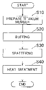
FIG I is a flowchart illustrating a manufacturing method of a separator
according to an example embodiment of the invention;
FIG. 2 is a graph showing the distribution of the atomic percent of carbon
atoms
in the depth direction of a separator member;
FIG. 3 is a graph showing the distribution of the atomic percent of carbon
atoms
in the depth direction of the separator member after heat treatment;
FIG. 4 is a view of the separator member produced according to the method
shown in FIG. 1;
FIG 5 is a view showing the results of a peel test for a separator produced
when
the conditions of the buffing in step S20 were changed;
FIG. 6 is a view showing the results of a peel test for a separator produced
when
conditions of the heat treatment in step S40 were changed; and
FIG 7 is a graph showing the adhesiveness in the cases of a separator member
(C) produced according to the method shown in the flowchart in FIG 1, a
separator
member (A) produced without buffing or heat treatment, and a separator member
(B)
produced without heat treatment.
DETAILED DESCRIPTION OF THE PREFERRED EMBODIMENTS
[0014] Next, the invention will be described in the following order: A.
Example embodiments, B. Test examples, C. Modified examples
[0015] A. Example embodiments
FIG. 1 is a flowchart illustrating a manufacturing method of a separator
CA 02652497 2010-10-07
according to an example embodiment of the invention. In step S 10, a titanium
separator
member is first prepared. This separator member can be a plate-like member
formed of
JIS 1 type pure titanium, for example. Incidentally, a carbide layer which
includes TiC
formed from a reaction between the titanium and a carbon inclusion of a
rolling solution
5 or the like that was applied at the time of press forming, on the surface of
the titanium
separator member.
[00161 FIG 2 is a graph showing the distribution of the atomic percent of
carbon atoms in the depth direction of the separator member. The horizontal
axis of the
graph represents the position d in the depth direction of the separator
member, and the
vertical axis of the graph represents the atomic percent of carbon atoms
(atomic %).
The numerical values in the graph in FIG 2 are values obtained by X-ray
Photoelectron
Spectroscopy or XPS. In this specification the carbon content will be
evaluated by the
atomic percent of carbon atoms measured according to this method.
[00171 In FIG 2, C1 indicates the distribution of the atomic percent of carbon
atoms in the depth direction of the titanium separator member that was
prepared in step
S10. As is evident from FIG 2, with the titanium separator member that was
prepared
in step S 10, the maximum value of the atomic percent of carbon atoms in the
range RdO
from the surface (depth of 0) to 50 nm deep exceeds 30% and the average value
is more
than 5%.
[00181 In step S20, the carbide on the surface layer SL is removed by buffing
the surface of the separator member. Incidentally, the surface layer of a
member refers
to a portion of the member which includes the surface of the member. In this
case, the
surface of the separator member is buffed until a layer of material
approximately 20 nm
thick has been removed.
[00191 The thickness of the surface layer removed in step S20 can be
determined according to the distribution of the atomic percent of carbon atoms
in the
separator member that was prepared in step S 10. In this case, in a separator
member in
which the distribution of the atomic percent of carbon atoms is as shown by Cl
in FIG 2,
a surface layer SL approximately 20 nm thick is removed so that the atomic
percent of
0 . i FT3070072-PC;1
carbon atoms up to 50 nm deep from the surface of the titanium metal portion
after the
surface layer has been removed is no more than 5%.
[00201 In FIG. 2, C2 indicates the distribution of the atomic percent of
carbon
atoms in the depth direction of the separator member after step S20 has been
performed.
= As is evident from FIG. 2, after step S20 the atomic percent of carbon atoms
is below the
average value of 5% in the range from the surface (depth of 0) to 50 rim deep
in the
titanium separator member. Incidentally, at C2 in FIG. 2, the percentage of
carbon is not
the highest at the surface (depth of 0). Rather, the percentage of carbon is
the highest
near a depth of 2 to 3 rim. This is thought to be because the amount of carbon
is less
near the surface of the separator member than it is inside the member where
there is
100% metal because of surface asperities.
100211 Then in step S30 in FIG. 1, the surface: of the separator member is
gold
plated by sputtering. More specifically, in a 10-2 Toff argon atmosphere,
sputtering is
performed with gold so that the plating layer-becomes approximately 10 nm
thick. At
this time, H} from the small amount of H2O in the environment is introduced
onto the
gold plating layer.
[0022) In step S40 in FIG 1, the gold plated separator member is heat treated
for approximately 30 minutes at a target temperature of 400 C with the actual
heating
temperature, being 220 C to 450 C in a 10'2 Torr argon atmosphere. 'Performing
this
kind of heat treatment removes hydrogen that'-is present near the boundary
surface of the
gold,plating layer and the titanium layer as hydrogen gas outside the sample
or diffuses it
in the titanium metal layer. .
[00231 FIG. 3 is a, graph showing the distribution of the atomic percent of
hydrogen atoms in the depth direction of the separator member after heat
treatment has
been performed. The horizontal axis of.the,graph represents the position d in
the depth
direction of the separator member, and the vertical axis represents the atomic
percent of
hydrogen atoms (atomic %). The numerical values in the graph, in FIG. 3 are
values
obtained by measurements according to Rutherford Backscattering Spectroscopy
or RBS.
In this specification the hydrogen content will be-evaluated by the atomic
percent of
CA 02652497 2008-11-17 <<' AMENDED SHEET
CA 02652497 2008-11-17
WO 2007/138436 PCT/IB2007/001375
7
hydrogen atoms measured according to this method. Incidentally, with
Rutherford
Backscattering Spectroscopy there is error of several nm in the depth
direction.
[0024] As is evident from the graph in FIG. 3, the atomic percent of hydrogen
atoms is highest near the boundary surface of the titanium layer G and the
gold plating
layer P about 10 nm deep. However, as a result of the heat treatment in step
S40, the
atomic percent of hydrogen atoms is at most no more than 1 % in the range Rd
of plus or
minus 10 nm of the boundary surface of the gold plating layer P and the
titanium layer G.
Incidentally, in the graph in FIG. 3, the atomic percent of hydrogen atoms is
approximately half at a depth of 3 nm on the titanium layer G side from the
peak. Also,
the reason for the percentage of hydrogen being higher near the surface (depth
of 0)
which is at the left end in the graph than at a depth of several nm is thought
to be because
OH based hydrogen that was adhered to the gold plated surface is detected.
[0025] FIG 4 is a view of the separator member produced by the method
shown in FIG. 1. In the manner described above, it is possible to manufacture
a titanium
separator member in which the atomic percent of hydrogen atoms is no more than
1 % in
the range Rd near the boundary surface BS of the gold plating layer P and the
titanium
layer G as the bare metal portion. Incidentally, in this specification, the
phrase "near the
boundary surface" when describing the atomic percent of atoms of an element
refers to a
range between the position 10 nm above the boundary surface BS and the
position l0nm
below the boundary surface BS, and is a range that includes the plating layer
P or the bare
metal portion G.
[0026] Also, in the process in step S30, in which the gold plating layer is
applied to the titanium metal surface, as well as the process thereafter, the
atomic percent
of carbon atoms in the titanium metal does not increase. Therefore, with the
titanium
separator member obtained by the method in FIG 1, the atomic percent of carbon
atoms
is on average no more than 5% at a depth of 50 nm near the boundary surface BS
(which
corresponds to the titanium metal surface after step S20 and before step S30)
of the gold
plating layer P and the titanium layer G (see C2 in FIG. 2).
[0027] B. Test example
CA 02652497 2010-10-07
8
B1. Test example 1
A plurality of separator members were produced under a variety of different
buffing conditions in step S20 in FIG 1 so that the average value of the
atomic percent of
carbon atoms in the range from the uppermost surface of the separator member
after
buffing to a depth of 50 nm (hereinafter this range will be referred to as the
"surface
portion") for each of the separator members is different and within a range
from I% to
14%. Incidentally, in the procedure for producing the separator members, the
processes
of steps S20 and thereafter are the same. The plurality of separator members
produced
under different conditions in this way were then immersed in a 80 C sulfuric
acid
solution with a pH value of 2 for 24 hours, after which they were subjected to
a peel test.
The test was performed according to the tape peel test prescribed by JIS.
[0028] FIG 5 is a view showing the results of the peel test for a separator
produced when the conditions of the buffing in step S20 were changed. In FIG
5, the
black dots show the test results of the separator members produced under
different
conditions. The horizontal axis in the middle indicates the atomic percent of
carbon
atoms. The points shown on the line above the horizontal axis indicate the
separator
members in which peeling occurred while the dots on the line below the
horizontal axis
indicate the separator members in which peeling did not occur. As is evident
from FIG
5, when the JIS 1 type titanium that was employed in the example embodiment
described
above is used as the metal of the bare metal portion G and gold plating is
applied, the
gold plating layer P tends to peel away when the average value of the atomic
percent of
carbon atoms exceeds 5%. When the carbon content is less than 5%, the gold
plating
layer P does not peel away easily.
[0029] B2. Test example 2
A plurality of separator members were produced under a variety of different
heat
treatment conditions in step S40 in FIG 1 so that the maximum value of the
atomic
percent of hydrogen atoms near the boundary surface of the bare metal portion
and the
plating layer after heat treatment for each of the separator members is
different and
within a range from 0.3% to 2.3%. Incidentally, in the procedure for producing
the
CA 02652497 2010-10-07
9
separator members, the processes of the steps other than step S40 are the
same. The
plurality of separator members produced under different conditions in this way
were then
immersed in a 80 C sulfuric acid solution with a pH value of 2 for 24 hours,
after which
they were subjected to the peel test. The test was performed according to the
tape peel
test prescribed by JIS.
[0030] FIG. 6 is a view showing the results of the peel test for a separator
produced when the conditions of the heat treatment in step S40 were changed.
In FIG 6,
the horizontal axis in the middle indicates the atomic percent of hydrogen
atoms. The
other notation in FIG 6 is the same as in FIG 5. As is evident from FIG 6,
when the JIS
1 type titanium that was employed in the example embodiment described above is
used as
the metal of the bare metal portion G and gold plating is applied, the gold
plating layer P
tends to peel away when the maximum value of the atomic percent of hydrogen
atoms
exceeds 1%. When the hydrogen content is less than 1%, the gold plating layer
P does
not peel away easily.
[0031] B3. Test example 3
FIG 7 is a graph showing the adhesiveness in the cases of a separator member
(C) produced according to the method shown in the flowchart in FIG 1, a
separator
member (A) produced without buffmg in step S20 or heat treatment in step S40,
and a
separator member (B) produced without heat treatment in step S40.
Incidentally, the
adhesiveness is a value obtained from the peel test that is proportional to
the reciprocal of
the ratio of the area of the portion where peeling occurred to the overall
area to which
tape was applied.
[0032] As is evident from FIG 7, the separator member (B) that was buffed but
not heat treated has approximately 1.3 times the adhesiveness of the separator
member
(A) that was neither buffed (in step S20 in FIG 1) nor heat treated (in step
S40 in FIG 1).
Also, the separator member (C) that was both buffed and heat treated has 1.4
times the
adhesiveness of the separator member (A) that was neither buffed nor heat
treated.
[0033] B4. Analysis
The reason why the precious metal plating tends to peel away from the metal
CA 02652497 2008-11-17
ned>.:
'3.'r N070072-PCT
member is.thought to be.as follows. That is, the carbide present near the
surface of the
metal member before the plating was applied gradually reacts with oxygen at
the
boundary surface of the plating layer after the plating is applied. Then the
carbide
changes to oxide. When the carbide (such as TiC) on the metal member side at
the
5 boundary surface of the plating layer changes to oxide (such as TiO2), the
spacing of the
crystal lattice changes. Accordingly, the plating layer ends up, being out of
alignment
with the oxide layer which reduces the adhesiveness between the oxide layer
and the
plating layer. It is thought that as a result the precious metal plating tends
to peel away
from the metal member.
10 . '[0034]' The carbide in the surface of the metal member before plating is
applied
is present at a depth ranging from several tens of nm to several hundred nm in
the metal
surface. In the foregoing example embodiment, the likelihood of the plating
layer
peeling away after the precious metal plating is applied is reduced by first
removing this
carbide layer from the precious metal plating (see step S20 in FIG. 1, and
FIG. 2). When
the bare metal portion's titanium, for example, the Ti that is exposed on the
surface of
the bare metal portion after the carbide has been removed resists oxidation
more than the
TiC which is carbide does.
[0035] Incidentally, the oxide reaction described above may occur by, for
example, acidic liquid passing through a crack in the plating layer and
reaching the
boundary surface of the plating layer and the metal member. When the plating
layer is. applied by sputtering, the plating material accumulates in columns
in the direction of
thickness, making it more vulnerable to cracking than plating applied by a wet
process.
Therefore, plating applied by a wet process is more suitable than that by
sputtering in
some applications. =
[0036] On the other hand, another reason why the precious metal plating tends
to peel away from the metal member is thought to be as follows. That is, when
applying
precious metal plating under a high vacuum in. an.argon environment, hydrogen
ions in
small amounts of H2O that is present are introduced into the plating layer:
Then these
hydrogen ions gather at the boundary surface of the metal member and the
precious metal
` AMENDED SHEET >< 008
CA 02652497 2008-11-17
WO 2007/138436 PCT/IB2007/001375
11
plating layer by dispersion and form a hydride (for example, titanium hydride
TiH or
TiH2 when the bare metal portion is titanium). Gold hydride is extremely
brittle so the
hydride layer portion is susceptible to breaking. It is thought that the
plating layer ends
up peeling away because this hydride layer breaks. In the foregoing example
embodiment, the heat treatment after the plating has been applied disperses
the hydrogen
present in the boundary surface BS of the plating layer P and the bare metal
portion G
throughout the entire metal member. This is why it is thought that the plating
layer of
the member of the foregoing embodiment is less likely to peel away.
[0037] C. Modified examples
The invention is not limited to only the example embodiments and examples
described above. On the contrary, the invention can be modified without
departing from
the scope thereof. For example, the invention may also be realized in the form
of a
separator of a fuel cell, a manufacturing method of a separator of a fuel
cell, a fuel cell
that includes a titanium separator, and a manufacturing method of that fuel
cell, and the
like. Also, the following mode, for example, is also possible.
[0038] C1. Modified example 1
In the foregoing example embodiment, the separator is formed of JIS 1 type
titanium. However, the material of the plated metal member is not limited to
this.
That is, the material of the member that is plated with precious metal may
also be JIS 2 or
JIS 3 type titanium. Also, other than pure titanium as prescribed by JIS, a
titanium alloy
that includes large amounts of other metals may also be used. In addition, the
material
of the member that is plated with a precious metal may also be stainless
steel. This
allows the member to be manufactured at a lower cost than a titanium member.
[0039] That is, the foregoing example embodiment is also effective when the
bare metal portion of the precious metal plated metal member is formed of
metal that
forms a passive film on the surface in a normal temperature atmosphere that
includes
oxygen. This kind of metal member will not corrode over an extended period of
time
and is thus able to perform stably as part of a fuel cell, for example.
[0040] Incidentally, in a mode in which precious metal plating is applied to a
CA 02652497 2008-11-17
WO 2007/138436 PCT/IB2007/001375
12
metal member made of stainless steel, the heat treatment corresponding to step
S40 in
FIG. I can also be omitted because hydride does not form as easily on
stainless steel as it
does on titanium.
[0041] C2. Modified example 2
In the foregoing example embodiment, the plating layer formed on the metal
member is a layer of gold. Alternatively, however, the plating layer formed on
the metal
member may also be of another material such as platinum or copper, for
example.
However, the plating layer preferably has greater conductivity than the oxide
of the
material of the metal member, and even more preferably is of a precious metal.
[0042] C3. Modified example 3
In the foregoing example embodiment, the titanium separator member that is
prepared in step S 10 is a member in which the average value of the atomic
percent of
carbon atoms in the range RdO of 50 nm deep from the surface (depth of 0) is
no more
than 5%. However, the atomic percent of carbon atoms of the titanium separator
member that is prepared in step S 10 may also be another value. For example,
the
average value of the atomic percent of carbon atoms within a predetermined
range from
the surface of the separator member maybe made to be no more than 6%. However,
the
average value of the atomic percent of carbon atoms within a predetermined
range from
the surface is preferably 4% to 6%, more preferably 4.5% to 5.5%, and even
more
preferably 4.8% to 5.2%.
[0043] C4. Modified example 4
In the foregoing example embodiment, a surface layer approximately 20 nm
thick of the separator member is removed before the plating is applied.
However, the
thickness of the surface layer that is removed before the plating is applied
may vary
according to the distribution of the atomic percent of carbon atoms of the
member. That
is, a process may be performed in which a portion that has a higher carbon
content than
the surface portion of the bare metal portion after the removal process is
removed as the
surface layer before the plating is applied. In other words, the process of
removing the
surface layer may be one which removes a portion that includes the surface of
the
CA 02652497 2008-11-17
1S TFN070072-PCT
member such that the carbon content of the surface portion that is to be
plated is reduced. -
[0044] Incidentally, the term "surface portion" :of the bare metal portion
refers
to a range up to. 50 inn deep from the surface of the bare metal portion.
Also, the carbon
content of the surface portion of the bare metal-.portion is evaluated by the
average value
of the atomic percent of carbon atoms in the surface portion of the bare metal
portion.
[0045] In the process for removing the surface layer, a polishing method other
than buffing may also be used and other machining such as grinding may also be
performed. Also, the surface layer may be removed by short blasting or laser.
[0046] 'Also in the foregoing example embodiment, the atomic percent of
carbon' atoms in the bare metal portion after the surface layer has been
removed is less
than-5% (see C2 in FIG 2). However, the atomic percent of carbon atoms in the
bare
metal portion after the surface layer has been removed can be any one of a
variety of
values depending on the structure of the bare metal portion, the precious
metal used for
plating, and the plating method and the like. However, the atomic percent of
carbon
atoms in the surface portion of the bare metal portion after the surface layer
has been
removed is preferably no more than 30%, more preferably no more than 10%, and
even
more preferably no more than 5%.
[0047] C5. Modified example 5
In the foregoing example etbodiment, sputtering is performed in step S30
directly after the buffing in step S20 in FIG 1. However, argon sputtering may
also be
performed to. remove the oxide (such as TiO2 when the bare metal portion is
formed of
titanium) formed on the surface of the metal member after the 'buffing and
before the
plating is applied. Accordingly, even if oxide forms on the surface of the
metal member
before the plating is applied, that oxide can be removed. As a result, the
bond between
25' the plating layer and the metal material can be made even stronger.
[0048] C6. Modified example ''6
In the foregoing example embodiment, when the-gold plating is applied to the
surface of the separator member, it is sputtered on in-a 10-2 Torr argon
atmosphere.
However, when applying precious, metal plating to the surface of the metal
member,
AMENDED SHEET
CA 02652497 2008-11-17
WO 2007/138436 PCT/IB2007/001375
14
various temperatures, pressures including atmospheric pressure, and apply
times can be
used. Also, the process can be performed in an atmosphere of another inert gas
such as
in a helium atmosphere. That is, the heat treatment can be performed in an
inert
atmosphere. Here, the term "inert atmosphere" refers to an atmosphere in which
metal
oxide will not be form on the bare metal portion even if the heat treatment is
performed.
[0049) C7. Modified example 7
In the foregoing example embodiment, when heat treating the separator member,
the treatment is performed at a target temperature of 400 C for 30 minutes in
a 10-2 argon
atmosphere. However, when heat treating the metal member, various
temperatures,
pressures, and heat treating times can be used. Also, the treatment can be
performed in
an atmosphere of another inert gas such as in a helium atmosphere. However,
the
heating temperature is preferably between 220 C and 500 C, inclusive, more
preferably
between 350 C and 450 C, inclusive, and even more preferably between 380 C and
420 C, inclusive.
[0050] C8. Modified example 8
In the foregoing example embodiment, the hydrogen content at the boundary
surface of the plating layer and the bare metal portion is no more than 1 %.
However,
the hydrogen content at the boundary surface of the plating layer and the bare
metal
portion may be another value depending on the structure of the bare metal
portion, the
precious metal used for plating, and the plating method and the like. However,
the
hydrogen content near the boundary surface of the plating layer and the bare
metal
portion is preferably no more than 1 %, more preferably no more than 0.7 %,
and even
more preferably no more than 0.5%.
[0051] C9. Modified example 9
A fuel cell may also be manufactured using separators that were manufactured
according to the method of the foregoing example embodiment. This fuel cell
includes
the separators and membrane electrode assemblies (MEA) that generate
electricity
through an electrochemical reaction with a reaction gas. Each MEA includes an
electrolyte membrane and electrodes provided on both sides of the electrolyte
membrane.
CA 02652497 2008-11-17
WO 2007/138436 PCT/IB2007/001375
The separators are then provided on the sides of the electrodes opposite the
electrolyte
membrane such that one MEA is separated from another by a separator, with the
separators contacting the electrodes via the portions that have been gold
plated.
[0052] With this kind of fuel cell, the separators are formed of a metal that
5 forms a passive film on the surface. As a result, the separators will not
corrode and are
thus able to perform stably for an extended period of time. Also, the
separators contact
the electrodes via the portions that have been plated with a precious metal so
the contact
resistance between the separators and the electrodes is small. Accordingly,
the power
generating efficiency is higher than it is when the contact portions between
the separators
10 and the electrodes are not plated with a precious metal. Furthermore, with
the portions
that have been plated with the precious metal, oxide does not easily form at
the boundary
surface between the precious metal layer and the bare metal portion of the
separator, and
as a result, the precious metal plating does not easily peel away.