Language selection

Search

Patent 2652661 Summary

Third-party information liability

Some of the information on this Web page has been provided by external sources. The Government of Canada is not responsible for the accuracy, reliability or currency of the information supplied by external sources. Users wishing to rely upon this information should consult directly with the source of the information. Content provided by external sources is not subject to official languages, privacy and accessibility requirements.

Claims and Abstract availability

Any discrepancies in the text and image of the Claims and Abstract are due to differing posting times. Text of the Claims and Abstract are posted:

  • At the time the application is open to public inspection;
  • At the time of issue of the patent (grant).
(12) Patent: (11) CA 2652661
(54) English Title: A STRINGER FOR AN AIRCRAFT WING AND A METHOD OF FORMING THEREOF
(54) French Title: LISSE DESTINEE A UNE AILE D'AVION ET PROCEDE DE FORMATION DE CELLE-CI
Status: Expired and beyond the Period of Reversal
Bibliographic Data
(51) International Patent Classification (IPC):
  • B64C 3/18 (2006.01)
(72) Inventors :
  • CHILDS, THOMAS (United Kingdom)
(73) Owners :
  • AIRBUS OPERATIONS LIMITED
(71) Applicants :
  • AIRBUS UK LIMITED (United Kingdom)
(74) Agent: BORDEN LADNER GERVAIS LLP
(74) Associate agent:
(45) Issued: 2014-09-16
(86) PCT Filing Date: 2007-05-23
(87) Open to Public Inspection: 2007-12-21
Examination requested: 2012-05-09
Availability of licence: N/A
Dedicated to the Public: N/A
(25) Language of filing: English

Patent Cooperation Treaty (PCT): Yes
(86) PCT Filing Number: PCT/GB2007/001927
(87) International Publication Number: WO 2007144563
(85) National Entry: 2008-11-18

(30) Application Priority Data:
Application No. Country/Territory Date
0611875.6 (United Kingdom) 2006-06-15

Abstracts

English Abstract


The present invention relates to a stringer for an aircraft wing and a method
of forming
such a stringer in which the stringer is formed from a single piece of
material and has
differential strength along its length. The stringer comprises two side
panels, at least
one of which is perforated to form a set of holes spaced along the length of
the stringer.
The volume of holes increases towards the wing tip end of the stringer thereby
enabling
the load capacity of the stringer to be tailored along its length.


French Abstract

La présente invention concerne une lisse (105) destinée à une aile d'avion et un procédé de formation d'une telle lisse dans lequel la lisse (105) est formée d'une seule pièce de matériau et présente un niveau de résistance différencié le long de sa longueur.

Claims

Note: Claims are shown in the official language in which they were submitted.

6
Claims
1. A stringer for an aircraft wing comprising:
two spaced apart flanges for attachment to a wing cover panel, said flanges
having opposing inner ends;
two side panels each integral with a respective one of said inner ends of said
flanges and extending away from said flanges in converging planes;
a top panel arranged in a plane generally parallel to said flanges and being
integral with and inter joining said side panels; and
at least one of said side panels being perforated to form a set of holes
spaced
along the length of the stringer, the volume of said holes varying along the
stringer such
that the volume of said holes increases towards the wing tip end of said
stringer.
2. A stringer according to claim 1 in which the volume of said holes
decreases
around a point input load to the stringer.
3. A stringer according to claim 1 or 2 in which said holes are centred
along a
straight line.
4. A stringer according to any one of claims 1 to 3 in which said holes are
centred
along a curved line.
5. A stringer according to any one of claims 1 to 4 in which both said side
panels
are perforated.
6. A stringer according to claim 5 in which said set of holes in each said
side panel
have the same size and configuration.
7. A stringer according to any one of claims 1 to 6 in which said holes are
circular.
8. A stringer according to any one of claims 1 to 7 in which the centres of
said
holes are evenly spaced apart.

7
9. A method for creating a stringer for an aircraft wing comprising the
steps of:
a) forming a stringer blank having:
a pair of spaced apart flanges for attachment to a wing cover panel, said
flanges having opposing inner ends; a pair of side panels each integral with a
respective one of an inner end of said flanges and extending away from said
flanges in converging planes;
a top panel arranged in a plane generally parallel to said flanges and
being integral with and inter joining said side panels; and
b) perforating at least one of said side panels to form a set of holes
spaced
along the length of the stringer, the volume of said holes varying along the
stringer, such
that the volume of said holes increases towards the wing tip end of said
stringer.
10. A method according to claim 9 in which the volume of said holes
decreases
around a point input load to the stringer.
11. A method according to claim 9 or 10 in which said holes are centred
along a
straight line.
12. A method according to any one of claims 9 to 11 in which said holes are
centred
along a curved line.
13. A method according to any one of claims 9 to 12 in which both said side
panels
are perforated.
14. A method according to claim 13 in which said set of holes in each said
side
panel have the same size and configuration.
15. A method according to any one of claims 9 to 14 in which said holes are
circular.
16. A method according to any one of claim 9 to 15 in which the centres of
said
holes are evenly spaced apart.

8
17. A method according to any one of claims 9 to 16 in which said stringer
blank is
formed by extrusion.
18. A method according to any one of claims 9 to 17 in which said stringer
blank is
formed from a metal or a metal alloy.

Description

Note: Descriptions are shown in the official language in which they were submitted.


CA 02652661 2008-11-18
WO 2007/144563
PCT/GB2007/001927
1
A Stringer for an Aircraft Wing and a Method of Forming thereof
Field of Invention
The present invention relates to a stringer for an aircraft wing and a method
of forming
such a stringer.
Background of the Invention
The core of an aircraft wing is a section called a wing box. The wing box is
fared into
the aircraft fuselage and runs from the root towards the tip of the wing. The
wing box
provides the central sections of the upper and lower aerofoil surfaces for the
wing in
addition to attachment points for engines and control surfaces such as
ailerons, trim
flaps and airbrakes. The aerofoil surfaces of the wing box are provided by
panels
referred to as wing covers. The wing covers include a number of structural
elements
called stringers, which run within the wing box structure from the root
towards the tip.
The stringers are arranged to provide the necessary structural stability and
integrity to
enable the wing covers to cope with the operational loads on the wing.
When building aircraft structures, one of many considerations is the balance
between
weight and strength. In other words, structures need to be as light as
possible while
providing the necessary strength and structural integrity to perfonn properly
under
operational loads. The loads on a wing vary along its span and typically
reduce towards
the wing tip. Therefore, stringers can be built to have strength that varies
along their
length, thus reducing their overall weight. Stringers are commonly created by
joining or
splicing stringer sections, each section having weight characteristics
tailored to its
expected loading. Alternatively, a single stringer can be provided and
machined to a
varying degree along the span so as to reduce unnecessary weight.
A problem with splicing or joining sections of stringer is that it adds extra
weight and
complexity to the wing box. A problem with machining a single stringer is that
the
amount by which the stringer can be modified is limited.

CA 02652661 2008-11-18
WO 2007/144563
PCT/GB2007/001927
2
Summary of the Invention
An embodiment of the invention provides a stringer for an aircraft wing
comprising:
two spaced apart flanges for attachment to a wing cover panel, the flanges
having
opposing inner ends;
two side panels each integral with a respective one of the inner ends of the
flanges and
extending away from the flanges in converging planes;
a top panel arranged in a plane generally parallel to the flanges and being
integral with
and inter joining the side panels; and
at least one of the side panels being perforated to form a set of holes spaced
along the
length of the stringer.
The volume of the holes may vary along the stringer. The volume of the holes
may
increase towards the wing tip end of the stringer. The volume of the holes may
decrease
around a point input load to the stringer. The holes may be centred along a
straight line.
The holes may be centred along a curved line. Both the side panels may be
perforated.
The set of holes in each side panel may have the same size and configuration.
The holes
may be circular. The centres of the holes may be evenly spaced apart.
Another embodiment provides a method for creating a stringer for an aircraft
wing
comprising the steps of:
a) forming a stringer blank having:
a pair of spaced apart flanges for attachment to a wing cover panel, the
flanges having
opposing inner ends; a pair of side panels each integral with a respective one
of an inner
end of the flanges and extending away from the flanges in converging planes;
a top panel arranged in a plane generally parallel to the flanges and being
integral with
and inter joining the side panels; and
b) perforating at least one of the side panels to form a set of holes spaced
along the
length of the stringer.
The stringer blank may be formed by extrusion. The stringer blank may be
formed from
a metal or a metal alloy.

CA 02652661 2008-11-18
WO 2007/144563
PCT/GB2007/001927
3
Brief Description of the Drawings
Embodiments of the invention will now be described, by way of example only,
with
reference to the accompanying drawings in which:
Figure 1 is a plan view of an aircraft;
Figure 2 is a cross-sectional view of a wing box of the aircraft of figure 1;
Figure 3 shows a side perspective view of a stringer in the wing box of figure
2;
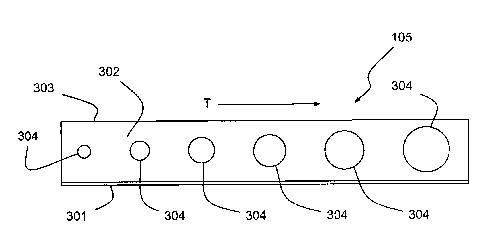
Figure 4 shows a side view of the stringer of figure 3; and
Figure 5 shows a side view of a stringer in another embodiment.
Detailed Description of Embodiments of the Invention
With reference to figure 1, an aircraft 101 comprises wings 102 attached to a
fuselage
103. The wings 102 comprise a central structural element 104 in the form of a
wing
box. The wing box 104 runs from the root to the tip of each wing 102 and
between the
leading and trailing edges of the wing. The wing box 104 comprises a number of
structural elements 105 in the form of stringers, which run from the root to
the tip of
each wing box 104.
With reference to figure 2, the wing box 104 is constructed from two side
members 201
in the form of spars, which provide attachment points for the leading and
trailing edge
structures (not shown) of the wing 102. The upper and lower surfaces 202, 203
of the
wing box 104 are each formed from wing cover panels, which provide the upper
and
lower aerofoil surfaces of the wing 102. The stringers 105 are attached to the
interior
surface of the wing cover panels 202, 203.
With reference to figure 3, the stringers 105 are formed by extruding blank
stringers
from aluminium alloy. The blank stringers have two spaced apart attachment
members
301 in the form of flanges for providing attachment points to a wing cover
203. Side
panels 302 extend away from the interior ends of the flanges 301 in converging
planes.
The side panels 302 are joined by a top panel 303, which forms a crown to the
stringer
blank cross-section. Since the stringer blanks are extruded, the flanges 301,
side panels
302 and crown 303 are integrally formed. The finished stringer 105 is produced
by
machining holes 304 in the side panels 302 of the blank stringer to remove
amounts of

CA 02652661 2008-11-18
WO 2007/144563
PCT/GB2007/001927
4
material along its length. The holes 301 serve to minimise the weight of the
stringer,
while the pattern and size of the holes 304 are designed to tailor the
structural integrity
imparted by the stringer 105 along the length of an attached wing cover panel.
In the stringer of figure 3, the size of the holes 304 increases in the
direction of the wing
tip end of the stringer 105 indicated by arrow T. The pattern of the holes is
such that
their edges are equally spaced from each other and their centres are aligned
on a straight
line substantially parallel to the plane of attachment with the wing cover 203
as shown
in figure 4. Thus, a wing panel attached to the stringer 105 would have a
relatively high
load capacity at its end near the wing root and progressively less capacity in
the
direction T towards the wing tip end. The holes 304 remove increasing amounts
of
material from the side panels 302 in the direction T, thus minimising the
weight of the
wing box.
In another embodiment shown in figure 5, the stringer 105 has a set of holes
501 formed
in its side panels 302, which are relatively large at the wing root end and
then reduce in
size before becoming relatively large again towards the wing tip end of the
stringer 105.
The central portion of the stringer where the holes 501 are smaller will thus
provide
greater structural integrity to an attached wing panel so as to enable
additional loading
in the central part of the wing. This may be required, for example, to provide
an
attachment point for an engine or other equipment where there is a point input
load to
the stringer.
In another embodiment, the holes are centred along a curved line in the plane
of the side
panels. In a further embodiment, the holes are centred on a line converging
with the
plane of the wing cover. In another embodiment, the holes are of constant size
or area
or volume. In a further embodiment, the holes are spaced apart by varying
distances. In
another embodiment, the area or volume or spacing of the holes is modified
around a
load point in the stringer. In a further embodiment, the sets of holes are the
same in
each side panel but staggered relative to each other. Such staggering
facilitates the
attachment of items to the stringer such as rib cleats, which can be attached
without
using blind fastenings. In another embodiment, the holes are non-circular. For

CA 02652661 2014-01-10
example, the holes maybe ovoid, triangular, rhomboid or other polyhedral
shape. In a
further embodiment, the holes are provided in only a part of one of the side
panels for at
least a part of the stringer.
5 The holes provided in the embodiments of the invention also enable
inspection of the
interior surfaces of the stringer and otherwise concealed sections of wing
cover.
Furthermore, the holes provide ventilation for the otherwise enclosed space.
Lack of
such ventilation can lead to corrosion. The controlling or modifying the
performance of
a stringer in the manner described reduces the size of the extrusion envelope
required to
form the stringer. This therefore reduces the material required to produce a
stringer
when compared to a manufacture processes in which the cross section of an
extruded
stringer is modified.
As will be understood by those skilled in the art, machining of the stringer
blank may be
carried out by any suitable process such as milling, etching, abrading,
punching or
drilling. Furthermore, the stringers may be formed from any suitable material
such as a
metal, metal alloy or other suitable non-metallic material.
The scope of the claims should not be limited by particular embodiments set
forth
herein, but should be construed in a manner consistent with the specification
as a whole.

Representative Drawing
A single figure which represents the drawing illustrating the invention.
Administrative Status

2024-08-01:As part of the Next Generation Patents (NGP) transition, the Canadian Patents Database (CPD) now contains a more detailed Event History, which replicates the Event Log of our new back-office solution.

Please note that "Inactive:" events refers to events no longer in use in our new back-office solution.

For a clearer understanding of the status of the application/patent presented on this page, the site Disclaimer , as well as the definitions for Patent , Event History , Maintenance Fee  and Payment History  should be consulted.

Event History

Description Date
Time Limit for Reversal Expired 2017-05-23
Inactive: Correspondence - Transfer 2016-07-12
Letter Sent 2016-05-24
Grant by Issuance 2014-09-16
Inactive: Cover page published 2014-09-15
Inactive: Final fee received 2014-06-27
Pre-grant 2014-06-27
Notice of Allowance is Issued 2014-05-08
Letter Sent 2014-05-08
Notice of Allowance is Issued 2014-05-08
Inactive: Approved for allowance (AFA) 2014-05-06
Inactive: Q2 passed 2014-05-06
Amendment Received - Voluntary Amendment 2014-01-10
Inactive: S.30(2) Rules - Examiner requisition 2013-07-10
Letter Sent 2012-05-22
Request for Examination Requirements Determined Compliant 2012-05-09
All Requirements for Examination Determined Compliant 2012-05-09
Request for Examination Received 2012-05-09
Inactive: Office letter 2011-05-27
Letter Sent 2011-05-20
Inactive: Cover page published 2009-03-12
Inactive: Notice - National entry - No RFE 2009-03-10
Inactive: First IPC assigned 2009-03-04
Application Received - PCT 2009-03-03
National Entry Requirements Determined Compliant 2008-11-18
Application Published (Open to Public Inspection) 2007-12-21

Abandonment History

There is no abandonment history.

Maintenance Fee

The last payment was received on 2014-04-23

Note : If the full payment has not been received on or before the date indicated, a further fee may be required which may be one of the following

  • the reinstatement fee;
  • the late payment fee; or
  • additional fee to reverse deemed expiry.

Please refer to the CIPO Patent Fees web page to see all current fee amounts.

Owners on Record

Note: Records showing the ownership history in alphabetical order.

Current Owners on Record
AIRBUS OPERATIONS LIMITED
Past Owners on Record
THOMAS CHILDS
Past Owners that do not appear in the "Owners on Record" listing will appear in other documentation within the application.
Documents

To view selected files, please enter reCAPTCHA code :


To view images, click a link in the Document Description column. To download the documents, select one or more checkboxes in the first column and then click the "Download Selected in PDF format (Zip Archive)" or the "Download Selected as Single PDF" button.

List of published and non-published patent-specific documents on the CPD .

If you have any difficulty accessing content, you can call the Client Service Centre at 1-866-997-1936 or send them an e-mail at CIPO Client Service Centre.


Document
Description 
Date
(yyyy-mm-dd) 
Number of pages   Size of Image (KB) 
Description 2008-11-18 5 258
Representative drawing 2008-11-18 1 10
Drawings 2008-11-18 3 51
Claims 2008-11-18 3 86
Abstract 2008-11-18 1 58
Cover Page 2009-03-12 1 35
Description 2014-01-10 5 243
Claims 2014-01-10 3 77
Abstract 2014-01-10 1 13
Representative drawing 2014-05-07 1 5
Cover Page 2014-08-21 1 35
Reminder of maintenance fee due 2009-03-10 1 111
Notice of National Entry 2009-03-10 1 193
Reminder - Request for Examination 2012-01-24 1 126
Acknowledgement of Request for Examination 2012-05-22 1 177
Commissioner's Notice - Application Found Allowable 2014-05-08 1 161
Maintenance Fee Notice 2016-07-05 1 182
PCT 2008-11-18 3 86
Correspondence 2011-05-27 2 32
Correspondence 2014-06-27 1 34