Language selection

Search

Patent 2652685 Summary

Third-party information liability

Some of the information on this Web page has been provided by external sources. The Government of Canada is not responsible for the accuracy, reliability or currency of the information supplied by external sources. Users wishing to rely upon this information should consult directly with the source of the information. Content provided by external sources is not subject to official languages, privacy and accessibility requirements.

Claims and Abstract availability

Any discrepancies in the text and image of the Claims and Abstract are due to differing posting times. Text of the Claims and Abstract are posted:

  • At the time the application is open to public inspection;
  • At the time of issue of the patent (grant).
(12) Patent: (11) CA 2652685
(54) English Title: ENGINE EXHAUST SYSTEM WITH DIRECTIONAL NOZZLE
(54) French Title: SYSTEME D'ECHAPPEMENT DE MOTEUR AVEC BUSE DIRECTIONNELLE
Status: Granted and Issued
Bibliographic Data
(51) International Patent Classification (IPC):
  • B64D 33/04 (2006.01)
  • F01N 13/08 (2010.01)
  • F02K 1/00 (2006.01)
(72) Inventors :
  • HOLLIMON, CHARLES (United States of America)
  • BARBER, JOHN (United States of America)
  • SHERRER, JOHN (United States of America)
  • LARAMEE, ROBERT (United States of America)
(73) Owners :
  • BELL HELICOPTER TEXTRON INC.
(71) Applicants :
  • BELL HELICOPTER TEXTRON INC. (United States of America)
(74) Agent: HILL & SCHUMACHER
(74) Associate agent:
(45) Issued: 2012-12-18
(86) PCT Filing Date: 2007-06-11
(87) Open to Public Inspection: 2008-10-23
Examination requested: 2009-04-21
Availability of licence: N/A
Dedicated to the Public: N/A
(25) Language of filing: English

Patent Cooperation Treaty (PCT): Yes
(86) PCT Filing Number: PCT/US2007/013675
(87) International Publication Number: WO 2008127260
(85) National Entry: 2008-11-17

(30) Application Priority Data:
Application No. Country/Territory Date
60/812,433 (United States of America) 2006-06-09

Abstracts

English Abstract

An exhaust system for an aircraft has a primary exhaust duct for communicating exhaust gas from an engine exhaust exit and is configured for movement with the engine. A secondary exhaust duct is in fluid communication with the primary exhaust duct and is movably mounted to the airframe. The secondary duct has a portion selectively rotatable relative to the remainder of the secondary duct for directing the exhaust gas vector. The system has means for maintaining a generally consistent relative alignment between the primary duct and the secondary duct.


French Abstract

La présente invention concerne un système d'échappement pour un aéronef comprenant une conduite d'échappement primaire pour communiquer le gaz d'échappement à partir d'une sortie d'échappement moteur et configurée pour le mouvement avec le moteur. Une conduite d'échappement secondaire est en communication fluidique avec la conduite d'échappement primaire et est fixée de façon mobile à la structure de la cellule. La conduite secondaire comprend une partie pouvant tourner de façon sélective par rapport au reste de la conduite secondaire pour diriger un vecteur de gaz d'échappement. Le système comprend un moyen pour maintenir un alignement relatif généralement uniforme entre la conduite primaire et la conduite secondaire.

Claims

Note: Claims are shown in the official language in which they were submitted.

6
CLAIMS
1. An exhaust system for an aircraft having an airframe and an engine with an
exhaust exit, the exhaust system comprising:
a primary exhaust duct adapted to communicate exhaust gas from the engine
exhaust exit and configured for movement with the engine;
a secondary exhaust duct in fluid communication with the primary exhaust
duct and adapted to be movably mounted to the airframe, the secondary duct
having
a portion selectively rotatable relative to the remainder of the secondary
duct;
a slip joint for allowing relative axial movement between the primary duct and
the secondary duct; and
a drag link connected to an end portion of the secondary duct and to the
exhaust exit for maintaining a generally consistent relative alignment between
the
primary duct and the secondary duct.
2. The exhaust system according to Claim 1, wherein the relative alignment is
generally coaxial.
3. The exhaust system according to Claim 1 or 2, further comprising:
at least one strut adapted to connect the secondary duct to the airframe.
4. The exhaust system according to Claim 1, 2 or 3, wherein the rotatable
portion of the secondary duct is curved.
5. The exhaust system according to Claim 1, 2, 3 or 4, further comprising:

7
an actuator selectively operable for rotating the rotatable portion of the
secondary duct.
6. The exhaust system according to Claim 1, 2, 3 or 4, further comprising:
an actuator selectively operable for rotating the rotatable portion of the
secondary duct;
wherein the actuator is adapted to be operated to prevent overheating of
components near the secondary duct.
7. The exhaust system according to Claim 1, 2, 3 or 4, further comprising:
an actuator selectively operable for rotating the rotatable portion of the
secondary duct;
wherein the actuator is adapted to be operated to reduce the infra-red
signature of the secondary duct.
8. An aircraft engine system, comprising:
an engine having an exhaust exit;
a primary exhaust duct in fluid communication with the exhaust exit and
configured for movement with the engine;
a secondary exhaust duct in fluid communication with the primary exhaust
duct and adapted to be movably mounted to an airframe, the secondary duct
having
a portion selectively rotatable relative to the remainder of the secondary
duct; and
a slip joint for allowing relative axial movement between the primary duct and
the secondary duct; and

8
a drag link connected to an end portion of the secondary duct and to the
exhaust exit for maintaining a generally consistent relative alignment between
the
primary duct and the secondary duct.
9. The engine system according to Claim 8, wherein the relative alignment is
generally coaxial.
10. The engine system according to Claim 8 or 9, further comprising:
at least one strut adapted to connect the secondary duct to the airframe.
11. The engine system according to Claim 8, 9 or 10, wherein the rotatable
portion of the secondary duct is curved.
12. The engine system according to Claim 8, 9, 10 or 11, further comprising:
an actuator selectively operable for rotating the rotatable portion of the
secondary duct.
13. The engine system according to Claim 8, 9, 10 or 11, further comprising:
an actuator selectively operable for rotating the rotatable portion of the
secondary duct;
wherein the actuator is adapted to be operated to prevent overheating of
components near the secondary duct.
14. The engine system according to Claim 8, 9, 10 or 11, further comprising:
an actuator selectively operable for rotating the rotatable portion of the
secondary duct;

9
wherein the actuator is adapted to be operated to reduce the infra-red
signature of the secondary duct.
15. An aircraft, comprising:
an airframe;
an engine having an exhaust exit;
a primary exhaust duct in fluid communication with the exhaust exit and
configured for movement with the engine;
a secondary exhaust duct in fluid communication with the primary exhaust
duct and adapted to be movably mounted to the airframe, the secondary duct
having
a portion selectively rotatable relative to the remainder of the secondary
duct; and
a slip joint for allowing relative axial movement between the primary duct and
the secondary duct; and
a drag link connected to an end portion of the secondary duct and to the
exhaust exit for maintaining a generally consistent relative alignment between
the
primary duct and the secondary duct.
16. The aircraft according to Claim 15, wherein the relative alignment is
generally
coaxial.
17. The aircraft according to Claim 15 or 16, further comprising:
at least one strut adapted to connect the secondary duct to an airframe.
18. The aircraft according to Claim 15, 16 or 17, wherein the rotatable
portion of
the secondary duct is curved.

10
19. The aircraft according to Claim 15, 16, 17 or 18, further comprising:
an actuator selectively operable for rotating the rotatable portion of the
secondary duct.
20. The aircraft according to Claim 15, 16, 17 or 18, further comprising:
an actuator selectively operable for rotating the rotatable portion of the
secondary duct;
wherein the actuator is adapted to be operated to prevent overheating of
components near the secondary duct.
21. The aircraft according to Claim 15, 16, 17 or 18, further comprising:
an actuator selectively operable for rotating the rotatable portion of the
secondary duct;
wherein the actuator is adapted to be operated to reduce the infra-red
signature of the secondary duct.
22. An aircraft, comprising:
an airframe;
an engine having an exhaust exit;
a primary exhaust duct in fluid communication with the exhaust exit and
configured for movement with the engine;
a secondary exhaust duct in fluid communication with the primary exhaust
duct and adapted to be movably mounted to the airframe, the secondary duct
having
a portion selectively rotatable relative to the remainder of the secondary
duct;
a slip joint for allowing relative axial movement between the primary duct and
the secondary duct;

11
a link connecting the secondary duct to the engine exhaust exit; and
at least one strut connecting the secondary duct to the airframe;
wherein the link and at least one strut cooperate to maintain a generally
consistent relative alignment between the primary duct and the secondary duct.

Description

Note: Descriptions are shown in the official language in which they were submitted.


CA 02652685 2008-11-17
WO 2008/127260 PCT/US2007/013675
-1-
ENGINE EXHAUST SYSTEM WITH DIRECTIONAL NOZZLE
Technical Field
The technical field is engine exhaust systems for aircraft.
Description of the Prior Art
In conventional aircraft exhaust systems, an exhaust ejector has a primary
exhaust gas duct attached to an engine flange for receiving exhaust gas from
the
engine and passing exhaust gas through the primary exhaust gas duct. The
conventional exhaust ejector also has a secondary engine exhaust gas duct
attached to the airframe and initially concentric with the primary exhaust
duct.
However, shifting, vibrating, or other relative movement of the engine with
respect to
the airframe often results in the primary exhaust gas duct becoming non-
concentric
with the secondary exhaust gas duct.
For example, Figure 1 shows a prior-art engine exhaust system comprising a
primary exhaust duct 13, a secondary exhaust duct 15. Primary exhaust duct 13
is
attached directly to engine 17 and moves with engine 17, whereas secondary
exhaust duct 15 is attached to airframe 19 and remains in a generally fixed
position
relative to airframe 19. When engine 17 moves relative to airframe 19, primary
duct
13 and secondary duct 15 may become non-coaxial and non-concentric. Figure 1
illustrates this, as axis 21 of primary duct 13 is not coaxial with axis 23 of
secondary
duct 15.
When primary duct 13 is not concentric with secondary duct 15, the exhaust
gas flow in secondary duct 15 may be directionally biased, resulting in poor
ejector
performance. The misalignment can cause several undesirable conditions,
including
turbulent exhaust gas flow within secondary duct 15 and/or direct impinging of
portions of the flow of hot exhaust gas 25 on inner surface 27 of secondary
duct 15.
Both of these conditions can result in overheating of portions of secondary
duct 15.
In addition, less than optimal exhaust gas ejection may include higher engine
compartment temperatures, higher exhaust gas temperatures, and these effects
may
negatively impact other components of the aircraft.

CA 02652685 2008-11-17
WO 2008/127260 PCT/US2007/013675
-2-
Brief Description of the Drawings
Figure 1 is a cross-sectional side view of a prior-art engine exhaust system.
Figure 2 is a partially cross-sectioned side view of the preferred embodiment
of an engine exhaust system according to the present invention.
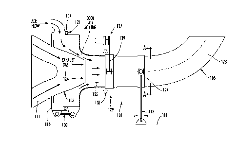
Figure 3 is a cross-sectional view (taken at cutting plane A-A of Figure 2) of
the engine exhaust system of Figure 2.
Figure 4 is a schematic end view of a rotatable nozzle of the engine exhaust
system of Figure 2 shown in a first position and in phantom in a second
position.
Figure 5 is a schematic detail view of a joint of the engine exhaust system of
Figure 2.
Figure 5 is a simplified end view of an actuator assembly of the engine
exhaust system of Figure 2.
Figure 6 is a simplified schematic view of a limit switch system of the engine
exhaust system of Figure 2.
Description of the Preferred Embodiment
To resolve the issue of aircraft exhaust ducts undesirably becoming non-
concentric due to relative movement between the engine and the airframe of an
aircraft and the issue of hot aircraft exhaust flow unduly impacting aircraft
components, an exhaust system provides (1) a means for linking the two ducts
together so that even with engine movement relative to the airframe, the two
ducts
remain concentric, and (2) a means for rotating an exhaust duct/nozzle to
direct
exhaust flow in an optimal direction. Therefore, if engine movement occurs for
any
reason, the airframe mounted secondary duct is pushed or pulled into
consistent
alignment with the primary duct for maintaining maximum ejector performance
while
also providing for selective control of the exhaust gas vector. Rotation of
the gas
vector allows for redirecting of hot exhaust gas from impinging on composite
parts
(such as rotor blades) or other heat-sensitive components during near-idle
conditions
when the aircraft id on the ground. In addition, the exhaust vector may be
redirected

CA 02652685 2008-11-17
WO 2008/127260 PCT/US2007/013675
-3-
while the aircraft is on the ground or in flight to alter the infra-red (heat)
signature of
the aircraft for avoiding heat-seeking devices, such as missiles.
Referring now to Figures 2 and 3, an embodiment of an engine exhaust
system 101 is illustrated. Exhaust system 101 comprises a tubular primary
exhaust
duct 103, a tubular secondary exhaust duct 105, and a slip joint 107 for
allowing
relative axial movement between ducts 103, 105. Primary exhaust duct 103 and
secondary exhaust duct 105 are also held in alignment by a drag link 109.
Secondary exhaust duct 105 is connected to an airframe 111 and is supported by
vertical struts 113 and a lateral strut 115, which are preferably struts
connected at
each end with uni-ball connectors. Vertical struts 113 carry vertical loads,
and lateral
strut 115 carries side loads. Preferably, the strut attachments are located on
or very
close to the center of gravity to avoid any undesired moments.
Primary exhaust duct 103 is attached directly to engine 117 for allowing
exhaust gas to flow from engine 117 through primary exhaust duct 103 and into
secondary duct 105. A forward end of secondary exhaust duct 105 is slipped
concentrically into and sealably joined to an engine flange 119 through the
use of o-
ring type seal 121 in slip joint 107, and use of o-ring seal 121 allows for
thermal
expansion of ducts 103, 105. 0-ring seal 107 is preferably a high-temperature
o-ring
type seal. Slip joint 107 also supports duct 105 in both vertical and
horizontal
directions, but not in an axial direction. Axial control of duct 105 is
accomplished
with drag link 109, which connects flange 119 to secondary duct 105. The
mounts of
drag link 109 are preferably uni-ball connectors, and this configuration
allows for
relative axial movement between engine 117 and secondary duct 105, but this
does
not allow for vertical or lateral movement. The single degree of freedom
associated
with drag link 109 allows engine movement to push or pull secondary exhaust
duct
105 consistently with primary duct 103 and keeps the system in the desired
alignment.
Secondary exhaust duct 105 has a curved portion 123 for altering the
direction of exhaust flow from its original flow path along central axis 124
of a fixed
portion 125 of duct 105 to a direction off the central axis of fixed portion
125. In the
nominal orientation, cured portion directs flow in the direction shown
relative to fixed

CA 02652685 2008-11-17
WO 2008/127260 PCT/US2007/013675
-4-
portion 125. However, curved portion 123 is rotatable generally about axis 124
through a range of motion of about 90 degrees to either side (or to the extent
of the
range of motion available in the particular application). Figure 4 shows an
end view
of secondary duct 105 with curved portion 123 in the nominal position (solid
lines)
and rotated to one side (broken lines). To enable rotation while retaining the
function
of the means for keeping ducts 103 and 105 concentric, a bearing band 127 is
disposed between curved portion 123 and struts 113, 115.
A joint 129, which is shown in Figure 5, joins curved portion 123 and fixed
portion 125 together. Joint 129 is configured to retain curved portion 123
axially by a
retainer 131 while allowing curved portion 123 to rotate relative to fixed
portion 125
along central axis 124. Also, a self-lubricated bearing coating 133,
preferably
Rexlon, is disposed at the interface of curved portion 123 and fixed portion
125.
Figure 6 is an end view of an actuator system 135, comprising an electric
motor type actuator 137 connected to curved portion 123 through the use of
wire
rope 139 and chain 141. Actuator 137 is selectively controlled to rotate
curved
portion 123 into a position yielding optimal exhaust gas flow direction,
thereby
controlling or eliminating aircraft component overheating or altering the IR
signature
of the aircraft. Actuator 137 may be controlled manually, but is preferably
controlled
using a micro-processor-based flight control computer.
Figure 7 shows an adjustable stop 143 operably associated with wire
rope/cable 139 and/or chain 141 for interacting with limit switch system 145.
Of
course, any other means for limiting, controlling, or causing rotation of
curved portion
may be used in alternative embodiments of the present invention.
The exhaust system provides for several advantages, including: (1) the ability
to maintain primary and secondary exhaust ducts in a desired orientation; (2)
selectively control the exhaust gas vector; (3) low weight; (4) increased
reliability and
durability; and (5) easy installation.
This description includes reference to illustrative embodiments, but it is not
intended to be construed in a limiting sense. Various modifications and

CA 02652685 2008-11-17
WO 2008/127260 PCT/US2007/013675
-5-
combinations of the illustrative embodiments, as well as other embodiments,
will be
apparent to persons skilled in the art upon reference to the description.

Representative Drawing
A single figure which represents the drawing illustrating the invention.
Administrative Status

2024-08-01:As part of the Next Generation Patents (NGP) transition, the Canadian Patents Database (CPD) now contains a more detailed Event History, which replicates the Event Log of our new back-office solution.

Please note that "Inactive:" events refers to events no longer in use in our new back-office solution.

For a clearer understanding of the status of the application/patent presented on this page, the site Disclaimer , as well as the definitions for Patent , Event History , Maintenance Fee  and Payment History  should be consulted.

Event History

Description Date
Inactive: COVID 19 - Deadline extended 2020-05-28
Common Representative Appointed 2019-10-30
Grant by Issuance 2012-12-18
Inactive: Cover page published 2012-12-17
Inactive: Final fee received 2012-10-03
Pre-grant 2012-10-03
Notice of Allowance is Issued 2012-05-03
Letter Sent 2012-05-03
Notice of Allowance is Issued 2012-05-03
Inactive: Approved for allowance (AFA) 2012-05-01
Amendment Received - Voluntary Amendment 2012-01-11
Inactive: S.30(2) Rules - Examiner requisition 2011-09-13
Inactive: IPC deactivated 2011-07-29
Inactive: IPC from MCD 2010-02-01
Inactive: IPC expired 2010-01-01
Letter Sent 2009-06-01
Letter Sent 2009-05-04
Inactive: Office letter 2009-05-04
Request for Examination Requirements Determined Compliant 2009-04-21
All Requirements for Examination Determined Compliant 2009-04-21
Request for Examination Received 2009-04-21
Inactive: Single transfer 2009-03-20
Inactive: First IPC assigned 2009-03-12
Inactive: IPC assigned 2009-03-12
Inactive: First IPC assigned 2009-03-12
Inactive: IPC assigned 2009-03-12
Inactive: Cover page published 2009-03-11
Inactive: Notice - National entry - No RFE 2009-03-06
Inactive: First IPC assigned 2009-03-04
Application Received - PCT 2009-03-03
National Entry Requirements Determined Compliant 2008-11-17
Application Published (Open to Public Inspection) 2008-10-23

Abandonment History

There is no abandonment history.

Maintenance Fee

The last payment was received on 2012-05-17

Note : If the full payment has not been received on or before the date indicated, a further fee may be required which may be one of the following

  • the reinstatement fee;
  • the late payment fee; or
  • additional fee to reverse deemed expiry.

Please refer to the CIPO Patent Fees web page to see all current fee amounts.

Owners on Record

Note: Records showing the ownership history in alphabetical order.

Current Owners on Record
BELL HELICOPTER TEXTRON INC.
Past Owners on Record
CHARLES HOLLIMON
JOHN BARBER
JOHN SHERRER
ROBERT LARAMEE
Past Owners that do not appear in the "Owners on Record" listing will appear in other documentation within the application.
Documents

To view selected files, please enter reCAPTCHA code :


To view images, click a link in the Document Description column. To download the documents, select one or more checkboxes in the first column and then click the "Download Selected in PDF format (Zip Archive)" or the "Download Selected as Single PDF" button.

List of published and non-published patent-specific documents on the CPD .

If you have any difficulty accessing content, you can call the Client Service Centre at 1-866-997-1936 or send them an e-mail at CIPO Client Service Centre.


Document
Description 
Date
(yyyy-mm-dd) 
Number of pages   Size of Image (KB) 
Representative drawing 2012-11-28 1 9
Claims 2008-11-17 6 160
Abstract 2008-11-17 1 65
Drawings 2008-11-17 4 41
Description 2008-11-17 5 208
Representative drawing 2008-11-17 1 13
Cover Page 2009-03-11 1 41
Claims 2012-01-11 6 153
Cover Page 2012-11-28 1 41
Maintenance fee payment 2024-06-07 42 1,734
Notice of National Entry 2009-03-06 1 193
Courtesy - Certificate of registration (related document(s)) 2009-05-04 1 102
Acknowledgement of Request for Examination 2009-06-01 1 175
Commissioner's Notice - Application Found Allowable 2012-05-03 1 163
PCT 2008-11-17 14 335
Correspondence 2009-05-04 1 15
Correspondence 2012-10-03 3 79